Whether you need to bill your clients the time your work on a drawing or just want to know how efficient you are (maybe your boss wants to know), you can do it in AutoCAD. You do this with the TIME command, which automatically tracks the time you work on a drawing.
To use the TIME command, enter time on the command line.
You see the following listing:
Current time: Obviously, this shows the current time, but also includes the date
Created: The date and time the drawing was created
Last updated: The time when the drawing was last saved
Total editing time: The accumulated time spent in the drawing from session to session. AutoCAD does not include plotting time or time that you worked but quit without saving your changes
Elapsed timer: Also accumulated time spent in the drawing, but you can turn this on and off as well as reset it
Next automatic save in: Shows when your drawing will be automatically saved. Use the OPTIONS command and display the Open and Save tab to set how often you want to automatically save your drawing
Next is the Enter option [Display/ON/OFF/Reset]: prompt. Here’s what those options do:
Display: Updates the listing with current times
ON and OFF: Turns the elapsed time on and off
Reset: Resets the elapsed time to zero
Using these options, you can keep track of the time you spend on a drawing.
Comment from a reader that we find useful to share here. – TIME, of course, tracks elapsed time not actual working time. So, if you leave the timer on while at lunch TIME reports incorrectly (unless you are discussing work over lunch). TIME must be turned OFF and ON when not working on files.
Another option
The Express Tools EDITTIME command (type it on the command line) tracks active editing time. It can represent your actual work more accurately than the TIME command, but you need to start it to start tracking. You can reset the time and use the timeout option to suspend counting after a certain period of inactivity.
Do you track your drawing time? Share your tips and techniques by leaving a comment!
Last time we did the poll was in 2014. It’ll be interesting to see what has or has not changed since then.
Many AutoCAD users have a favorite mouse, sometimes with lots of buttons on them. You may have a keyboard that makes entering data easier. Perhaps you think you have the best (and biggest) monitor around.
You probably also use 3rd-party software. Let’s share our hardware and software secrets! Leave a comment!
If the item is available on Amazon.com, please give the Amazon.com URL. Otherwise, give as much information as you can and where to purchase it.
Peripherals
Which mouse do you use? Do you use a puck or stylus? Do you have a special keyboard? Can you recommend a monitor? How do you set up your monitor, is it just single monitor or 2 even 3 monitors? Do you use any mobile devices like tablets to assist with sketching/drafting?
Why did you make those choices? Why are they great for AutoCAD users?
Software
Have you purchased 3rd-party software that works with AutoCAD? What does it do? Where can others buy it?
Leave a comment and share you good — and maybe bad — experiences!
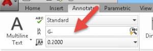
Suppose that you want to rename some text labels. For example, you have some part numbers that start with G- and now you want them to start with J- or you want to change every instance of “box” to “rectangle”.
First, it may be hard to find all of the instances of the text you want to change and if there are a lot of changes, it would be very time consuming to change each one individually. Instead, you can use the FIND command, which lets you find and replace text anywhere in your drawing. It finds the following types of text:
Single-line text
Multiline text
Text in tables
Block attributes
Dimensions
Hyperlinks and hyperlink descriptions
Choose Annotate tab, Text panel, Find Text, and enter the text you want to find in the Ribbon’s text box. Then click the Find Text button or just press Enter.
The Find and Replace dialog box opens with the text you entered in both the Find and Replace text boxes.
Transparency gives you the opportunity to create presentation-ready drawings. You can draw an object that is up to 90% transparent. Here you see some trees filled with a 60%-transparent solid fill.
As with other object properties, you should use the Layer Properties Manager to create a layer and specify the transparency as a layer property. Here you see a red layer that is 75% transparent.
Transparency is pretty useless for the line that delineates an object, but is quite useful for a solid fill hatch or a gradient. Here you see the effect of a red 75%-transparent layer on top of an opaque blue layer. The result is purple at the point of overlap.** As one of our readers point out – To show Transparency effect on your drawings, remember to check if the correct display mode is activated. Here is how – Enter “TRANSPARENCYDISPLAY” in the command prompt, then enter “1” to activate.
To create an object with a partially transparent solid fill, follow these steps:
Open the Layer Properties Manager (the LAYER command).
Click the New Layer button and name the layer.
In the Color column for that layer, click the color swatch and choose a color.
Click in the Transparency column for that layer to open the Layer Transparency dialog box and type a value between 0 (completely opaque, the default) and 90 (mostly transparent). Then click OK.
Make any other changes that you want to the layer’s specifications and close or collapse the Layer Properties Manager.
From the Home tab> Layers panel< Layer drop-down list, choose the new layer to make it current. (You can also do this after the next step.)
Draw a closed object.
Choose Home tab> Draw panel> Hatch.
In the Pattern panel, choose Solid.
At the Pick internal point or [Select objects/settings]: prompt, pick inside your closed object.
Press Enter to accept the solid fill and end the command.
Another useful comment from our reader is in relation to xref. The transparency functionality only works if it is set in the current drawings, not as Xref to another drawing. The work around is to copy with base point with all the data from the external file & paste it into the drawing.
Also, if you have trouble seeing the transparency setting after plotting to PDF, please make sure that you have checked “Plot Transparency” under Plot options.
Do you use transparency in your drawings? Why or why not?
The command line is an essential component of drawing in AutoCAD. Even if you don’t type commands there, you need to look at it for prompts and you probably use it to specify options.
The command line is actually a palette window. By default, the command line is docked at the bottom of your screen.
See more of the command line
Another default is that the command line palette shows 3 lines of text: the Command: prompt and 2 previous lines. You can drag the upper edge of the palette to show more lines.
To display the entire history of the command line, press F2 to open the AutoCAD Text Window.
See less of the command line
On the other hand, if you think that the command line takes up too much space you can hide it or collapse it.
To hide the command line, pres CTrl + 9. So you don’t do this by accident without knowing how to get the command line back, you see this message:
Check the Always Close the Command Line Window check box to avoid seeing this message the next time. Then click Yes. Now, you can easily toggle the command line to display and hide it.
To collapse the command line (like other palettes such as the Properties window or the Tool Palettes), first undock it by dragging its gray title bar at the left.
Then right-click the gray title bar and choose Auto-Hide. The command line palette collapses to a small gray bar. That’s pretty small! But as soon as you hover your cursor over the bar, the command line expands.
Let AutoCAD help you
Starting with AutoCAD 2012, when you start to type a command, AutoCAD auto-completes. If you pause, you see all commands starting with the letters you typed and you can choose the desired command.
You can do minor editing as you type, in case you make a mistake (before pressing Enter):
Home: Moves the cursor to the beginning of the line
End: Moves the cursor to the end of the line
Left arrow: Moves the cursor to the left
Right arrow: Moves the cursor to the right
Backspace: Deletes the character to the left of the cursor
Delete: Deletes the character to the right of the cursor
You can also use Ctrl+V to paste text from the Windows clipboard.
Retrieve command line
One of our readers suggests these 5 easy steps to retrieve command line:
Go to bottom blue area below drawing area and right click.
Choose Hide Task Bar.
Move hidden command bar to drawing area.
Turn back on task bars.
Reposition Command baring
More command line tricks & tips
Here are some more ways to make using the command line easier:
Repeat the last line you entered: Press the Up arrow and pres Enter.
Copy a previous command from the Text Window: Press F2 to open the Text Window, highlight the item you want, right-click, and choose Paste To CmdLine.
Repeat a recent command: In the Text Windows, right-click and choose Recent Commands. Then choose the command you want.
This one is from our reader comments: Copy the command line history texts, Type “COPYHIST” in the command line window. Once you hit the enter button, texts are automatically copied in your clipboard. These are just text lines, you can paste it anywhere.
Do you have any other tips for using the command line window? Leave a comment!
In previous posts, I explained how to insert blocks from the Tool Palettes window, the DesignCenter, and the Content Explorer. In this tip, I’ll explain how to create block library and use the INSERT command to insert blocks that are in that library.
You don’t need a special tool like the Tool Palette window, DesignCenter, or Content Explorer to insert a block. Instead, you can save all of your blocks as separate drawings in a folder and insert them from that folder.
I explain how to create a drawing from a block in my tip, “Write blocks to save them as separate files.” This tip explains the WBLOCK command, which automatically uses the base point of the block as the base point of the drawing, so that you can easily insert the block in the right place.
Once you have saved your blocks as drawings in a block library folder, you can easily use the INSERT command to find and insert them. Follow these steps:
On the Home tab, in the Block panel, click Insert.
In the Insert dialog box, click the Browse button to browse to your library folder and then the block you want inside that folder. Remember that each block is a separate drawing.
Double-click the block you want to insert.
Choose the settings you want in the Insertion Point, Scale, and Rotation sections of the dialog box.
Click OK.
If you kept the default option to specify the insertion point on-screen, pick the point you want. Specify scale and/or rotation if you also set them to be specified on-screen.
** One useful tip from our reader’s comment is to create one file with all your most commonly use blocks, then insert it in your drawings. Each block is now available in the insert block drop down list.
How do you manage your blocks? Do you have a formal block library? How do you set it up and access its blocks? Leave a comment!
Creating a block is a basic task that every AutoCAD user should know. But even if you’ve been using blocks for years, I think that you’ll find the links at the end to more advanced tips helpful. Put together, these tips make up an advanced tutorial on blocks.
What is an AutoCAD block?
A block is simply a collection of objects (it could be one object) that has a name. Blocks have several advantages:
You can insert them again and again, saving time. In fact, you can insert them into other drawings as well.
A block uses less electronic space than individual objects, so your drawing file is smaller.
By updating a block’s definition, you can update all the blocks in the drawing.
Note: Dynamic blocks are blocks that have added parameters that function in certain defined ways. Sign up below to get your Free tutorial on creating a complete dynamic block, including a drawing to practice on. You’ll make a movable chair, resizable desk, and more.
How do you create a block?
To create a block, follow these steps:
Draw the objects that you want in the block.
Choose Home tab> Block panel> Create to start the BLOCK command. The Block Definition dialog box opens.
Type a name in the Name text box. The name can have spaces.
You need to specify a base point. That’s the point at which you’ll insert the block. In the Base Point section, click Pick Point. Be sure to use an object snap for accuracy! You’ll immediately be returned to the dialog box.
In the Objects section, click the Select Objects button. Select the objects and press Enter to return to the dialog box. Tip: You can select the objects before using the command and they’ll show up in the dialog box.
Just below, choose Retain, Convert to Block, or Delete. These options control what happens after you create the block.
In the Behavior section, you can make a block Annotative (more info here), force it to scale uniformly and choose whether to allow exploding.
In the Settings area, choose the block unit. You can choose Unitless but if you choose a unit, AutoCAD will try to scale the block appropriately when you insert it into another drawing. You can also add a hyperlink if you want.
Finally, you can add a description in the Description box. A description is helpful in the DesignCenter, when you want to insert the block from another drawing.
Click OK to complete the box. If you chose Delete, the objects disappear. You can use the OOPS command to bring them back.
Next time, I’ll cover the process of inserting a block.
Other Useful Related tips on AutoCAD blocks to check out:
AutoCad block naming conventions can help you quickly identify block types, especially in drawings with many blocks or within the block libraries.
There is no one way fits all approach, however, from our experience, three major criteria for a good naming standard are:
Descriptive/Meaningful
Concise
Consistent
So what is a Descriptive/meaningful, intuitive, simple and consistent naming standard actually means?
The name should be a description of the actual block, which tells about the block without seeing it. The name should also be meaningful and obvious to your company’s current user and therefore more intuitive to any future users.
Although there maybe no limit on characters in block names, it is also important to keep it simple and concise.
Last but certainly not least important is that whichever block naming system you decides to go with, it is critical to be consistent.
If your new block naming convention follows the above criteria, it will avoid unnecessary confusion and/or time wasting and it will be easier for new people to learn and get on board with the system.
Below is an example of a descriptive naming structure for door or window blocks for an architectural plan.
Company_Type/Operation of Door/window & No of Panels_ Width_Height
So for a 4 panel sliding door, 4000mm wide 2400 high, you can name it as descriptively as possible such as AACAD_SLIDEDR4P_40W24H
Note: The company initial is only useful if you are sharing & working on the same files with other company.
So if you prefer a simpler and more concise option, you can simply name this block as SD4P_40.24
If you go with this simplified naming convention, it may be useful to also have a print out or an attachment file with legends that clearly shows how the generic abbreviation works.
Comment and share with us below, the block naming convention/system/structure that you use and find most useful.
You can break a line or other object into two objects without any space between them using the BREAK command in AutoCad.
Here are 5 easy steps to achieve it:
Type in BREAK at the command line or select break tool
Select the object you wish to break
Select First Point Option (F) then
Pick the point where you wish divide the object
When prompted to specify second break point, type @ and Enter
Note: You probably know that @ means last point picked, so AutoCAD breaks the object at the first point you picked and it becomes two objects. You can’t see the different until you try to select one of them.
How about if you want to break the line with a specified distance/gap in between? (For this example, we want 100 unit line, 500 unit gap to the second line). We can easily do this by using the “from” command inside of the Break command.
Follow these simple steps below:
Type in BREAK at the command line or select break tool
Select the object you wish to break
Select First Point Option (F) then Enter.
From and Enter. Then for offset prompt, Type @100,0 and Enter
When prompted to specify second break point, type @500,0 and Enter
You now have a gap of 500 unit in between the now separate two lines
Note: if you have reference points to pinpoint exact position of the gap, you can also use the mouse & drag to align to the reference lines instead of typing in the exact unit.
Eric Fransen emailed in a nice macro for this that you can put on a toolbar button:
^C^CBREAK;\F;\@;
Alan Praysman sent me a nice AutoLISP routine that he wrote that uses a single click to specify the object and the break point. Because it allows object snaps, you can pick the right point easily. Download the file (zipped).
The Quick Select dialog box is a simple filtering device that helps you select the objects you want. For more advanced filters and for when you want to save filters, use the FILTER command.
There are 4 ways to open Quick Select in AutoCAD:qs
Home tab> Utilities panel>Quick Select
With no command active, right-click in the drawing area and choose Quick Select
Click the Quick Select button in the Properties palette
Type qselect on the command line.
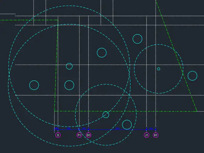
There are many ways to simplify your selection with Quick Select function. Using the sample drawing below, I will demonstrate how to use this function to easily select a certain type of object with particular perimeter, in this case, to select all the circles with radius of 750
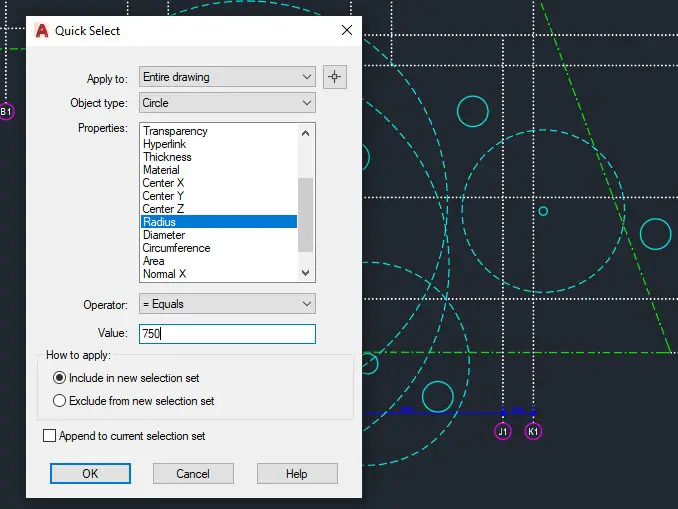
So open the Quick Select tool using one of the 4 methods described above then follow this steps
Under object type, select circle
For properties, select Radius. Note: you can see here all the perimeters that you can use to define your selection.
Under value, key in 750 then click OK
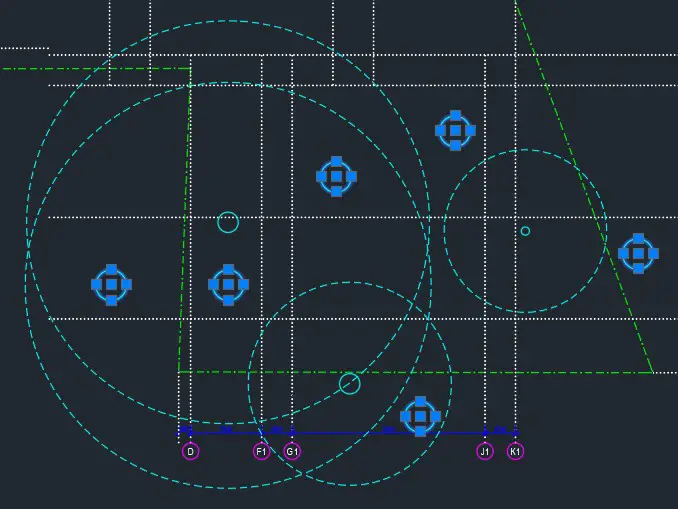
And there you go, with these simple steps, you now have successfully selected all the cicle with radius of 750 in this drawing.
Tom has posted a question below that I feel may help our readers:
Q: Hi Ellen, I’m trying to erase a bunch of tiny circles and don’t want to pick them 1 by 1. I thought of selection sets, but I’m not too familiar with using them. Right then, I got your email newsletter, hence, this post. I get how to create a selection set with qselect, but how do I do something with the selection set? Do I need to name and recall it? Thanks for your help.
A: You can use the P (Previous) option in the next command’s Select object: prompt. This picks up the previous selection set. Or, if the objects are still selected, just start the ERASE command to apply it to the selected objects.
How do you use the Quick Select feature? Or do you have other methods of creating filters for selecting objects? Leave a comment!
Important: While we don't collect cookies, some of our 3rd-party services (such as PayPal and WordPress) do, to give you a safer and better browsing experience. Read about how we use cookies and keep your personal information secure by reading our Privacy Policy here.