Sometimes you need to create a 2D profile that is a combination of the basic geometrical shapes that AutoCAD creates. While you might be able to use the PLINE command to create what you want, in some cases, 2 other methods may be easier.
Subtract shapes with the SUBTRACT command
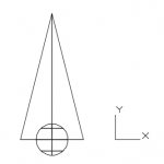
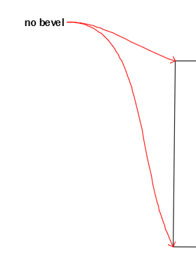
For example, let’s say that you want to create this profile.
Depending on the information you have about the radius of the circle and length of its inset, it might be easier for you to start with these objects:
Simple linetypes allow you to apply a repeating series of dashes, dots, and spaces to your objects. Complex linetypes can also include text or shapes.
Recently, a reader said that his linetype was defined as dash-dot but displayed as a continuous linetype. If you have this situation, zoom in and see if you can see the dots and dashes.
If you find that the linetype patterns in your drawing are too long or short, the line might look continuous. How often the pattern is repeated is affected by three factors:
The linetype definition itself
The global linetype scale
The object linetype scale
1. Use a different linetype definition
One choice is to change the linetype. A number of linetypes come in short, medium, and long variations, such as Dashedx2, Dashed, and Dashed2, as you see here.
Note: If you use ISO linetypes, the pattern definitions are much longer than the other linetype definitions, so you may need to make adjustments to the linetype scale.
2. Change the global linetype scale
Another choice is to change the global linetype scale, which affects all noncontinuous linetypes in your drawing. AutoCAD multiplies the linetype definition by the global linetype scale to calculate the length of each repetition of the linetype:
Linetype scales larger than 1 result in longer sections — and fewer repetitions of the linetype definition
Linetype scales less than 1 result in shorter sections — and more repetitions of the linetype definition
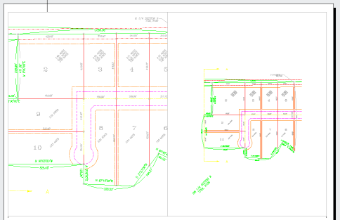
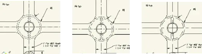
Here you see 3 versions of a drawing with linetypes at linetype scales of 0.5, 1, and 2. As you can see, a scale of 2 is too large and a scale of 0.5 is too small. A scale of 1 is just right.
When you draw, you just want to be able to distinguish the linetype both when you can see the entire drawing on the screen and when you zoom in close. The main reason to scale linetypes is for plotting. A linetype scale that works for a drawing of a house while you’re drawing may look continuous when you plot it at a scale factor of 1 = 192.
When plotting, first try the plotting scale factor for the linetype scale. If that doesn’t give you the results you want, try 1/4 or 1/2 of the scale factor — in the 1 = 192 example, you could try a linetype scale of 96 or 48.
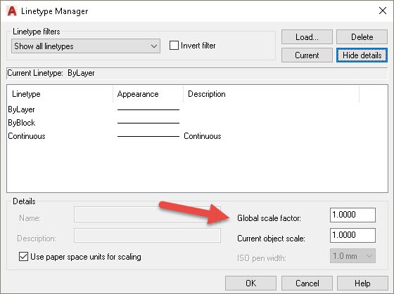
To change the linetype scale, click the Linetype drop-down list in the Properties panel of the Home tab and choose Other to open the Linetype Manager. Click Show Details if the lower portion of the dialog box isn’t displayed.
In the Global Scale Factor text box, type the scale factor that you want. Click OK. The drawing regenerates, changing the scale of every noncontinuous linetype in the drawing.
Tip: The global linetype scale is stored in the LTSCALE system variable. You can change the linetype scale by typing ltscale on the command line and typing a scale.
3. Change the object linetype scale
Sometimes you may want the linetype spacing to be different for just 1 or 2 objects. Maybe an object is too small to show the linetype clearly.
To change the linetype scale, open the Linetype Manager. Click Show Details if necessary and in the Current Object Scale text box, type the scale factor you want. Click OK. Now all objects that you draw use the current object linetype scale. When you’re done drawing objects at that linetype scale, remember to change the linetype scale back to 1.
Tip: The current object linetype scale is held in the CELTSCALE system variable. You can also change the current object linetype scale by typing celtscale on the command line and typing a scale.
If you have also set the global linetype scale to a value other than 1, AutoCAD multiplies the 2 linetype scales. So if you have a global linetype scale of 12 and a current object linetype scale of 0.5, objects you draw will have a linetype scale of 6.
To change an existing object’s linetype scale, select the object and open the Properties palette. Click Linetype Scale and then type the new linetype scale. This linetype scale affects only the selected object. It does not affect the global linetype scale.
Have linetype scales frustrated you? Do you have any tips you can share? Leave a comment! And please use the Share buttons to share this with your colleagues.
But due to various reasons, you may decide to change their names. Maybe you made a mistake or you’re working on a drawing created by someone else and you want to change the names to remain consistent with your standards.
You can achieve this easily with the RENAME command. Here are the steps:
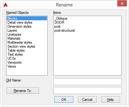
The command isn’t on the ribbon, so just type rename on the command line to open the RENAME dialog box.
Click the type of named object that you want to rename from the list on the left.
Select the object you want to rename on the right. It appears in the Old Name text box.
Type the new name in the Rename To text box
Click OK.
It’s really easy, right? But I think that many people don’t even know that the RENAME command exists–maybe because it isn’t on the ribbon.
Do you use the RENAME command? What type of situation has it helped you resolve?
This is a guest blog post by Parvez Mahmood, General Manager, Engineering Systems/ER Solutions in Islamabad, Pakistan. He has been teaching AutoCAD for last 10 years to industrial and university students.
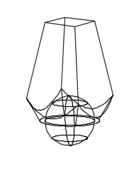
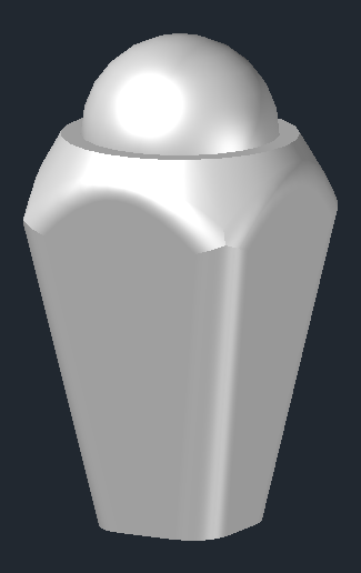
It’s a tutorial that will show you how to draw a fancy square glass bottle cap in AutoCAD. It’s a great AutoCad tutorial to work through if you want to advance your 3D skills.
On the right, you can see what the final bottle cap will look like, with perhaps slight differences in proportion, depending on the values you use.
Set up your environment
Select Workspace 3D Basic/3D Modelling
Ortho ON.
UCS WORLD. (To align the object with the grid).
View PLAN in world UCS
Visual style 2D WIREFRAME
Start drawing
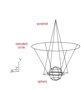
Command Pyramid. Let default/select CIRCUMSCRIBED. Enter Start Point as 10,10. Enter base Radius 5 and height 20.
Zoom IN/OUT and PAN to see the pyramid in the centre of the drawing area. See the figure on the right.
Command Sphere. OSNAP ON. Move the cursor over the centre of the diagonal lines of the pyramid. It will be highlighted with cursor read out as 3D Center or just Center. Acquire the point by clicking and enter R2.5. (See figure below). The sphere will be formed at the centre of the base of the pyramid.
Author’s Note: If the VisStyle is not 2D Wirerame, cursor will acquire tip of the pyramid as 3D Vertex. The sphere will now be formed at the top tip of the pyramid. You will now have to move the sphere, selecting its centre as base point, by 0, 0, -20.
Ellen’s Note: I just see Endpoint or Center (not 3D Center or 3D Vertex) and it’s on top, so I have to move it down. Here you see the result in Left view.
Change view to bottom.
Set UCS WORLD. (If you don’t, the extrusion of step 7 will be away from the pyramid causing the operation of step 8 to delete both the pyramid and the truncated cone.
Command Circle. Move the cursor over the centre of the crossing diagonal lines of the pyramid. 3D Centre point will be highlighted as in step 3. Acquire the point by clicking. Enter Radius 3. (Ellen’s note: I just see Center, not 3D Centre/3D Center.)
Extrude circle with a Taper of -30 and and extrusion of 10 to create a cylinder . A truncated cone will be created overlapping and surrounding the pyramid. Here you see the result shown from the Left view.
Perform Intersection of pyramid and cone. (Ellen’s note: Cool!)
3D Orbit the view a bit to see the inverted cap with all vertical and bottom edges clearly. (After the 3DORBIT command, click somewhere in the centre and move the cursor south and then slightly to either left or right to get the view as in the figure below. Enter to come out of Rotate command.
Fillet any two adjacent vertical sides and then the other two with radius 2. (Ellen’s Note: Radius 1 worked for me. Also, I chose Selection panel, Filter, Edge.)
Fillet any two adjacent bottom edges and then the other two with radius 2. (Try R 1 also). Note that these edges are now small segments This may be easier to do in Realistic view style.
Union the parts.
Make final visual adjustments
Change the Visual Style to realistic.
Command Rotate3D. Select the cap. Enter. Choose X axis. Then asks for a point on the X axis. Then rotation. I accepted 0,0,0 and set rotation to 180.
Select View TOP. The cap appears upright in the top view.
Here’s the final view again. (Ellen’s note: I think it’s beautiful!)
You should draw full size, but rarely do you plot at full size. That’s because your models are not usually the same size as your sheet of paper. Therefore, you have to scale your drawing when you plot. There are a number of ways to do this, but here is the most direct method I can think of.
Click a layout tab. Usually, you’ll see 1 default layout. You can delete or resize it. You can create new layouts on the Layout tab, in the Layout Viewports panel.
Select a viewport. To do this, you must be in paperspace. If you can’t select the viewport, double-click outside it. The viewport border is heavy when you are in model space on a layout and returns to its normal width when you are in paperspace.
Open the Properties palette on the View tab, in the Palettes group, or use the keyboard shortcut, which is Ctrl+1.
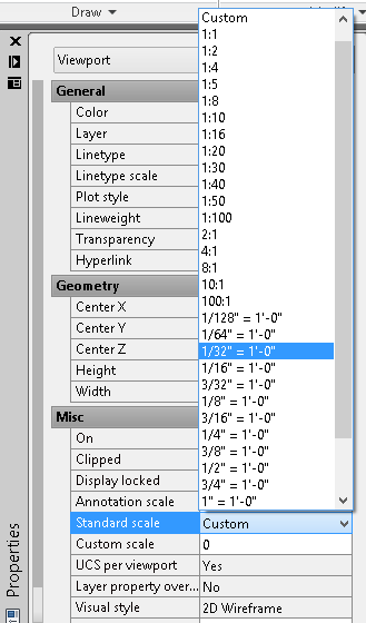
Under the Misc heading, click the Standard Scale item; then click the down arrow to expand the list of scales. If you aren’t sure which scale you want, pass your cursor over some of the scales to see the result in the viewport. Choose the scale that fits your objects the way you want. Most people are required to use standard scales, but you can use the Custom item and make up your own if you want.
Once you have set the scale, you should lock the viewport. you can do this in the Properties palette, changing the Display Locked item’s value to No. A quick way is to click the Lock/Unlock button on the status bar, next to the VP Scale pop-up list.
With the newer AutoCad version, you can also do the following steps:
on Layout tab, go to View/Viewports/1 Viewport
specify the corners of the new viewport to the desire size
double click into the new viewport region. The viewport border will be highlighted thicker to show the viewport is active.
with the cursor still within the viewport, type zoom, then select S for Scale,
Type in the desire scale of drawing to be plotted on the paperspace i.e 1:100xp (to represent drawing in 1:100 scale)
Move the cursor out of of viewport, then double click to exit the viewport.
Click on the border of the viewport, then right click and select Display Locked/Yes to lock the scaled viewport
the viewport’s border can now be resized to display the desire extend of the drawing by dragging the grip points.
Viewport can also be moved around the paperspace to the desire position.
How do you create a scale for your viewports? Leave a comment!
There’s no reason to recreate the wheel – or text or dimension styles, if you have them elsewhere. The easiest way to import a text or dimension style from another drawing is to use the DesignCenter.
Follow these steps:
Go to the View tab then locate DesignCenter icon under the Palettes section or simply type “ADCENTER”. A reader also make a useful comment of another shortcut. Type Ctrl+2 to bring up or close down Center window.
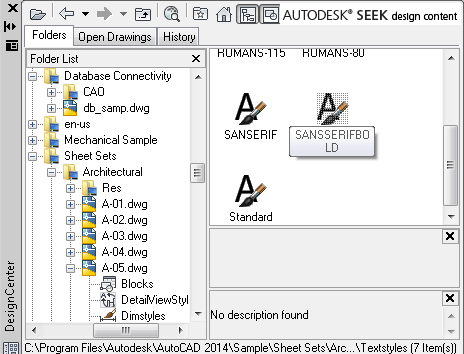
From the Folder list (it looks a lot like Windows Explorer) navigate to the folder where the drawing that has the text or dimension style that you need is located.
Click the drawing’s Plus sign to expand it and choose the type of elements that you want to import, such as a text style.
On the right, you’ll see a list of the text styles that are available in the drawing. Drag the one you want onto the drawing area.
You can also use the Content Explorer, although the set-up process is more complex. Here are the steps:
Click the Plug-Ins tab, then click Explore.
If the folder where the drawing you is not listed, click Add Watched Folder at the bottom.
Navigate to the folder, select it, and click OK. AutoCAD scans the drawings in the folder; this process may take some time. The Content Explorer works best when you plan in advance.
When the process of scanning is done, or if the folder you want is listed, you can do one of two things:
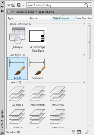
If you know the name of the element, enter it in the Search box at the top of the Content Explorer.
If you know the location and name of the drawing, double-click the folder and navigate to the drawing. Double-click the drawing to display its elements.
When you see the element you want, such as a text style, drag it onto the drawing area to import it into your drawing.
Our reader, Doug, mentioned a 3rd simple method to easily import text and dimension styles from other drawings, which is to Copy/paste the text & dimension styles you want from one drawing to another. You can also ‘insert’ the drawing with the wanted data and just cancel out of the command once it asks you for an insertion point. This will bring in ALL data from the original drawing, ie. text, dim styles, blocks, etc.
Let us know which option you prefer: 1,2 or 3? Do you have any other tips for importing text or dimension styles? Leave a comment!
If you use leaders, you should consider creating a style. Once you save the style, you can use it whenever you need a leader.
Here are the steps to create a multileader style:
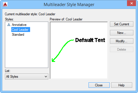
Go to Home tab, Annotation panel and click the down arrow to expand the panel. Click the Multileader Style icon to open the Multileader Style Manager dialog box.
Click the New button to open the small Create New Multileader Style dialog box. Type a new style name and choose an existing style to start with. You can choose to make the style annotative by clicking the Annotative checkbox. Click Continue. The Modify Multileader Style dialog box opens, showing the name of the style that you specified. This dialog box has 3 tabs.
Most mice have a wheel and you can use it in a number of ways — scroll it in 2 directions, click it, and double-click it. Plus, you can combine keys such as the Shift key with the mouse wheel to get even more capabilities. AutoCAD makes good use of your mouse wheel. Here are some of the options.
System variables that affect the mouse wheel
There are 3 system variables that affect how your mouse wheel works:
ZOOMFACTOR: This system variable sets the amount of magnification change that occurs when you scroll the wheel forward or backward. You can choose from 3 to 100 and the default value is 60. A higher value changes the magnification more.
ZOOMWHEEL: This sets the direction of the scrolling. By default, this is set to 0, which means that when you scroll the wheel forward you zoom in and when you scroll it backward, you zoom out. If you set the value to 1, you reverse the action. Most people change this setting when they have other software that works the opposite of the AutoCAD default and they want the zooming to be the same in all their software.
MBUTTONPAN: By default (set to 1), when you press the mouse wheel and drag, you pan across your drawing. However, when you set this system variable to 0, the wheel acts like a middle button and supports the action that you define in the CUI or CUIX menu file, which could be just about anything.
Mouse wheel actions that you can use
Common actions you can perform when MBUTTONPAN is set to the default of 1:
Zoom in or out: Rotate the wheel forward to zoom in, backward to zoom out. (As mentioned above, you can change the direction with the ZOOMWHEEL system variable.)
Pan (joystick): Press Ctrl and the wheel button and drag the mouse. This is used in 3D, although I’m not sure I understand exactly what’s happening. Try it out and see if it’s useful for you.
3D Orbit: Press Shift and the wheel button and drag the mouse.
Free Orbit: Press Ctrl, Shift and the wheel button all at once and drag the mouse. You’ll see the 3D orbit arc ball as you do this.
Do you have any mouse wheel tips? Leave a comment!
Several people have asked about inexplicably large files.
Kerry Overall wrote me,
I’ve seen unusually large CAD .dwg files. I had the same problem when a colleague stumbled onto a solution that greatly helped me. Open the drawing….wblock, click on “Entire Drawing” and save it. I had a simple file that was 73mb and by doing this it reduced it down to 3mb. And quickly , too.
The WBLOCK command writes (saves) the objects in a drawing as a new drawing. You can specify specific objects or the entire drawing.
A bonus is that you lose many settings in the current drawing. You can therefore use this technique to troubleshoot problem drawings that don’t behave the way you want them to. It’s often hard to ferret out the settings that might be causing the problem — such as system variables — so moving the objects to a new drawing can be an easy fix.
Here are the steps to reduce extremely large Autocad file with wblock command:
If you want, you can select objects in advance.
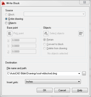
Type WBLOCK on the command line or choose Insert> Block Definition panel> click the Create Block drop-down arrow and choose Write Block. (It’s easiest to just type it on the command line.) The Write Block dialog box opens. If you pre-selected objects, the number of objects appears in the Objects section of the dialog box.
To write the entire drawing, choose Entire Drawing at the top.
You can choose a base point. If you want to be able to insert the drawing (or the selected objects) using a base point on one of the objects, for example, click the Pick Point button and specify the base point.
In the Objects section, you can choose to retain the objects in the current drawing, convert them to a block, or delete them from the drawing.
In the Destination section, click the Ellipsis button and browse to the location where you want to save the new drawing. Give the drawing a name and click the Save button.
If desired, choose units from the Insert Units drop-down list. You can choose Unitless. You can even choose light years or parsecs if you’re thinking really big!
Click OK.
If you did these steps to make your drawing smaller, go into Windows Explorer and check the size of the original and new drawings.
There are also many useful additional tips in the comment section. Go and check it out if this tip doesn’t work for you.
What other techniques have you used to reduce the size of AutoCAD drawings? Leave a comment and share with others!
Important: While we don't collect cookies, some of our 3rd-party services (such as PayPal and WordPress) do, to give you a safer and better browsing experience. Read about how we use cookies and keep your personal information secure by reading our Privacy Policy here.


 This is a guest blog post by Parvez Mahmood, General Manager, Engineering Systems/ER Solutions in Islamabad, Pakistan. He has been teaching AutoCAD for last 10 years to industrial and university students.