Entering the world of Computer-Aided Design (CAD) can be a daunting challenge, especially with the multitude of software options to master. As an aspiring CAD operator in 2024, you might be asking yourself, “Which CAD software should I learn first?” Moreover, budget constraints could further complicate this decision. Fret not, this guide will help you navigate through these choices.
AutoCAD: The Industry Standard
AutoCAD, from Autodesk, has been the industry standard for many years and is an excellent starting point for any CAD operator. Its intensive set of features allows for 2D drafting, 3D modeling, and documentation. Although not free, AutoCAD offers a free trial and discounted rates for students, making it accessible for beginners.
SolidWorks: The 3D Design Specialist
If you’re more inclined towards 3D modeling, SolidWorks is a sound choice. Although this software isn’t free, it is incredibly user-friendly, and its feature-based approach to 3D design makes it a favorite among mechanical engineers.
For those looking for a free software option, SketchUp is an excellent choice. It’s a powerful yet straightforward tool for creating, viewing, and modifying 3D ideas quickly and easily. SketchUp offers a free version, SketchUp Free, which operates entirely online, requiring no downloads. Its intuitive interface makes it an ideal starting point for beginners.
Fusion 360: The All-Rounder
Another noteworthy contender is Fusion 360, also from Autodesk. This software is a cloud-based 3D CAD, CAM, and CAE tool that combines industrial and mechanical design, simulation, collaboration, and machining in a single package. Fusion 360 offers free licenses for students, educators, and startups, making it a cost-effective choice.
Revit: The Architect’s Choice
For budding architects, Revit is the go-to software. It is not free, but its ability to incorporate Building Information Modeling (BIM) makes it invaluable in the architectural and construction industries.
FreeCAD: The Open-Source Option
FreeCAD is a fully fledged parametric 3D modeling software that is entirely open-source. It’s a great tool for those interested in engineering and product design, but are restricted by budget. Since it’s open-source, it has a strong community behind it, providing a wealth of resources and guides.
In Conclusion
The CAD software you choose to learn first is largely dependent on your career aspirations, the industry you’re looking to enter, and your budget. AutoCAD and SolidWorks are industry standards, Revit is essential for architects, while SketchUp, Fusion 360, and FreeCAD offer free or cost-effective options. Remember, mastering the software is just one aspect; understanding the underlying design principles will be key to your success as a CAD operator in 2024.
Using ChatGPT to create AutoLISP scripts for AutoCAD can be an effective way to streamline your design process. AutoLISP is a dialect of the programming language LISP (List Processing language) that’s used specifically for Autodesk’s AutoCAD software.
Here’s a general guide on how you could use ChatGPT to create AutoCAD Lisp:
1. Define Your Objective:
Clarify what you want the AutoLISP script to do. Maybe you want it to automate a certain repetitive task, or perhaps you need it to extract specific information from your AutoCAD drawings.
2. Consult ChatGPT:
Engage with the AI, explaining your objective as clearly as possible. For example, you might say, “I want to create an AutoLISP script that will count the number of blocks in an AutoCAD drawing.”
3. Extract the Information:
ChatGPT will then provide you with information based on its extensive knowledge. It could give you step-by-step instructions, relevant coding examples, or even potential code snippets.
Here’s an example of how this interaction might look:
You: I want to create a LISP script to count the number of blocks in an AutoCAD drawing.
ChatGPT: Sure. Here’s a basic example of how you might do that:
In this script, ssget is used with a filter to select all block insertions in the drawing. sslength then determines the length of the selection set, which is the number of blocks. Finally, alert displays this number in a dialog box.
Remember to load your LISP script into AutoCAD to make the new command (in this case, countblocks) available.
4. Refine the Code:
After receiving the information from ChatGPT, you may need to refine and adjust the code to better suit your specific needs. If you need help with this, you can ask ChatGPT for more assistance.
5. Test and Iterate:
Once you have your AutoLISP code, load it into AutoCAD and test it. If it doesn’t work as expected or if you encounter any errors, you can refer back to ChatGPT for troubleshooting advice.
Remember, creating AutoLISP scripts can be complex, especially for more sophisticated tasks. Don’t be discouraged if you don’t get it right the first time. With practice and the assistance of ChatGPT, you’ll get the hang of it very soon.
In the world of design and engineering, innovation is the name of the game. Autodesk, a leading player in this realm, has consistently stayed ahead of the curve, offering cutting-edge solutions that revolutionize the way professionals work. One such groundbreaking innovation is the integration of Artificial Intelligence (AI) into Autodesk’s Fusion 360, paving the way for the advent of generative design.
What is Generative Design?
Generative design is a design exploration process. It involves using AI algorithms and cloud computing to generate a broad set of designs based on specific input parameters. These parameters could include material types, manufacturing methods, performance criteria, and cost constraints, among others.
Once these parameters are set, the generative design technology in Fusion 360 creates a multitude of design options that meet those defined criteria. This approach expands the realm of design possibilities far beyond the limitations of traditional design practices.
How Does Generative Design Work in Fusion 360?
The AI in Fusion 360’s generative design technology works in three main stages:
Setup: In this stage, designers define the problem by setting the design goals and constraints, such as loads, constraints, manufacturing settings, and materials.
Generation of Designs: Once the setup is complete, the AI takes over. It explores all the possible permutations of a solution, quickly generating design alternatives.
Analysis and Selection: The AI evaluates all the generated designs, testing them against the defined constraints and performance goals. It presents the solutions in a visual format, allowing designers to compare and select the best design based on their specific requirements.
The Impact of Generative Design on Autodesk Users
Integrating generative design into Fusion 360 brings a slew of benefits for Autodesk users:
Expanded Design Possibilities: Generative design opens up a vast landscape of design possibilities, enabling designers to explore solutions they may not have considered otherwise.
Increased Efficiency: The AI-powered process significantly reduces the time spent on design exploration, concept development, and prototyping.
Improved Performance: By exploring a wide range of design options and rigorously testing them against defined parameters, generative design ensures high-performing, cost-effective solutions.
Enhanced Creativity: By automating the tedious aspects of design exploration, generative design frees up designers to focus on creative problem-solving and innovation.
Embracing the Future of Design with Fusion 360
The integration of AI into Autodesk’s Fusion 360 signals a new era in design and engineering. Generative design, powered by AI, is not just about creating more designs faster; it’s about redefining the design process itself. It empowers designers to solve complex problems, innovate, and create better-performing designs more efficiently than ever before.
Autodesk’s Fusion 360 has truly embraced the future of design with the advent of generative design, marking a significant milestone in the integration of AI in the CAD realm. As more professionals adopt this technology, the future of design looks increasingly exciting, innovative, and limitless.
Just came across this free Video course hosted by the Free Code Camp and want to share it with our reader here.
Learn basic architectural 2D drafting techniques using Autodesk Autocad in this complete university course. You will learn Autocad by creating architectural drawings for a small single-room cabin. ✏️ Gediminas Kirdeikis developed this course. He originally created the couse for Lund University and is now sharing it with freeCodeCamp. Check out his YouTube channel: / @designgobrr
Quick Select or Qselect is one powerful yet often underutilized autocad shortcut tip that can highly improve your productivity.
Often, we find ourselves needing to modify multiple instances of similar objects within a drawing. Manually selecting these items can be painfully slow and prone to errors. Enter ‘Quick Select’ or QSELECT, an incredibly efficient tool that swiftly becomes indispensable once integrated into your workflow.
Here’s How It Works:
Accessing Quick Select:
You can access Quick Select in two ways:
Via command line: Simply type QSELECT and press enter.
Through right-click context menu: Right-click anywhere in your drawing space, navigate through the menu and click on ‘Quick Select’.
Setting Criteria: After invoking QSelect, a dialog box appears allowing you to set various selection criteria:
Object Type: Choose from a wide array such as lines, circles, polylines etc.
Properties: Further refine by properties like color, layer, linetype etc.
Select whether you want all objects meeting the criteria or those that do not meet it (“Include” vs “Exclude”).
Applying Conditions: This is where QSelect shines—apply conditions such as equals (=), does not equal (!=), greater than (>), or less than (<) among others depending on property selected ensuring precise targeting specific elements need attention
Once settings are configured hit “OK”; immediately all entities matching specified filter will be selected ready manipulated however fit purpose speeding up tedious part project focusing creative aspects autonomy provided CAD software useungfullion capabilities
Practical Application Example:
This example below highlights how this simple command can significantly streamline workflow and improve efficiency in drafting projects.
Scenario: Cleaning Up an Architectural Drawing
Imagine you’re working on refining an architectural drawing for a large commercial project. The plan is populated with numerous text objects detailing dimensions, annotations, and notes. However, through various stages of editing and contributions from different team members, these text objects have ended up in several colors—making the drawing look inconsistent and potentially confusing for clients or contractors to follow.
Your task is now to standardize all text objects to a single color without manually selecting each one (a tedious endeavor in such a detailed drawing). Here’s where QSELECT becomes a game changer.
Steps Using QSELECT:
Invoke QSELECT:
Type QSELECT into AutoCAD’s command line and press Enter.
Invoke QSELECT: Type QSELECT into AutoCAD’s command line and press Enter.
Configure Your Criteria In the ‘Quick Select’ dialog box that appears,
Set ‘Object Type’ to Text if you aim only at standalone texts or MText for multiline texts.
Under Properties, choose ‘Color’.
For Condition select ‘=’, indicating equality.
And finally for Value choose what specific color(s) you want to address; say Red (or its color number equivalent like 1)
Perform Action:
Once your criteria are set up hit OK. All text entities matching your search parameters will be automatically selected across the entire drawing.
Change Color: With all relevant text items selected thanks to Quick Select, Right-click => select properties from context menu Within properties palette under General>Color change current mismatched chosen standardized unified preference say ByLayer which good practice CAD drafting ensuring consistency ease future edits
With just those few quick steps—you’ve managed to unify disparate elements cohesively with minimal effort and time required.
Mastering shortcuts in AutoCAD not only skyrockets your productivity but also significantly enhances your drafting experience by minimizing manual inputs and streamlining repetitive tasks. Here’s an invaluable tip regarding Command Aliases
Use Quick Access to Command Alias
Almost every frequent command in AutoCAD has a ‘Command Alias’ – a keyboard shortcut that triggers the command instantly, without navigating through tabs or typing out full commands.
How It Works
For instance, instead of going through menus to activate the line tool or typing out “LINE” every time, simply press L on your keyboard followed by Enter. This command alias immediately gets you drawing lines, speeding up your workflow considerably.
Here are several other essential Command Aliases you should start incorporating into your daily use:
C + [Enter]: Circle
PL + [Enter]: Polyline
REC + [Enter]: Rectangle
TR + [Enter]: Trim
CO or CP + [Enter]: Copy
M + [Enter]: Move
ROT + [Enter]: Rotate
Creating Custom Command Aliases:
To tailor AutoCAD even further to suit your specific needs, customize or create new command aliases via the ‘Edit Aliases’ (ALIASEDIT) option. This level of customization empowers you with rapid access tailored precisely for how and what you draw often.
Tip for Efficiency:
Combine these aliases with object snap (OSNAP) functionalities like endpoint (END), midpoint (MID), center (CEN), and intersection (INT). By doing so, not only do you gain speed in initiating commands but precision in execution as well—two pillars quintessential for quality drafting.
Remember, proficient use of these shortcuts begins with memorization followed by consistent application. As those become second nature—you’ll find yourself slicing through projects at an unprecedented pace akin to wielding newfound superpowers within the realms of digital creation!
One of the keystones in drafting is dimensioning, and AutoCAD has
made it incredibly seamless with the DIM command sequence. This powerful
feature enables you to create dimensions based on selected objects
automatically, streamlining the entire dimensioning process.
How to Use the DIM Command Sequence
Activate DIM: Simply type “DIM” into the command line and press Enter (or Spacebar). This action initiates AutoCAD’s comprehensive Dimensioning toolset at your cursor.
Choose Your Dimension Type: After activating DIM, hover over an object in your drawing without clicking anything just yet! AutoCAD will intelligently suggest potential dimension types based on what element you’re hovering over – whether it’s linear for lengths or radial for circles/arches.
Select Objects: Once you’ve hovered and seen a preview of the proposed dimension – click on your chosen object or point to affirm this selection.
Place Your Dimensions: Next up, simply move your cursor around until you find the perfect spot for placing this new dimension; then click once more to place it down officially!
Repeat as Needed: You can continue using different parts of geometries under DIM mode till all necessary dimensional annotations are completed.
Exit When done: Press Esc key exit out from ‘dim’ mode carry further operations modifications project hassle freely
The world of computer-aided design (CAD) is continually evolving, with each iteration pushing boundaries further, making what seemed complex yesterday effortlessly achievable today. Autodesk’s latest offering, AutoCAD 2024, stands as a testament to this relentless pursuit for innovation and efficiency in design.
In this blog post, we’ll delve into the groundbreaking features that underscore AutoCAD 2024’s significance in revolutionizing how professionals across architecture, engineering, and construction industries bring their visions to life.
Enhanced Automation and AI Features
AutoCAD 2024 introduces an advanced level of automation capabilities driven by AI technology. These new features are designed to streamline repetitive tasks allowing designers more time to focus on creative aspects. For instance,
Smart Dimensioning:
Automatically recognize objects’ dimensions within your layout providing accurate measurement annotations swiftly and efficiently – reducing manual input error margins significantly.
Seamless Collaboration Tools
Collaboration has been elevated with cloud-based sharing options that ensure team members can access files anytime, anywhere securely.
Share Drawing Insights:
Gain deeper understanding project progress through analytics insights who viewed edited drawings This valuable data boosts operational transparency facilitating prompt decision-making process avoiding potential setbacks.
Ensure your work remains protected highest standard encryption safeguard intellectual property stakeholder confidentiality strictly maintained throughout lifecycle project management phases crucial maintaining trust integrity digital age rampant breaches occurring far too frequently comfort
Customizable Tool Palettes
One key highlight personalization aspect Tailor workspace suit individual needs preferences setting yourself efficient workflow personalized tool palettes categorize frequently used tools commands at fingertips literally shaving significant chunks off project completion timelines testament flexibility ingenuity embedded core AutoCad ethos versatility adaptability matters most crafting masterpieces precision grace ease conversation about just functionality also speaks volumes respect user experience satisfaction forefront developers’ minds every step way
In the older home, spaces are generally segregated into several small rooms rather than one big one, mainly for ease of heating and cooling. These days the trend in floor plans is the open concept, in which one large space (usually the common areas such as kitchen/dining/living) connects to smaller more private areas of a home i.e the bedrooms. Having an open floor plan can add natural light; make a space feel bigger, and more flexible for living and entertaining.
Example below indicates a conversion of an existing plan (with an enclosed & segregated layout) through demolition and reshuffling of spaces to achieve an open plan design. The redesigned spaces also present an opportunity to connect to the outside garden area which was missing in the existing layout.
Animated floor plan above showing transition of enclosed spaces to open plan design.
There are several important factors to consider when planning for open plan concept. In most cases, a structural engineer’s input is required to determine which walls are structural and offer alternative solutions to carry the load if you decide to remove the structural walls. You also need to consider that the existing heating/cooling system may not be adequate to accommodate the new open layout, hence requires upgrade.
The answer is absolutely YES!! As practicing architect for close to 20 years, my iPad and iPhone have been a trusting companion whenever I am away from my desktop attending sites, meetings, inspections, measuring etc. Although I have gone through multiple generations of iDevices (even since Apple launched the first one!) throughout my career, the apps that I am using are the real factors that make the portable device so useful and viable in running my architectural practice. Below are those must have apps to run an architectural practice on mobile:
Dropbox – goes without saying it is utmost important to have a good file management and backup system in placed. Dropbox brings files together in one central place by creating a special folder on the user’s computer and devices. The contents of these folders are synchronized to Dropbox’s servers and to other computers and devices where the user has installed Dropbox, keeping the same files up-to-date on all devices.
Dropbox – Coupled with a good filing structure, this app can be a powerful tool to store, manage and backup files of multiple formats.
PDF Expert – Almost all architectural documentation nowadays are output in PDF format. I have tested a few PDF reader/editor apps but this is one of the best that fits the bill. One standout feature is the app allow user to open multiple tabs for cross viewing, markups and annotate PDF drawings. This feature is especially useful as architects are usually dealing with multiple drawings that require quick access and making annotations/markups in real time between them. PDF Expert also allows in app connection to cloud storage (such as Dropbox, Google Drive etc) & local network that ensures all annotated files are uploaded and backup accordingly.
PDF Expert – one of the best PDF reader/editing tool for architects on the go.
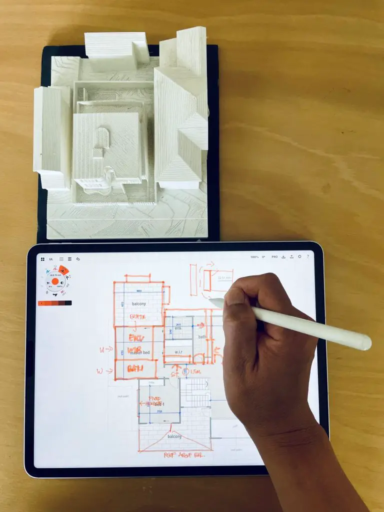
Concepts – As an architect, it is essential to have a tool with the flexibility of a traditional pen on paper but with the speed and versatility of a digital drawing tool for mobility and ease of outputs. Concepts app allows me to sketch and draw with accurate representation in scale and detail, it is much more versatile in presenting ideas and designs to clients and builders in a rapid fashion during meetings and site inspections. It has allow me to skip the conventional and time consuming way of “draw and scan” in documenting ideas.
Concepts on ipad – a mobile tool offering fast and convenient way in sketching with multitude array of medium and graphical representation.
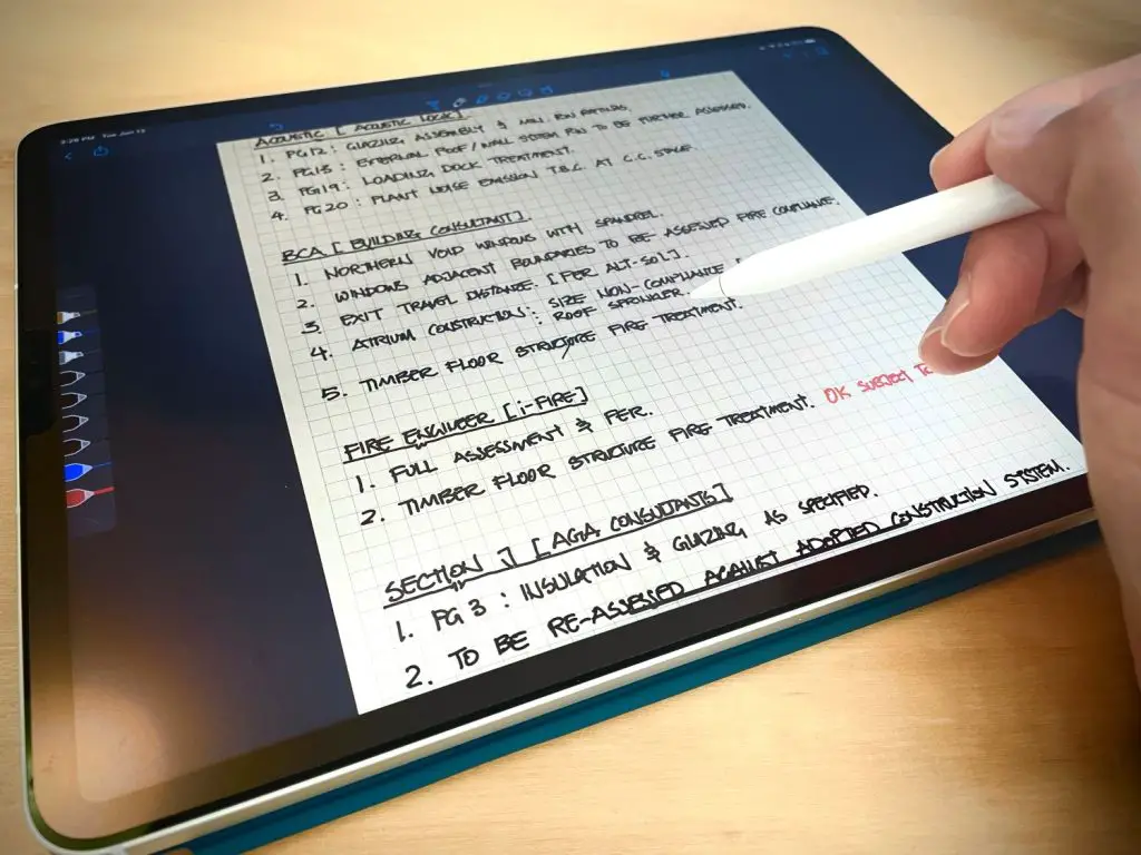
Notability – Note taking and writing is a frequent task in daily routine of an architect. I use Notability on daily basis from capturing meeting minutes on sites to simple task such as writing down projects punch lists. The app also allows user to scribble diagrams and simple sketches on sides which can be easily exported as PDF document together with the written notes.
Notability – a must have for architects seeking paperless and mobile writing pad.
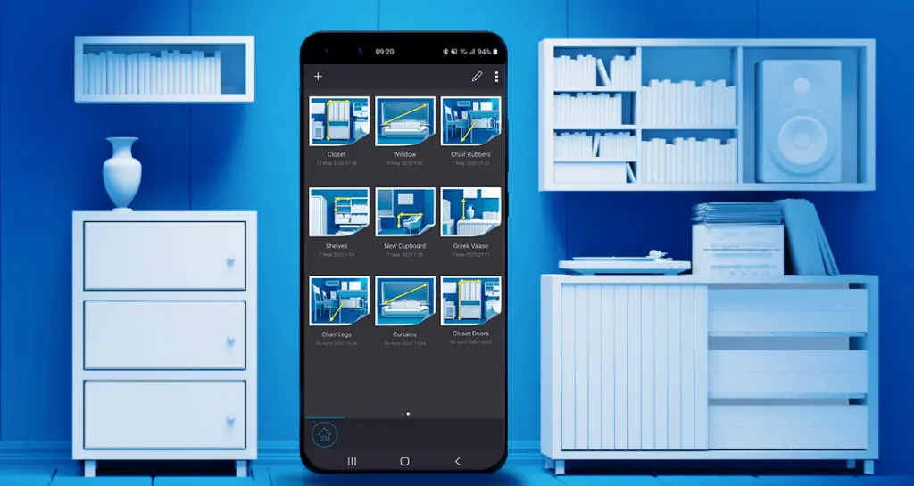
My Measures– this measuring app provides a no frill approach to capturing measurements, notes, angles and images on project sites. It works on both tablets and smart phones with easy to access annotation tools to add dimensions and angles to photos taken on site. The results can be printed, share or save to your projects in PDF format.
My Measures – coupled with a laser measuring tool, this app provides a swift medium to record notes and measurements on project sites.
I love to hear about your experience – Let us know in the comment section below – Have you tried any of the above mentioned apps? Any other apps you can recommend to me and our readers to try?
Important: While we don't collect cookies, some of our 3rd-party services (such as PayPal and WordPress) do, to give you a safer and better browsing experience. Read about how we use cookies and keep your personal information secure by reading our Privacy Policy here.