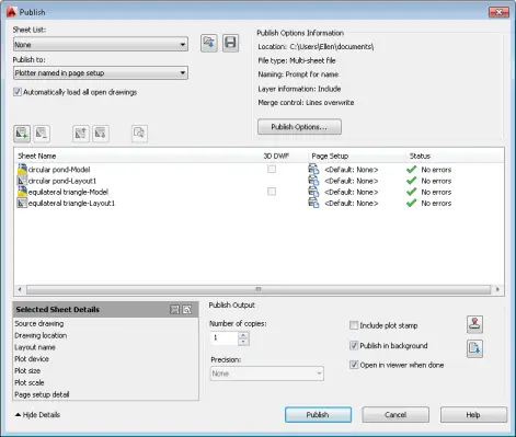
The PUBLISH command creates the multi-page DWF, DWFx, or PDF files. You can also use the command to batch plot to a plotter. This command gives you a lot of flexibility to choose which drawings to output.
Be sure to save your drawing before using the PUBLISH command.
Choose Output tab > Plot panel> Batch Plot to open the Publish dialog box. The dialog box displays the model and layout tabs of the current drawing or all open drawings. To list only the tabs of the current drawing, uncheck the Automatically Load All Open Drawings check box in the Publish dialog box. (This is controlled by the PUBLISHALLSHEETS system variable.) If you see the Status message, “Layout not initialized,” cancel and display the layout tab; then start the PUBLISH command again.
To add other drawings and layouts that you want to include in the drawing list. do any of the following:
I have lost my menus such as draw, render, etc. Everything that would allow me to copy, move, trim etc. I don’t have anything that will allow me to enter commands. Also my menu bar ie. file, window, help. The command line at the bottom of the drawing is also gone.
Since I didn’t see the viewer’s screen, I can’t be sure what happened. Maybe his menu was unloaded. (In that case, try the MENULOAD command.) But it could also describe the Clean Screen feature–although Clean Screen keeps the command line.
The Clean Screen feature in AutoCAD hides as much as possible of your screen, giving you maximum room for drawing. It doesn’t turn everything off on your screen, but almost everything. Here’s what’s left:
Status bar
Menu bar (if you have it displayed)
Command line
Here’s what my screen looks like with Clean Screen on.
Clean Screen is great for keyboard jockeys who like to type in commands and aliases. (“We don’t need no stinkin’ ribbon!” to paraphrase “The Treasure of the Sierra Madre.”)
To turn on Clean Screen, click the Clean Screen button at the right end of the status bar (it looks like a box) or press Ctrl + 0. Repeat the process to turn Clean Screen off. The actual command names are CLEANSCREENON and CLEANSCREENOFF.
It’s common to need to place a circle in the middle of a rectangle, especially in mechanical drawings. It’s easy to do using object snap tracking.
Object snap tracking tracks the coordinates on object snaps and for this task, you need to track the midpoint of the rectangle’s sides. Here are the steps:
Make sure that the Object Snap Tracking button on the status bar is on, or press F11.
Make sure the midpoint object snap is on or press F3.
Right-click the Object Snap button on the status bar and choose Midpoint, if it isn’t already highlighted. This sets a running object snap for midpoints.
Draw a rectangle (RECTANG command).
Start the CIRCLE command.
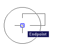
At the Specify center point for circle or [3P/2P/Ttr (tan tan radius)]: prompt, pass the cursor over one midpoint of a rectangle side until you see it marked. This is called acquiring the object snap.
Move the cursor toward the center of the rectangle and then pass the cursor over a rectangle side that is perpendicular to the first side, to acquire that sides midpoint.
Move the cursor toward the center of the rectangle until you see the tracking lines from both midpoints cross each other at the rectangle’s center.
Click to specify the circle’s center.
At the Specify radius of circle or [Diameter]: prompt, specify the circle’s radius.
Watch the video to see how it’s done!
One of our readers, Andrew, mentions another good method, using Mid between 2 points Osnap, to achieve the same thing:
Draw your rectangle.
Start the circle command.
+ right click.
Choose Mid between 2 Points.
Turn on osnap if it is not already on. (need either mid point snap or end point)
Choose the mid point on two opposite sides or two of the opposite corners.
The VIEWBASE command, new for AutoCAD 2012, automates the process of creating 2D views of 3D models. This command creates 2D view objects, which are a little like viewports, but actually a completely separate type of object. In fact, when you display a layout, the first thing you do is delete the default viewport and start from scratch.
2D view objects have been updated in 2013 to let you create details and sections. The new commands are VIEWDETAIL and VIEWSECTION.
At the end of this tip, you can watch a video of the process of creating 4 views, plus a section and a detail.
You start by placing at least one 2D view object, because the details and sections are taken from an existing 2D view object.
Create a section view
A section view cuts through the middle of a model. To create a section view, you should be in the 3D Modeling workspace and be on a layout that has an existing 2D view object. Then follow these steps:
Choose Layout tab> Create View panel> Section drop-down menu and choose the style of section line you want. Your choices are Full, Half, Offset, and Aligned. This starts the VIEWSECTION command.
At the Select parent view: prompt, click the 2D base object that you want to use for the section.
At the Specify start point: prompt, pick the point for the start of the section.
At the Specify end point: prompt, pick the point for the end of the section. The command adds section lines and an identifer letter.
At the Specify location of section view: prompt, place the section.
You can edit the label and change its font, size, etc.
Create a detail
A detail focuses on a small part of your model. To create a detail, follow these steps:
Choose Layout tab> Create View panel> Detail drop-down menu and choose either Circular or Rectangular. This starts the VIEWDETAIL command.
At the Select parent view: prompt, pick the view you want to use for the detail.
At the Specify center point: prompt, pick a center for the detail.
At the Specify size of boundary or [Rectangular/Undo]: prompt, pick a point on the border of the detail to specify its size.
At the Specify location of detail view: prompt, place the detail.
Use the command options
Both commands have options. Here are some of them:
Hidden lines lets you specify a shading type
Scale lets you specify a scale
Visibility lets you turn on and off inteference edges, tangent edges, sheet metal bend extent lines, thread lines, and presentation trails. Some of these options are inherited from Inventor files, which you can use to create 2D view objects. They might not be available for your model.
Annotation lets you specifier the identifier (the letter) and turn off the label.
Hatch lets you turn hatching on or off
Here’s a video showing the process of creating 2D views, a detail, and a section.
Do you use these features? Or do you use another method of creating 2D views from 3D models? If so, why? Leave a comment!
Suppose that you would like to insert a label that displays the area of an enclosed figure. While the AREA command can show you the area, it doesn’t create a label in your drawing. If you insert the area at the end of a leader, that area doesn’t change if your object changes in size.
You can use fields (introduced in AutoCAD 2006) to display information about objects. In this tutorial, you create a leader that displays the area of a tub. You can do this in model space or paper space.
Set up a text style for your leader text and a dimension style for the leader.
Start the MLEADER or QLEADER command.
Specify the first leader points and subsequent points until you see a text cursor.
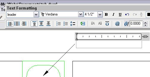
If you’re using the QLEADER command, At the Specify text width <0″>: prompt, specify the endpoint of the text, leaving enough room for the expected text. At the Enter first line of annotation text <Mtext>: prompt, press Enter to open the Multiline Text Editor, as shown here.
Tips from our reader: To get rid of the text box gray hatch, use Tools -> Options -> User Preferences and uncheck “Display background of fields” under “Fields”
For either command, when you see the text cursor, type Area: and a space.
Right-click in the text area and choose Insert Field.
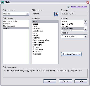
In the Field dialog box, choose Objects from the Field Category drop-down list. This makes the field you want easier to find.
Choose Object in the Field Names box.
In the Object Type area, click the Select Objects button.
You return to your drawing, where you should select the object. The Field dialog box comes back and it should look like the one you see here.
Note: If your enclosed area isn’t one object, you may be able to use the BOUNDARY command to create a polyline. That’s what I did with the tub.
Choose the property you want to display. I chose Area.
Choose a format; I chose Architectural.
Click OK.
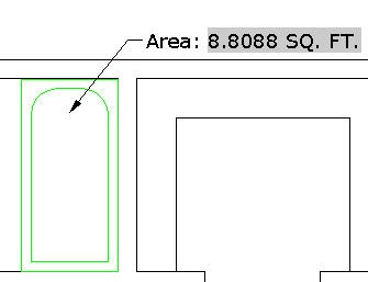
If necessary, adjust the width of the text by dragging on the edge of the Multiline Text Editor’s ruler.
Click outside the editor to close it. Here you see the result.
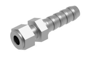
The revolve command or tool is a 3D modeling method that enables the user to create a solid following a certain path with a central axis, think of the ARRAY tool, only in three-dimension.
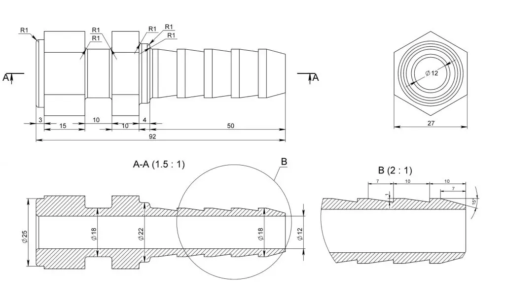
Let’s start by preparing the drawing by specifying crucial dimensions such as the inner and outer diameter of the threaded screw. Prepare the cross-section as well.
1. Open a new drawing. Insert the plan into the top view and cross-section. Make sure they are closed polylines and note the centerline or reference point for the object. 2. Switch to Elevation (Front) then adapt the UCS to snap the section into the inner diameter. 3. From there switch to 3d Isometric. Use the REVOLVE command. Click the Polyline (Elevation). Then trace the direction of the parallel axis line (vertical or horizontal) in the center. Enter 360 as the value of rotation. You now have a complete screw 4. Note that, the parts where there are hexagonal washers, we can trim it by switching to the UCS parallel to the head of the screw and subtract excess from the circle.
You can also do the hexagonal solids separately then assemble and combine it. That’s it! Your 3d screw is now complete.
Any questions about this tutorial? Do you have any tips to help make this tutorial easier? Did you find this tutorial helpful? Leave a comment! And please share the knowledge using the Share buttons below!
Copying objects from one drawing to another is a common task. You can use the Windows Clipboard and the drag-and-drop methods.
When working with 2 drawings open, choose View tab> Windows panel> Tile Vertically (or Horizontally) to view both drawings at the same time.
Note 1 : You can use these techniques within a drawing as well, but the COPY command provides more options and accuracy.
Note 2: You may need to clear your clipboard if having problem pasting latest copied object. (Right click on Desktop – Display setting – Clipboard)
Use the Windows Clipboard to copy objects between drawings
Most people know that they can copy objects in a drawing to the Windows Clipboard and then paste those objects in another drawing. But there are a couple of tricks to this process that can make your work go more quickly and provide more accurate results.
Of course, you can use the common Windowskeyboard shortcuts:
Ctrl+C to copy
Ctrl+V to paste
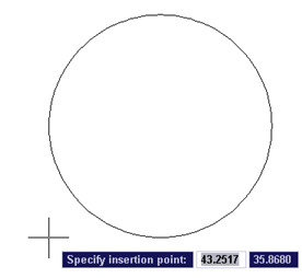
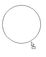
When you use the simple copy-and-paste procedure, you don’t have much control over the placement of your object in the second drawing. That’s because this process uses the lower-left corner of the extents of the object as the base point, which may not be useful. For example, here you see this process with a circle.
As you can see, the base point isn’t on the circle, making it difficult to place the circle accurately.
Therefore, AutoCAD provides you with 2 special tools for copying and pasting.
The first is Copy with Basepoint. Follow these steps:
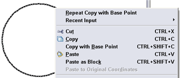
Hover the cursor over the object and right-click to display the shortcut menu. For multiple objects, select them first, and then right-click.
Choose (Clipboard,) Copy with Base Point. This is the COPYBASE command. As you can see in the figure, you can also press Ctrl+Shift+C.
At the Specify base point: prompt, use an object snap to specify the base point.
Click in the other drawing.
Paste, using Ctrl+V, or by clicking Paste on the Standard toolbar. You can also right-click and choose (Clipboard,) Paste from the shortcut menu.
Your cursor is now at the base point you specified, so you can accurately place the object. Specify the insertion point you want.
Here, the base point was set to the center of the circle.
## Dynamic block is another great productivity tip to master. Sign up below to get your Free tutorial on creating a complete dynamic block, including a drawing to practice on. You’ll make a movable chair, resizable desk, and more.
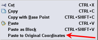
The 2nd useful tool is Paste to Original Coordinates. If you have two drawings that are very similar, you can use this feature to place the object at the same coordinates as in the original drawing.
Just copy the object(s) to the Clipboard, and activate the 2nd drawing. Then right-click and choose (Clipboard,) Paste to Original Coordinates.
If those coordinates are not in the current display, do a Zoom Extents to see the pasted object.
Note: We receive few comments that “Paste to Original Coordinates” may not work on Mac computer. One of our followers (Thanks @Chilli ) provided the following work around.
If you do not have the Clipboard menu option of ‘pasting to original coordinates’, simply follow these steps.
1. Select elements in the proposed property drawing. 2. Right click – clipboard>Copy with base point 3. Type in 0,0 4. Switch to destination drawing 5. Right-click on open area>clipboard>paste with base point 6. Type in 0,0
And if the coordinate system is the same in both drawings, your elements should be located correctly.
Use drag-and-drop to copy objects between drawings
Drag-and-drop doesn’t give you the same control over placement, but it’s a quick way to copy objects. Note that AutoCAD automatically copies objects from drawing to drawing, so that you don’t need to press Ctrl as you drag.
To copy, select the object or objects. Then click the object and hold down the mouse button until you see the drag-and-drop cursor. The only gotcha is that you need to make sure that you don’t click on a grip, because that will just make the grip hot.
Then drag the cursor to the other drawing and release the mouse button to place the object. You’ll probably need to adjust the placement, using the MOVE command, or by using grip-editing.
Xrefs (external references) let you view another drawing within your current drawing without actually inserting that other drawing thus keeping the original drawing size manageable.
Another benefit of using Xref is that changes made to the referenced drawings are automatically reflected in the current drawing when it’s opened or if the xref is reloaded. This will significantly reduce drafting time as well as minimize mistakes.
When working with external references in AutoCad, you may experience some difficulties and problems. Since XREF is one of the most common functions in AutoCad drafting, let’s look into each of these problems and more importantly the easy solutions to these six common Xref problems:
1. Deleting an XREF
To delete an existing XREF, first make sure that there are no objects in the layer. It is also not possible to delete the current layer, Layer 0, Defpoints and XREF dependent layers. Input the LAYDEL command to delete specific layers within the drawing. Type in LAYDEL, then press, Enter. You will be prompted to either SELECT the object or delete by choosing the NAME layer.
2. Exploding an XREF
To successfully export a cad file without the XREF, you will need to BIND the XREF to the drawing. By typing BIND and selecting the XREF, you will be able to convert the XREF to block. The only downside here is that any changes you wish to make in the main XREF file won’t affect the current XREF block. BIND lets the existing XREF to inherit characteristics of a typical BLOCK enabling you to explode it.
3. Change XREF color, set layers to 0
If you are looking to change the layer, line weight, and color of a referenced file without turning it into a block or editing the whole file, you can use VISRETAIN. Access the main XREF file and type in VISRETAIN. Enter values as desired (VISRETAIN=0 means that you can configure the properties of the drawing while setting it to VISRETAIN=1 means it retains its settings same as the mother file no matter what).
Another option is changing the xref’s layers color in Layer Properties Manager. This allow customization of each layer of the main xref file – not limited to colors but also linetypes etc. For additional productivity tips to work more effectively with layers, check out our blog – Tips for working with layers.
4. Detach and XREF File (and all at once)
To detach a specific file from the current drawing file, access External References from the VIEW tab or type XREF on the command line, hit Enter. From the XREF panel, select a drawing reference, right-click. A list of options will appear from the cursor, select Detach from the menu. In the cases of having a lot of XREF to detach, such in the cases of big projects, you may opt to detach the files altogether with one click. To be able to do so, you need to UNLOAD THE file and hold the shift key down while selecting the XREFs to be deleted. See here:
5. Setting the same measurement units for the XREF File and current drawing
Enter INSUNITS in the command bar and turn it to zero, this makes your XREF unitless (by default, 1- imperial ; 4- metric). Set values for your INSUNITSDEFSOURCE and INSUNITSDEFTARGET to 0 as to make both the source file and destination file both unitless.
6. Toggle XREF Snapping
Turning the snap on a referenced drawing is possible though not usually recommended. By moving the XREF to defpoints and freeze layer 0, you will turn the XREF to an overlay on the background and render it unusable for snap and selection. To regain its previous functions, just thaw the layer and it will be usable again.
What are your top Xref problems? Do you have other Xref related issues and solutions you want to share?
Sometimes people have trouble displaying a toolbar that isn’t visible, or a toolbar seems to disappear for no apparent reason. Here are some tips for displaying toolbars.
1st method
The easiest way to display a toolbar is to right-click any visible toolbar. This displays the list of all your toolbars, as you see here on the right. Just pick the one you want to make it visible.
However, certain custom toolbars, and the Express Toolbars aren’t listed. To find them, right-click any blank (gray) area next to a toolbar. Click ACAD to find the same toolbars you’d get by right-clicking a displayed toolbar.
Tips: If all your menu has disappeared, quickest thing to try out first is to use MENULOAD command to reload the menu. Also make sure to Choose Classic as the workspace
2nd method
If you know the name of the toolbar, another option is to use the command line form of the TOOLBAR command, by typing -toolbar. At the resulting prompt, enter the name of the toolbar. Then, at the Enter an option: prompt, press Enter to show the default option, which is Show. Here’s what it looks like:
Command: -toolbar Enter toolbar name or [ALL]: dimension Enter an option [Show/Hide/Left/Right/Top/Bottom/Float] <Show>:
## Dynamic block is another great productivity tip to master. Sign up below to get your Free tutorial on creating a complete dynamic block, including a drawing to practice on. You’ll make a movable chair, resizable desk, and more.
3rd method
An alternative is to choose View> Toolbars. Starting with AutoCAD 2006, this opens the Customize User Interface (CUI) dialog box. As you can see, the On By Default value is Hide. Click to reveal a drop-down arrow, and choose Show to display that toolbar by default.
4th method
An excellent way to control the display of toolbars is with workspaces. You can create a workspace that displays any set of menus, toolbars, and palettes (called dockable windows in the CUI dialog box). You can do this in 2 ways.
Display the toolbars that you want. In the Workspaces toolbar, choose Save Current As from the drop-down list. Enter a name and choose Save. Now, you can choose that workspace any time you want it from the Workspace toolbar (assuming you can find the Workspace toolbar!).
You can also create a workspace in the CUI dialog box. Right-click the Workspaces node and choose New> Workspace. Then type the name of the workspace. Click the Customize Workspace button. What this does is add a checkbox next to all the items on the left. Then you check what you want and uncheck what you don’t want. For each item, you can specify its properties, such as Docked or Floating. Finally, click Done.
Finding lost toolbars
Toolbars can sometimes get “lost” due to a change in screen resolution. If you recently changed the resolution of your screen, try a higher resolution, which will show more items at the edge.
You can protect toolbars from moving by locking their position. Right-click any toolbar and choose Lock Location. Then choose Floating Toolbars to lock those that aren’t docked, Docked Toolbars, or All.
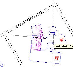
Sometimes you need to rotate a block or object to match the angle of an existing object. Here’s one way to accomplish that, using the Reference option of the ROTATE command.
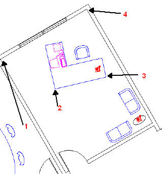
In this example, you want to rotate the desk to match the rotation of the end wall. Follow these steps:
Start the ROTATE command and select the objects that you want to rotate.
At the Specify base point: prompt, specify the base point of the object you want to reference to, not the base point of the object you want to rotate. This is point 1 in the above figure.
At the Specify rotation angle or [Reference]: prompt, choose the Reference option.
At the Specify the reference angle <0>: prompt, pick the point on the object that you want to rotate that corresponds to the base point you just specified. This is point 2 in the figure.
At the Specify second point: prompt, pick the second point that, together with the previous point, specifies the angle of the object that you want to rotate. This is point 3 in the figure. Notice the rubber band line from your base point (point 1) connecting to your object as you move the cursor, as shown below:
At the Specify the new angle: prompt, pick the point on the reference object that, together with its base point, specifies the angle of the reference object. This is point 4 in the first figure.
## Dynamic block is another great productivity tip to master. Sign up below to get your Free tutorial on creating a complete dynamic block, including a drawing to practice on. You’ll make a movable chair, resizable desk, and more.
Sanjay Kulkarni suggests another way to use the Reference option of the ROTATE command and end up with the same result. Sanjay is a technical writer, CAD trainer & programmer, and consultant based in Pune, India.
Use Reference option of ROTATE command
Start the ROTATE command and select the objects that you want to rotate.
At the Specify base point: prompt, specify the base point of the object that you want to rotate. In the top image, that would be point 2.
At the Specify rotation angle or [Reference]: prompt, choose the Reference option.
At the Specify the reference angle <0>: prompt, pick the point on the object that you want to rotate that corresponds to the base point you just specified. This is point 2 in the figure. So you’re picking point 2 again.
At the Specify second point: prompt, pick the second point that, together with the previous point, specifies the angle of the object that you want to rotate. This is point 3 in the figure.
At the Specify the new angle: prompt, choose the Parallel object snap. (Shift + right-click and choose Parallel) This OSNAP works in an interesting way, something like acquiring a tracking point. Move the cursor over the line you want to align to, in this case the line from points 1 to 4. Then move the cursor around to rotate the desk until you see a dotted extension line. You’ll feel the desk “snap” along that line. Then click to complete the ROTATE command.
New Update – Use ALIGN command
A few of you commented that ALIGN command is a more intuitive option, with less steps to achieve the same result. And you do not need to reposition the object. With ALIGN command, remember that “Source” is the object, “Destination” is the reference line.
Type in ALIGN command and select the object that you want to rotate.
At Specify first source point: Click the base point of the object that you want to rotate.
Then select first destination point, which can be at any point of the reference line of which you wish the object to align to.
Repeat and specify second source point: click the end point of the object you wish to rotate.
At specify second destination point, click another point along the reference line.
Then select CONTINUE. And as we do not wish to change the scale of the object with this example, select NO then ENTER
Trim the circle in half and use PEDIT
Jon e-mailed me with the following additional solution: If you use a circle and trim it in half, pedit that, you can then give the resulting pline arc thickness, mirror it and pedit join it into a circle.
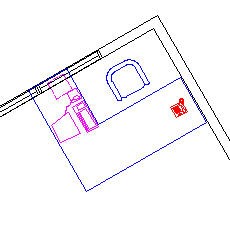
The selected object rotates to match the angle of your reference object, as you see here. Then move the object to its proper location.
Which method do you use? Or do you have another method? Leave a comment!
Important: While we don't collect cookies, some of our 3rd-party services (such as PayPal and WordPress) do, to give you a safer and better browsing experience. Read about how we use cookies and keep your personal information secure by reading our Privacy Policy here.