
Simple linetypes allow you to apply a repeating series of dashes, dots, and spaces to your objects. Complex linetypes can also include text or shapes.
Recently, a reader said that his linetype was defined as dash-dot but displayed as a continuous linetype. If you have this situation, zoom in and see if you can see the dots and dashes.
If you find that the linetype patterns in your drawing are too long or short, the line might look continuous. How often the pattern is repeated is affected by three factors:
- The linetype definition itself
- The global linetype scale
- The object linetype scale
1. Use a different linetype definition
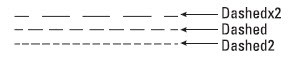 One choice is to change the linetype. A number of linetypes come in short, medium, and long variations, such as Dashedx2, Dashed, and Dashed2, as you see here.
Note: If you use ISO linetypes, the pattern definitions are much longer than the other linetype definitions, so you may need to make adjustments to the linetype scale.
2. Change the global linetype scale
Another choice is to change the global linetype scale, which affects all noncontinuous linetypes in your drawing. AutoCAD multiplies the linetype definition by the global linetype scale to calculate the length of each repetition of the linetype:
- Linetype scales larger than 1 result in longer sections — and fewer repetitions of the linetype definition
- Linetype scales less than 1 result in shorter sections — and more repetitions of the linetype definition
Here you see 3 versions of a drawing with linetypes at linetype scales of 0.5, 1, and 2. As you can see, a scale of 2 is too large and a scale of 0.5 is too small. A scale of 1 is just right.
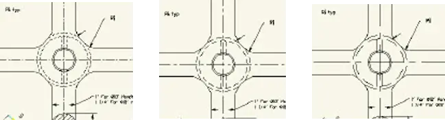
When you draw, you just want to be able to distinguish the linetype both when you can see the entire drawing on the screen and when you zoom in close. The main reason to scale linetypes is for plotting. A linetype scale that works for a drawing of a house while you’re drawing may look continuous when you plot it at a scale factor of 1 = 192.
When plotting, first try the plotting scale factor for the linetype scale. If that doesn’t give you the results you want, try 1/4 or 1/2 of the scale factor — in the 1 = 192 example, you could try a linetype scale of 96 or 48.
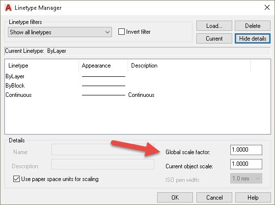
To change the linetype scale, click the Linetype drop-down list in the Properties panel of the Home tab and choose Other to open the Linetype Manager. Click Show Details if the lower portion of the dialog box isn’t displayed.
In the Global Scale Factor text box, type the scale factor that you want. Click OK. The drawing regenerates, changing the scale of every noncontinuous linetype in the drawing.
Tip: The global linetype scale is stored in the LTSCALE system variable. You can change the linetype scale by typing ltscale on the command line and typing a scale.
3. Change the object linetype scale
Sometimes you may want the linetype spacing to be different for just 1 or 2 objects. Maybe an object is too small to show the linetype clearly.
To change the linetype scale, open the Linetype Manager. Click Show Details if necessary and in the Current Object Scale text box, type the scale factor you want. Click OK. Now all objects that you draw use the current object linetype scale. When you’re done drawing objects at that linetype scale, remember to change the linetype scale back to 1.
Tip: The current object linetype scale is held in the CELTSCALE system variable. You can also change the current object linetype scale by typing celtscale on the command line and typing a scale.
If you have also set the global linetype scale to a value other than 1, AutoCAD multiplies the 2 linetype scales. So if you have a global linetype scale of 12 and a current object linetype scale of 0.5, objects you draw will have a linetype scale of 6.
To change an existing object’s linetype scale, select the object and open the Properties palette. Click Linetype Scale and then type the new linetype scale. This linetype scale affects only the selected object. It does not affect the global linetype scale.
Have linetype scales frustrated you? Do you have any tips you can share? Leave a comment! And please use the Share buttons to share this with your colleagues.

- Combine or subtract 2D shapes to create custom shapes - February 17, 2022
- Working with linetype scales - January 18, 2022
- Rename named objects–blocks, dimension styles, layers, and more - December 21, 2021


If your dash length appears fine in ModelSpace but not correctly in some viewports, don’t forget about the PSLTSCALE system variable setting. If you have viewports at different scales on one Layout Tab, or some details in PaperSpace and some scaled viewports on the same Layout, you’ll want a PSLTSCALE setting of 1 and then your LTSCALE will need to change to either 1 or .5 based on your office standards. This SysVar needs to be set in each Layout Tab – it isn’t a global system variable. There are LISP routines available to help manage drawings with many layouts if you need to switch them over en masse.
Also, if you have the habit of “drawing through the viewport” into ModelSpace from PaperSpace on a Layout Tab, make sure you didn’t actually draw your linework in PaperSpace when you thought you drew it in ModelSpace. Your dashes will appear continuous when all your other settings are correct.
Additionally, check your MSLTSCALE system variable setting (0 vs 1). This SysVar controls the scaling of linetypes in ModelSpace based on the annotation scale.
Theresa, thanks, good points!
I draw in model space and plot in paper space. I want to see the lines in model space as they will appear in paperspace – the ‘ole “what you see is what you get”. My drawing in model space may contain several drawings, each to be plotted at a different scale.
Here is how I handle my linetypes.
1. I go to the linetype manager (LT) and uncheck the box that says “Use paper space units for scaling.” I change the global scale factor to a number that is 1/2 of the plot scale factor for the main drawing. For example, if my main drawing is a floor plan, which will plot at 1/4″ = 1′-0″, I set the global scale factor to 1/2 x 48 = 24. Here, 48 is the scale factor for 1/4″ scale: 4 x 12 = 48. Why AutoCad does it this way is beyond me, but that’s how it works. It’s always been that way.
2. Now, let’s say I want to put a detail in model space with this floor plan. I want to plot this detail at 3/4″ = 1’-0″. (The scale factor for 3/4″ is 16, but remember, for linetypes we have to divide that in half, so the “linetype” scale factor will be 8.)
3. I start drawing the detail. When I make the first dashed line – or anything but a “continuous” line – initially it will appear solid. To scale it: I open the properties windows and, with the line selected, I change the scale factor to – guess what? .33! To get that number I take the linetype scale that the drawing is set to – which remember is 24 and I divide that number into my new detail scale of 8. 8/24 = .33 Wala!
4. Make a viewport in paperspace for each detail, scale them as discussed and the lines will look exactly the same. You may not want them to look the same and so you will need to make adjustments, but that gives you a starting point.
5. You will need to regenerate the drawing to get the linetype to show up properly – at least I always do.
Patricia, wow that’s a lot of work — and calculations! Thanks for sharing your process.
I draw pavement marking plans, typically at scales ranging from 1”=10’ to 1”=40’. I’ve created linetypes with 1:1 definitions for pavement marking patterns, i.e. 10,-30 for a 10 foot stripe and 30 foot gap.
What I’ve done for years is set the individual linetype scales of the pavement marking entities to 1/(drawing Ltscale) and set PSltscale and Msltscale to 0. This gives me the result I want – the pavement markings show up with the correct stripe and gap lengths. It’s basically the opposite of Autocad linetype scaling, giving consistent scaled measurements regardless of plan scale.
If I need to work at multiple viewport scales in a single drawing I typically set the drawing Ltscale to 20, regardless of the different actual scales being used; then set the linetype scale of the individual pavement marking entities to 0.05 (1/20).
Now I’m working as a sub to another consultant that uses annotative scales, and they want my drawings to display properly when Ltscale, PSltscale and Msltscale are all 1.
I can get it to work for a drawing where everything will be plotted at the same scale. But I can’t get the linetypes to look consistent in one drawing that has multiple viewports at different scales.
Is there any other way to handle this, built into autocad? For example a Ltscale setting that would be 1/(annotationnscale), so it would be dynamic for different annotative scales?
I thought the purpose of PS is to essentially show how it will plot, minus layer colors etc. I cannot understand why the line type scale of my property line is allowed to display one way in PS and plot entirely differently. Autodesk has made this entire line/celt/ps scaling issue MUCH too complicated. Any insight would be appreciated.
Have any command to apply selected objected like revision cloud will apply one time in many selected object.