
This is a guest post by Viktor Rask, founder of CAD Mode and author of the e-book 101 CAD Exercises – Learn & Improve Your Skills. He is a mechanical engineer (BSc.) with a passion for CAD and 3D! He also loves to help others grow.
* * * * *
 When I first started to learn CAD a few years back, I had a major problem with my learning process. I couldn’t find any exercise material. I searched and searched but couldn’t find anything useful. I decided to create the 101 CAD Exercises book to help others speed up their learning process and make it more hands-on and fun. If you want more exercises like this, you can get them here. (The exercises are 2D and 3D drawings without instructions so that they are not specific to AutoCAD.)
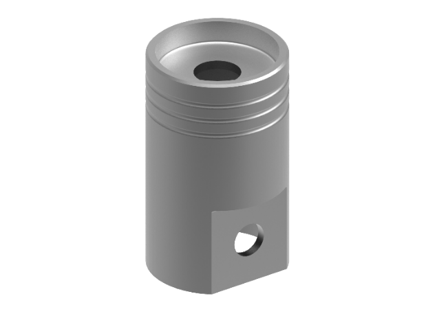
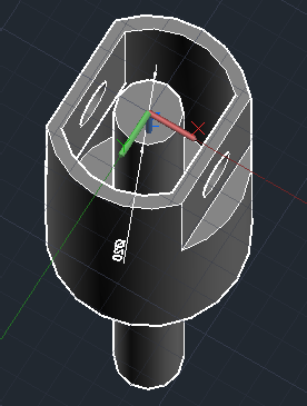
In this tutorial, you will learn how to create a piston using 3D geometry in AutoCAD. To do this you will use the 2D drafting and annotations and the 3D features. I assume that you are already a bit familiar with the basic 2D drawing commands such as LINE, CIRCLE, TRIM, etc. The final model should look something like this in 3D.
Here are the 2D drawings:
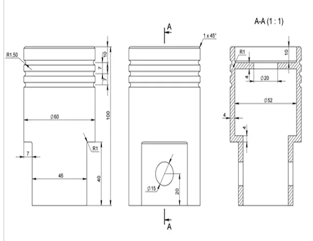
Remember that using gridmode (F9) and snapmode (F7) can be helpful between drawing tasks. For this exercise, I’ve been using AutoCAD 2017 but it will work with previous versions as well as other CAD software. Your commands and shortcuts might differ with other versions, though. The dimensions that are used in this exercise are originally metric but since it’s all proportional you can use the same values but with imperial units instead. I’ve decided to keep the measurements unitless for this exact reason.
- Start a new drawing in AutoCAD.
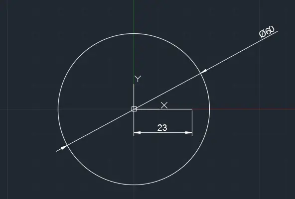
- Draw a circle with a diameter of 60 and place its center on the origin (0,0).
- Draw a horizontal line that starts at the origin and a length of 23. This line will be used as a reference length for the next step.
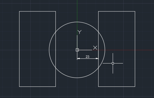
- Draw a rectangle using the RECTANG command as shown on the right side of the image below, using the endpoint of the line as a guide to place the rectangle. The dimensions of the rectangle don’t need to be exact but they must exceed the circle perimeter as we use it as a cutter. Then mirror the rectangle using the start point of the line (or the center of the circle) for the mirror line. Remember to erase the reference line that you used to create the rectangle.
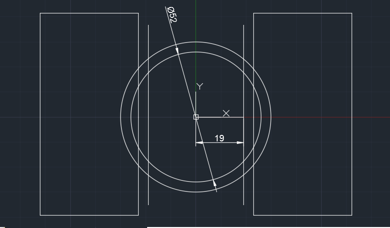
- Now draw a concentric smaller circle with a diameter of 52. Also, draw a vertical line 19 units to the right of the center of the circles as shown below and mirror it. As with the rectangles, the lines need to exceed the circle perimeter.
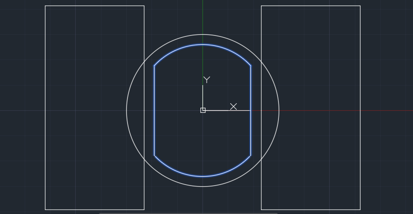
- Now use the TRIM command and use the vertical lines as edges to trim the inner circle. Resize the 2 vertical lines so that they end at the top and bottom arcs. Then use the JOIN command to make the following shape in the center.
- Click the gear (Workspace Switching) icon on the bottom right of the screen and choose 3D Basics instead of Drafting and Annotation. Also choose a 3D viewpoint so you aren’t looking at plan view.
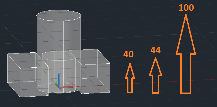
- Now use the EXTRUDE command to extrude the shapes to make a 3D model. The Z dimensions (shown below) are 40 units for the rectangles, 44 units for the central shape, and100 units for the circle. This image is using the X-ray visual style.
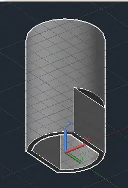
- Now start the SUBTRACT command and subtract every shape from the main cylinder. Remember that first you must select the main cylinder, press Enter and then select the objects you want to subtract from it. You might need to change your viewpoint or visual style, especially to subtract the central shape. Now you should have a model looking like this:
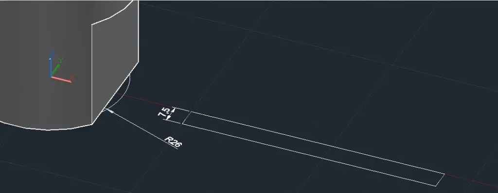
- Now you should go back to the 2D Drawing and Annotation and return to a top 3D view such as SE Isometric if necessary. Draw a concentric circle with a diameter of 52 and a rectangle (using the RECTANG command) with a height of 7.5 and one of its sides on the x-axis as shown in the image. The length of the rectangle should exceed the cylinder diameter, which is 60.
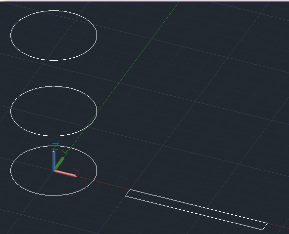
- You can isolate (hide) the main body by right-clicking on it and choosing Hide or Isolate>Hide. Then use the COPY command to create two more circles, 44 units and 100 units in the z-direction. After this, delete the base circle. Go back to the 3D Basics workspace.
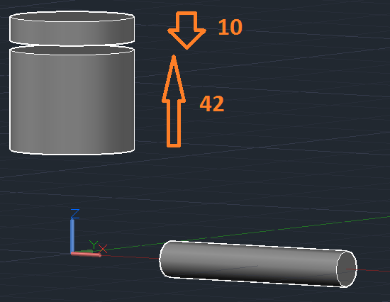
- Use the EXTRUDE command on the 2 circles; the lower circle should be 42 units upwards and the circle on top should be 10 units downwards. Then use the REVOLVE command on the rectangle to make another cylinder. Specify the X axis as the axis of revolution and use the default 360° revolution.
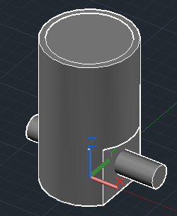
- Now right-click and end object isolation (Unhide). Using the MOVE command, bring the thin cylinder 20 units upwards in the Z-direction and move it towards the main body of the piston so that it extends on both sides.
- Now subtract the 3 cyllinders from the main body. You can use the Bottom view for easier access.
- In the 2D Drawing & Annotations workspace, draw a concentric circle with a diameter of 20 units. Use the EXTRUDE command to create a cylinder that is higher than the main body. Then subtract it from the main body.
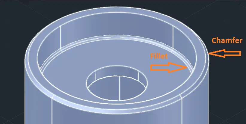
- Now use the CHAMFEREDGE command pick the outer edge of the top face of the cylinder, press Enter and type d to give it a distance from the edge. Choose 1 unit as the distance and then press Enter. You must enter the distance twice to give it the same distance from both edges.
- Start the FILLETEDGE command and then pick the inner edge of the top face of the cylinder, press Enter, and type r to give the fillet a radius. Choose 1 unit as the radius and press Enter.
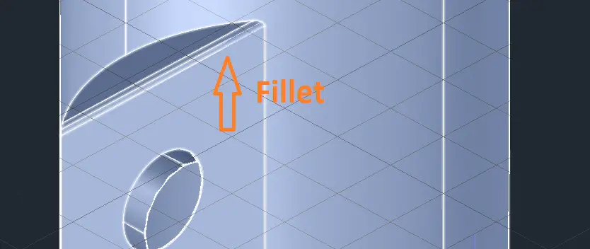
- Next task is to fillet the side faces. Use the same command as in the previous step.
- We will now create the ring pockets on the piston’s outer wall. Use the TORUS command. Set the center of the torus to the origin (0,0) and then use 60 units as the diameter and 3 units as the thickness. Make three copies of the torus (using the COPY command) with the following values in the z-direction: 76, 83 and 90 units.
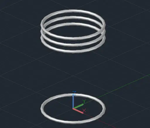
You should delete the first torus. Remember that you can isolate (hide) the main body for this step.
- Finally, subtract the tori (plural of torus) from the main body. You should now have a 3D model that looks like the one at the beginning of this post.
For more drawings that you can use to practice your skills, be sure to check out my book!
If you have any questions you can also email me at viktor@cadmode.com and I’ll do my best to help you out.
![]()
![]()
Do you have any tips to help make this tutorial easier? Did you find this tutorial helpful? Leave a comment! And please share the knowledge using the Share buttons below!

- Combine or subtract 2D shapes to create custom shapes - February 17, 2022
- Working with linetype scales - January 18, 2022
- Rename named objects–blocks, dimension styles, layers, and more - December 21, 2021


Good tutorial. Well thought out and easy to follow.
[…] Read More […]
Very good! Small trouble with diameter vs radius, but I thoroughly enjoyed it and learned a lot!
Thank you for making ths
Great tutorial step by step, very innovative. Keep Posting
ya its very good and understandable thank you very much.
Adhur GYAN hai How to make Solide ??
Step 6:
Convert Arcs to Polyline in order to join successfully.