
 This is a guest post by Ben Richardson. Ben is director of Acuity Training, a UK based IT training business. Acuity Training focuses on high quality classroom-based IT applications training including AutoCAD (of course!), Adobe and Microsoft.
You can’t succeed in 3D drawing without learning how to view your model from various angles. In this tutorial, you will become familiar with AutoCAD’s Isometric views, learning to move and alter AutoCAD objects in 3D. You will do this by creating a simple 3D representation of a door and manipulating it to suit your needs. It isn’t an exact model but will give you the experience you need to create more precise 3D models.unit
1) Specify settings
Before we start, you need to make sure your settings are identical to mine for the tutorial to work.
We’ll be working in inches. If you customarily work in the metric system, type DWGUNITS on the command line and type 1, for inches.
Type UNITS and in the Units dialog box, under Length, Type, choose Architectural and click OK.
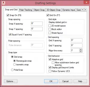
To specify the Snap and Grid settings, right-click the Gridmode button on the Status bar and choose Grid Settings.
Snap and Grid should both be on, set to 6″, as you see on the right. Click OK to close the dialog box.
Also, this tutorial uses the 3D Modeling workspace. To switch, click the Workspace Switching drop-down arrow in the taskbar at the lower-right and choose 3D Modeling.
Note: To Orbit anytime through the tutorial, hold down SHIFT and click on your mouse scroll (middle) wheel/button and drag. Then click on any point of the View Cube to level your perspective.
2) Start drawing a 2D door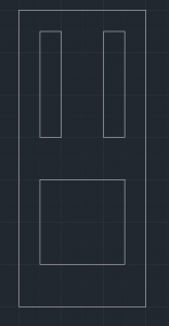

Start by making a 2D door–a rectangle–that is 3 feet wide (3′ or 36″) and 7 feet (7′ or 84″) tall. To do this, use the RECTANG command and make sure your starting point is on one of the major grid points.
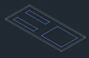
Once you have the rectangle that will form the major border of the door, get to work creating rectangles for the door panels as shown here. Because Snap is on, you don’t need to specify the start and end points by typing. The bottom panel starts 6″,12″ from the lower-left corner of the door and is 24″ x 24″. The bottom edge of the top panels are 12″ above the lower panel and they are 6″ wide and 30″ (2’6″) high.
3) Use the View Cube to switch to an Isometric View
Now we will be heading over to Isometric View. What is an Isometric View? The math is technical, but simply put, you’re looking at your model from a corner viewpoint rather than straight on (from the top, front, back, or bottom, etc.)
The View Cube is an integral part of working isometrically in 3D models in AutoCAD. It is located at the top-right corner of the AutoCAD Window. Click on the bottom-left corner of the cube, also known as the Southwest corner.
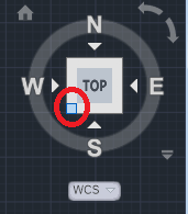
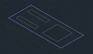
After you click that part of the View Cube, you see a 3D wireframe of your 2D door. This is exactly what is supposed to happen. Now you’re looking at it from one of the corners.
4) Turn the 2D door into a 3D door
You’ll use the PRESSPULL command to turn the 2D door into a 3D door. Type PRESSPULL and press ENTER. The prompt will ask you to make a selection. Select the outer rectangle and press ENTER. This displays a prompt to determine the thickness of the door. Move your mouse cursor upward a little to set the positive direction. Type 1.75″ and press ENTER.
The original rectangle is now a rectangular 3D prism.
5) Create the panels on both sides of the door
The 3 smaller rectangles (the panels) are now along the “back” side of the door. We want the 3 smaller rectangles to be visible on both sides of the door. This next part will be tricky, so pay close attention.
We need to copy these 3 rectangles and make sure they are moved up along the Z-axis. Type CP and press ENTER to start the COPY command. At the “Select Objects” prompt, select the 3 inner rectangles and press Enter to end selection. At the “Specify Base Point” prompt, click any corner of one of the inner rectangles. At the Specify second point prompt, move the cursor upward, and type 1.75. Press Enter again to end the COPY command.
Note: Sometimes, AutoCAD will be stubborn and won’t provide you with access to the Z-axis. In this instance, use these alternative steps:
- Select one of the smaller rectangles, make a copy, and place that copy in the exact location of the original.
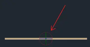
- Click the copy and type 3DMOVE into the command line and hit ENTER.
- Now a new style of cursor will open with 3 arrows, green, blue, and red. Click the blue one, drag your cursor straight up, type 1.75”, and hit ENTER. (If you do not go straight up, following the blue line, the 3DMOVE tool will try to do rotations. If this does happen, just hit ESC and try the command again.)
- Do those 3 steps for each of the 3 small rectangles.
After this, click Top on the View Cube so that it goes back to TOP and the word TOP is right-side-up.
6) Add materials
 We are going to be adding Materials to our door, so it looks like a door and not a bunch of lines. But before these materials will be visible, you have to change the Visibility Mode, which is set to Wireframe by default. This is easy. Go to the Home tab, View panel in the Ribbon. From the Visual Styles drop-down, choose Realistic. (Some versions of AutoCAD will have the Visual Styles Panel on the Visualize Ribbon Tab.)
Your door will now be a grayish-blue if you’re using the default black background. For now, this is what we want. Head over to the Render or Visualize tab in the Ribbon and in the Materials Panel. click Material Browser to open up the Materials Browser.
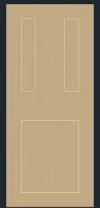
Click on any Material you’d like that it is in the Materials Browser and drag it onto your door. I have chosen a Wood material. (You need Materials installed for this to work.)
7) Imprint 2D faces
Next, we have to pull back the relief on the inner rectangles, that is, we want to indent them. To do this we first need to make the 3 smaller rectangles be recognized as part of the Solid.
I will show you how to do this with one of the 3 rectangles and we will then replicate this process for the other two.
To start type IMPRINT and press ENTER. This command allows you to imprint 2D faces onto a 3D surface and make them part of the 3D surface.
At the “Select a 3D Solid or Surface prompt,” just click on the door, making sure to avoid clicking on any of the 3 small rectangles.
At the “Select an object to imprint” prompt, hover your mouse over the perimeter of the top-left rectangle and click. (If AutoCAD gives you problems with the selection, use Orbit to change the viewpoint a little and try again.)
At the “Delete the Source Object” prompt, type Y and press ENTER. Click the upper-right rectangle and press ENTER, and then do the same with the bottom rectangle. All 3 have now been imprinted and deleted. Press Enter one more time to exit the IMPRINT command.
8) Indent the door panels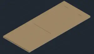

Now click on the bottom-right (Southeast) corner of the View Cube.
Type PRESSPULL and press ENTER. Click inside one of the small rectangles, drag the mouse down, type 0.5″, and press ENTER.
Note: It may be difficult to exactly select the narrower rectangles on the inside. If so, turn off your Snaps (press F9).
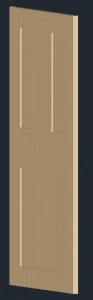
Now repeat this process with the other 2 smaller rectangles. Your door should now look like this.
Flip the view over using either Orbit or the View Cube and then do the same with the small rectangles on the other side of the door, this time dragging up instead of down. Remember to Imprint the rectangles before attempting to do a PushPull of 0.5.
9) Rotate the door

There is one problem left with the door, aside from its missing knob. It is flat on the “floor!” Let’s fix that. Have your View Cube match up with the one you see here.
Now all you have to do is hit CTRL-A to select everything, type in 3DROTATE and hit ENTER. Then click the red circle that it is pointed out here; it will turn yellow. Note: If you don’t see the red circle, try an isometric (corner) view from the Viewcube.
After clicking it, a prompt will appear asking you by how many degrees would you like to rotate the object. We want it upright, so type 90 and press ENTER.
 You can play around with the views of the drawing using Orbit and the View Cube as it pleases you.
Note: Making a knob involves its own whole complicated tutorial.
That was just a rough overview of navigating an AutoCAD file in 3D and constructing something in Isometric View. I hope you enjoyed the tutorial.

- Combine or subtract 2D shapes to create custom shapes - February 17, 2022
- Working with linetype scales - January 18, 2022
- Rename named objects–blocks, dimension styles, layers, and more - December 21, 2021


Thanks for sharing