There are various reasons that you might need to create a circular object with a specific width, such as matching cable widths, or showing cross sections. I’ve come up with 4 ways to go about this. The right one for you will depend on your needs.
Fit a polygon
An excellent method uses the POLYGON command and fits it using the PEDIT command:
Create a 4-sided polygon, using the POLYGON command. You can circumscribe or inscribe it. At the prompt for the radius, enter the radius of the circle that you want. I used a radius of 4. Of course, this creates a square.
Start the PEDIT command, select the polygon, and use the Fit option. Presto! You have a circle. Then use the Width option and specify the width that you want. (I used 0.25.) The result looks bigger, in this case, but still has the same radius of 4.
Use a donut
The DONUT command is very old, but can give you the result you want, especially if you know (or want to calculate) the inner and outer diameter. (Try typing doughnut on the command line. It works!)
Start the command, and specify the inner and outer diameters. Because I wanted the same result as for the previous method, I used 8 and 8.50. Then specify the center. Press Enter to end the command, because you’ll be prompted to place other donuts, and you don’t want too much sugar at once.
Use a lineweight
You can use the CIRCLE command and give it a lineweight. This method has a few problems:
The object only looks thick; if you change the circle’s properties, it no longer has that lineweight.
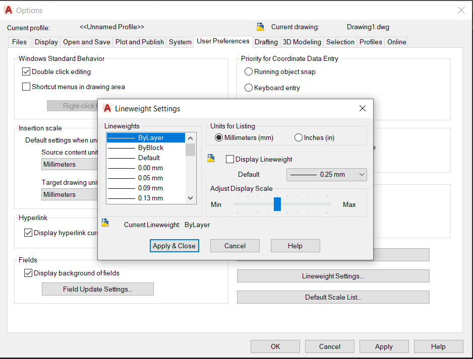
Lineweights are listed in millimeters by default. (This is because lineweights were originally designed for use with carousel pen plotters, and the width of plotter pens is generally measured in millimeters.) If you’re working in inches, this may make calculations difficult. However, you can change that default, using the LINEWEIGHT command. In the Lineweight Settings dialog box that opens, change the setting to inches.
If you turn off the display of lineweights (the LWT button on the status bar), you lose the thickness.
If you want all of your properties to be defined in your layers, you need to create a special layer for your circle.
On the other hand, this may be simple for you. Just draw a circle, select it, and enter the lineweight in the Properties palette (Ctrl+1).
## Dynamic block is another great productivity tip to master. Sign up below to get your Free tutorial on creating a complete dynamic block, including a drawing to practice on. You’ll make a movable chair, resizable desk, and more.
Trim the circle in half and use PEDIT
Jon e-mailed me with the following additional solution: If you use a circle and trim it in half, pedit that, you can then give the resulting pline arc thickness, mirror it and pedit join it into a circle.
I was also able to use the JOIN command to join the two circle halves.
Use the BOUNDARY command
Juan Cadavid wrote in another excellent way to create a circle with thickness, using the BOUNDARY command. Follow these steps:
Draw a circle
Type boundary on the command line
In the Boundary Creation dialog box, check that the Object Type is set to Polyline.
Click the Pick Points button and click inside the circle.
Press Enter to create a circle polyline.
Use the PEDIT command to change the width, as described previously.
Which method do you use? Or do you have another method? Leave a comment!
Let’s say that you add some text in your drawing, but then decide that the text should really be in a Notes box in your title block.
Or, you add some text in your title block and then think, “No, it should be part of the drawing.”
You can move objects from model space to paper space and vice versa, with the CHSPACE command. It’s quite simple:
Click a layout. You need to be on a layout tab to use the command.
Make sure that you’re in the space you need to be in to select the object you want to move.
If you want to move an object from paper space to model space, you need to be in paper space to select that object. If you aren’t in paper space, double-click outside the viewport to enter paper space.
If you want to move an object from model space to paper space, you need to be in model space to select that object. If you aren’t in model space, double-click inside the viewport to enter model space.
Go to Home tab > Modify panel (expanded)> Change Space to start the CHSPACE command.
At the prompt, select one or more objects to move.
Press Enter to end selection and the command. AutoCAD moves the selected objects to the other space.
Tip: You can select the objects before starting the command. Then the command moves them without further input from you. It’s very quick.
## Dynamic block is another great productivity tip to master. Sign up below to get your Free tutorial on creating a complete dynamic block, including a drawing to practice on. You’ll make a movable chair, resizable desk, and more.
On the command line, you’ll see to messages like these:
1 object(s) changed from PAPER space to MODEL space.
Objects were scaled by a factor of 1.31642071267405 to maintain visual appearance.
The command scales your objects! According to the Help listing for CHSPACE, the command scales the objects “appropriately.” I haven’t figured out exactly what this means and how the scale factor is calculated. If you know, please leave a comment!
Do you use this command? Why? I’m especially curious about why people might use it for objects other than text.
We often encounter objects and details that might be too complex to draw in 3D. From columns and balusters to spigots, escutcheons, machine parts etc.
But as like most things, complex objects also have humble beginnings.
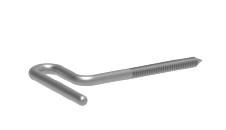
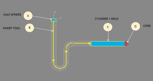
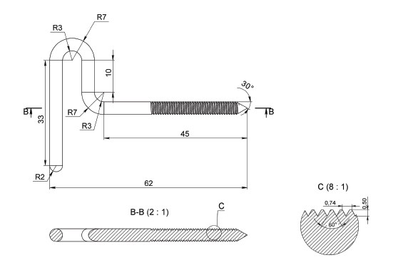
For this example, we can see that the object resembles a hook (see final image above), which we can segregate to several components, (A) spherical head, (B) cylindrical curved body, (C) threaded part, and (D) pointed end. From these parts, we can infer that it is composed of a half-sphere, a circle extruded in a direction, a spiraled rectangle, and a triangle.
After identifying these basic geometries, we can now start creating the 3d model based on this perimeter/dimension:
1. Open a new drawing. Make sure you are working with GRIDMODE (F7) and ORTHOMODE (F8) on. 2. First, we identify major dimensions for the solid (midpoint and boundaries), set the center point to 0,0. Switch to 3d Modelling Mode 3. Component A. From the center point, Use the command SPHERE, from the center point create a sphere. Enter the diameter or snap to reference lines. From the boundary lines, create a box. Extrude towards the apex of the sphere, snap. Type or click INTERSECT. You are now left with half of the sphere 4. Component B. From the base of the half-sphere, create a CIRCLE from the center point. Switch to side view and identify major dimensions in elevation (critical areas where parts of the solid merges, bends, or intersects). Using POLYLINE, draw the outline perpendicularly starting from the center. Using the SWEEP command, click the circle and follow the outline. Click or press ENTER. 5. Component C. To achieve the threaded part, we will circumscribe a CYLINDER (CYN) from the end part of Component B. Create a circle smaller than the previous component (Radius- Thread depth), use this as the diameter of your new cylinder, indicate the length then press Enter. After making a cylinder, we create a winded thread around the smaller cylinder. Using the HELIX command, indicate the base and number of turns based on the segments of the thread (Length-Thread Distance). Stretch towards the length of the model. Press Enter. 6. Component D. To create the conical point switch to the UCS as before, then click or type CONE. Indicate the cone base and height as prompted. Press Enter.
Finally, to weld together all the parts of the model together, select UNION. Select the different parts and then Enter. You now have a completed AutoCad 3D model of a hook.
Any questions about this tutorial? Do you have any tips to help make this tutorial easier? Did you find this tutorial helpful? Leave a comment! And please share the knowledge using the Share buttons below!
A script is a macro, a list of commands that you can run all at once, and as many times as necessary, allowing you to automate tasks that would take a long time if you did them manually. Using Scripts in Autocad can be very powerful and you can run them on objects in one drawing, or on many drawings. AutoCad Script function have been around for many years and many people have a library of many scripts that they use.
Here are 3 important points that you need to know about script in AutoCad:
Scripts are text-only (ASCII) files. You usually create them in Notepad.
They have an SCR filename extension, so be sure to save them that way.
Scripts use command-line syntax only. They can’t access dialog boxes, toolbar buttons, etc.
Scripts just execute commands. If you can’t do it by typing on the keyboard, you can’t do it in a script. The value of scripts is that you can use them over and over and they can do long lists of commands, even on many drawings.
If you require more automation beyond the functionality of Script in AutoCad , you may need AutoCad AutoLiSP function or other programming language. Check out our blog post comprehensive AutoLisp tutorial on How to create a custom command for AutoCad using AutoLISP.
Follow these steps to create a script file:
Set the FILEDIA system variable to 0, to stop dialog boxes that access files from opening.
Run through the steps that you want to automate, using the command line only. Write down (or type in Notepad) the steps. You can copy your command line entry directly to Notepad. Press F2 to open the AutoCAD Text Window for that purpose.
Press Enter at the end of each command or use a blank space, which is the equivalent of pressing Enter. The script reads every space, so you need to get it exactly right! The script is easier to read if you put each command on its own line.
Enclose layer names or files names (and file paths) that contain spaces in quotation marks.
Insert comments periodically for explanation. To insert a comment, precede the text with a semicolon.
Save the file with an SCR filename extension, by typing .scr after the file name.
Set FILEDIA back to 1.
To run and test the script file from within a drawing, use the SCRIPT command. A dialog box opens, where you can choose your script file. Click Open and the script runs.
Let’s say that you want to run a script file on more than one drawing. You can use the OPEN, CLOSE, and QSAVE commands to open drawings, run some commands, save the drawings, and then close them. You can still start the script from within the 1st drawing, but you can also start a script file as you open AutoCAD.
To do so, you change the expression that Windows uses to open AutoCAD. The best way to do this is to use the shortcut on your Desktop. Follow these steps:
Right-click the shortcut and choose Properties.
Click the Shortcut tab.
At the end of the existing expression (which reads something like C:\Program Files\AutoCAD 2009\acad.exe) add a space and then the following: /b script_name
Click OK.
Double-click the shortcut to open AutoCAD and run the script.
For those interested to explore Automation in AutoCad further, you will find more comprehensive AutoCad Lisp commands, AutoLISP tutorials & examples in my book, Top Customization Tips Every AutoCad Users Should Know.
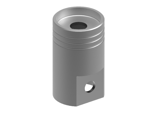
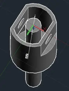
In this tutorial, you will learn how to create a piston using 3D geometry in AutoCAD. You will be guided to use 2D drafting commands, annotations as well as some 3D features (EXTRUDE, REVOLVE, SUBSTRACT, CHAMFEREDGE, FILLETEDGE, TORUS).
The final model should look something like this image in 3D.
He created this exercise series to help others speed up their learning process and make it more hands-on and fun. If you want more exercises like this, you can get them here.
Note that the exercises are 2D and 3D drawings without instructions so that they are not specific to AutoCAD. You can practice using other program if preferred.
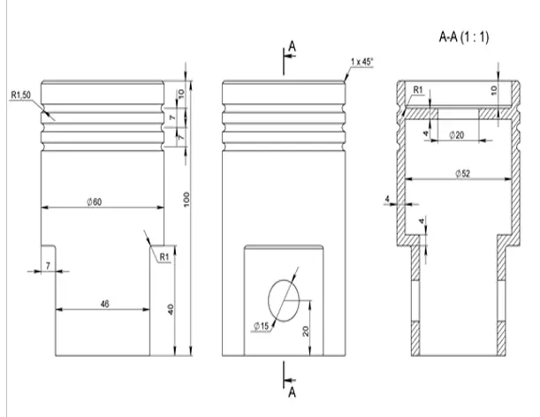
The piston 2D perimeter is below. The dimensions shown below are originally metric. However, for the purpose of this exercise (as because it is all proportional anyway), you can use the same values with imperial units if relevant.
You can also download the finished Piston 3D model here.
Tips from the author: Explore gridmode (F9) and snapmode (F7) to help navigate between drawing tasks.
Let’s get started.
Draw a circle with a diameter of 60 and place its center on the origin (0,0).
Draw a 23 length horizontal reference line from the origin.
Draw a rectangle from the end of the reference line. The exact size is not critical as long as it is larger than the circle.
Then mirror the rectangle using the (0,0) for mirror line. Delete the reference line.
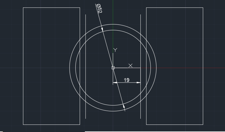
Offset the circle. Set offset distance to 4. You will get a smaller circle with diameter of 52.
Draw a vertical line at the centre of the circle (longer than the circle itself). Offset by 19 units both to the left & right of the centre line. Then delete the centre line.
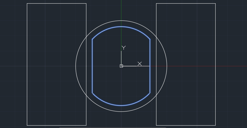
Use TRIM command and the 2 vertical lines as edges to trim the inner circle.
Repeat TRIM command, this time choose the arc as edges to trim the excess vertical line.
Then use the JOIN command to make the following shape in the center.
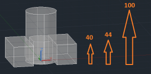
Switch to 3D viewpoint (Isonometric) for the next steps for easy viewing.
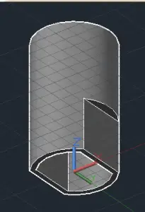
Use EXTRUDE command to make the 2D shapes created in the previous steps to a 3D model. Move cursor to the Z direction and type in 40 units the 2 x rectangles, 44 units for the “rounded rectangular” in the middle and 100 units for the circle. Choose x-ray visual style to see the wireframe & shading as shown below.
Then using SUBTRACT command to cut out the 2 x rectangular and rounded rectangular shapes from the main cylinder. (Select the main cylinder first, enter, then select the objects to be subtracted). Note: You may need to change your viewpoint or visual style in order to select and subtract the central shape. You should now have a model similar to the one above.
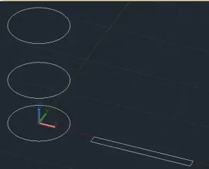
Next, we are creating more 2D shapes. To make it easier, draw these outside of the main 3D cylinder. Draw a 52 unit diameter circle and a rectangle (7.5 unit high by 100 unit long). Create 2 more circle using COPY command. Move cursor in the z-direction, 44 units for the 1st circle and 100 units for the 2nd copy. Delete the base circle.
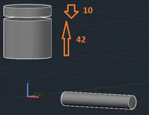
EXTRUDE the 2 circles to create “vertical cylinder”; the lower circle should be 42 units upwards and the circle on top should be 10 units downwards.
Use the REVOLVE command for the rectangle to transform it into a “horizontal cylinder”. [Revolve – Enter – Select the rectangular, Enter, Select the axis start and end point (the long edge) – Then use the default 360° revolution]
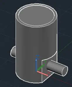
Use the MOVE command and select the 2 x newly created “vertical cylinder”. Select centre of top cylinder face as the base point and move and snap to the centre of the main cylinder top face.
Now we need to move the “horizontal cylinder” to the position shown in the image below. First, align the bottom node of the cylinder to the midpoint of the flat pane. Then move 20 units in the z direction and move towards the piston body in x direction so that so that it extends on both sides.
Now SUBTRACT the 2 x inserted cylinders from the main body. You can use the Bottom view for easier access.
Then create a 20 unit diameter circle and extrude it so it extends beyond the main cylinder. Then SUBTRACT to create a hole on the top face.
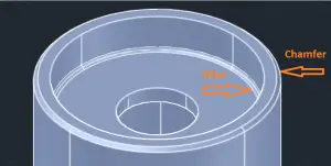
Next, we will use the CHAMFEREDGE command for the outer edge of the top face of the cylinder. Type “d” to choose distance from the edge. Type 1 unit as the distance and then press Enter and repeat the distance -1 and enter to finish.
For the inner edge of the top face of cylinder, use FILLETEDGE command as shown in the image below. Type “r” to select the radius. Choose 1 unit as the radius and press Enter.
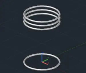
The final component to the piston is the ring grooves on the outer wall. To create this, we will use the TORUS command. Set the center of to the origin (0,0) and then select diameter (d) and type 60 units and then type 3 units as the thickness or radius. Make another 3 x ring duplicates (using the COPY command) with the following values in the z-direction: 76, 83 and 90 units. Then delete the original torus. You may want to use isolate (hide) the main body for this step.
Finally, subtract the 3 torus from the main piston and voila, your 3D piston is completed. You should now have a final model similar to the one at top of the page.
Any questions about this tutorial? Do you have any tips to help make this tutorial easier? Did you find this tutorial helpful? Leave a comment! And please share the knowledge using the Share buttons below!
With the rise of the current global pandemic, our way of life has been changed in an instant. Gone are the days where we can comfortably walk down the streets to work, enter busy cafes to dine, and travel without having a little tinge of worry. The coronavirus has sent us packing our things, heading home, and observing social distancing -all to avoid contracting this disease. This made our companies either send their workers to work from home or worst, close and lay-off its employees.
One of the challenges of the current pandemic is meeting the large demand for medical equipment and protective gear. With high demand and low supply for PPEs, we are struggling to secure enough gear for our hospitals and social institutions. And this applies to most of us as well, since going out without protection meant we are actively or unknowingly contributing to the spread of the virus.
But where can we help? People around the world have been using this quarantine period to dedicate their time to creative projects. Some have been crafting masks while others are creating face shields and equipment. For some enthusiasts, they accomplish these by utilizing 3D printing. It is also seeming to be the right and timely idea in helping our manufacturing and import sectors to cover the gap in the supply chain. By utilizing this technology, we can independently fabricate face shields, mask holders, and makeshift ventilators right from the comfort of our own homes. As templates can be easily sent online, it can offer an efficient and local solution globally.
Here are some ideas that you can accomplish with 3D Printing:
Face Shields and Masks. Face shields are technically headbands or sun visors with clear plastic at the front and sides of the face, completely covering both sides. Here is a good face shields template
Mask Accessories. Ear savers and clips are accessories that helps to fit the masks comfortably. It also eases the pressure off by pulling the elastics when you wear it all day long. See more mask accessories template here
Makeshift Ventilators. Ventilators help patients breathe easily by pumping oxygen into the lung via intubation. By creating a splitter for a single machine, it can serve two patients instead of one. Some are also able to create fully functioning ventilators by 3D Printing parts. Find makeshift ventilator details here.
Toys. As we are confined to our homes, mental health is also an important aspect of your life that you want to focus on as well. From little toys for kids to grown-up frisbees, there is a lot of templates you can choose from to create a fun activity while in isolation. Here are some exciting 3D printing projects for you and your family
Typically used for architecture and engineering prototyping, additive manufacturing, or 3D printing, as we know it today, has been in development since the 1980s. With renewed interest in the previous years, architects, engineers, and hobbyists have been tinkering with objects and possibilities with this machine. A typical 3D maker machine produces an object by successively laying down thin layers of material atop each other.
The process usually starts from preparing a 3D object, which can be done through a Computer-Aided Design (CAD) program. From there, you can study the model and look for ways on how it can be printed efficiently.
Here’s a step-by-step guide to help you develop your CAD file for 3D printing:
1. First, you can load an available 3D file or create from scratch 2. Select, “File” click “Open” from the window, select the file you want to use or to start a new file press, “New” then click “Drawing” 3. Select “PLINE” then draw or trace the outline of the model you wish to create Make sure you have a closed polygon. Right-click, then select “Close” 4. Select “3D Modelling” workspace in the general window ribbon. Notice that your tools ribbon has changed to modeling tools. Click the square in the far right corner to switch to an isometric view. Your model is now in isometric 5. To add depth to your model, select or type “Extrude”. Select your Model. You may navigate the UCS and see values change as you pull towards the direction of extrusion. 6. Enter your desired value or height of the object. Press, “Enter”. To learn more about making 3d models in CAD, click here. 7. Switch to “Realistic” from the view tab to view it as a solid 8. From the “Home” ribbon, you may check “Smooth Object” to round out edges 9. From the “Output” tab, select “Send to 3D Print Service” 10. A Window will pop up prompting you if you want to continue. Click Continue 11. Once you’ve ensured dimensions are correct, save as a stereolithography file or “.stl” file
Now you are ready to print your model, all you must do is to wait for the final product to be produced. The amount of time for printing an object depends on the materials to be used and the complexity of the project. Most projects as simple as this may take a few hours or less in production, enabling you to make more of it in a day.
Aside from standard plastic and PLA (nylon), you may also use resins, polyurethane, and metal, filaments to print your material. This enables you to explore a variety of options and experiment scale and materiality on different projects. Aside from PPE’s you may experiment with these materials to create functional objects made from metal or reusable items from polyurethane.
With the uncertainties we are facing right now, it is a good thing to know that we can utilize our skills and our hobbies towards something that can benefit all.
Some of you might say this blog is common sense or such a simple one. But hey, sometimes all the simple ones are being forgotten.
By the way, my name is Johan. I am a licensed Architect and user of Autocad for years. I would like to share with all of you some tips that I find really useful in setting up your AutoCAD software after installation. Why? So when you start doing your projects, it will be easier as your standards are already made. It will also be less time consuming because you don’t have to set it up every time you have a new project. You just have to make a copy and rename them.
Settings
(by the way, in my displays below, I am using Autocad 2018, most of the time, in lower versions, commands are under the same tab/menu/toolbar)
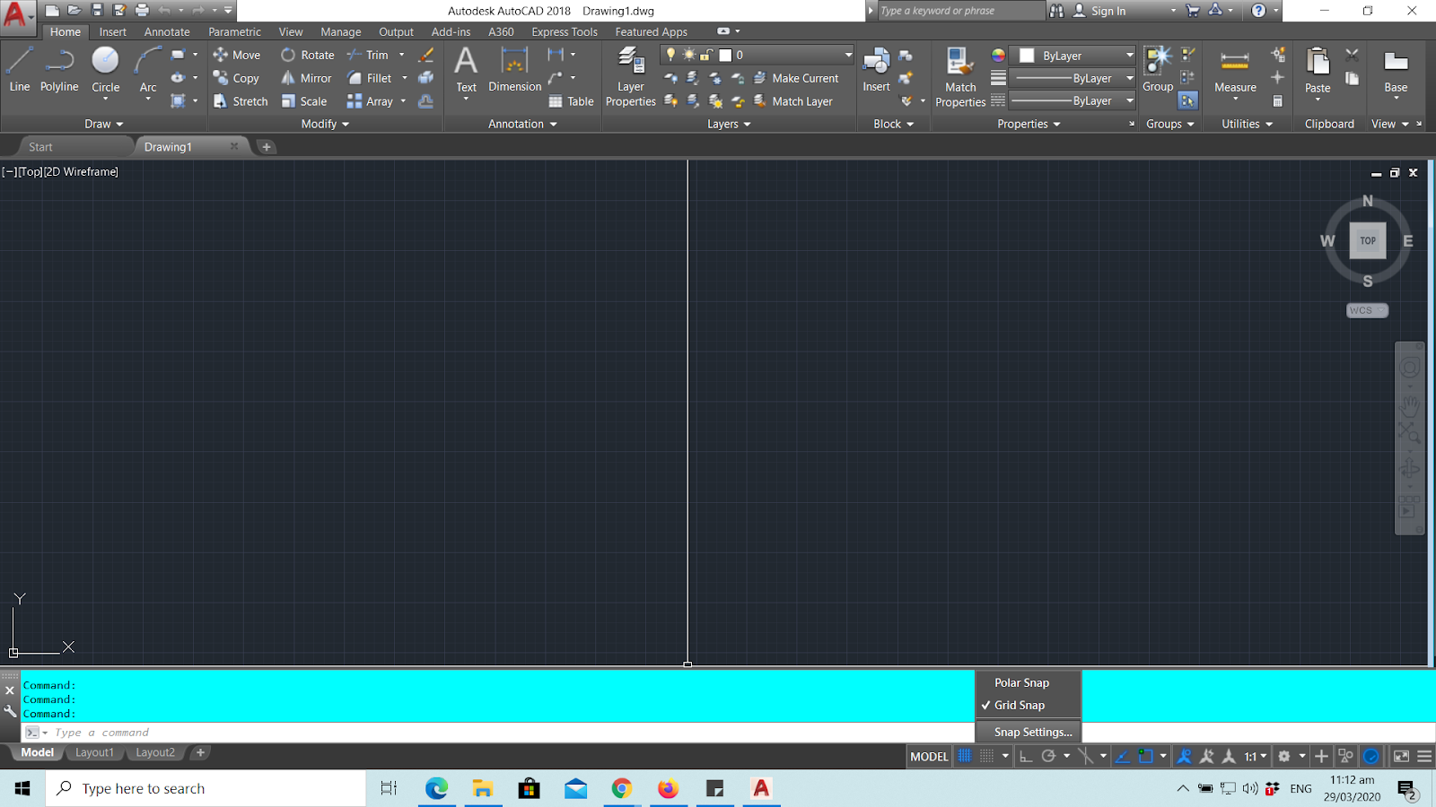
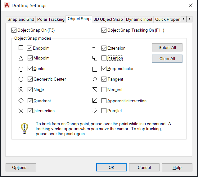
> Go to Snap settings from Status bar
> Go to Object Snap, it is preferred that you check all except for Insertion, nearest, apparent intersection, and parallel. This will make your life in the future easier and you seldom used them anyway.
> Then go straight to “Options” without hitting “Ok”
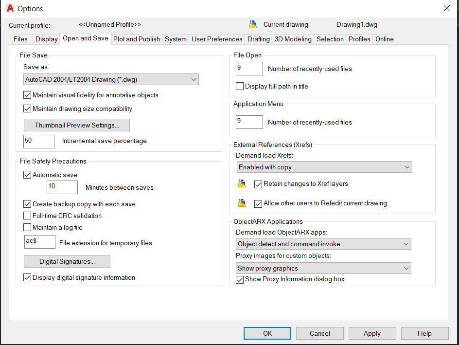
> Click “Open and Save”
I advise that you always have your AutoCad be saved in other versions so just in case you are sharing it with others who don’t have the same version as yours, they can still open it.
Also make sure that the box for “Automatic Save” is checked, then you can customize the time either 5, 10, 15 minutes, or so… This is to make sure all of your work is saved in case an internal error occurs. But I would say, 15 minutes is fine.
Just leave the rest as is – on default.
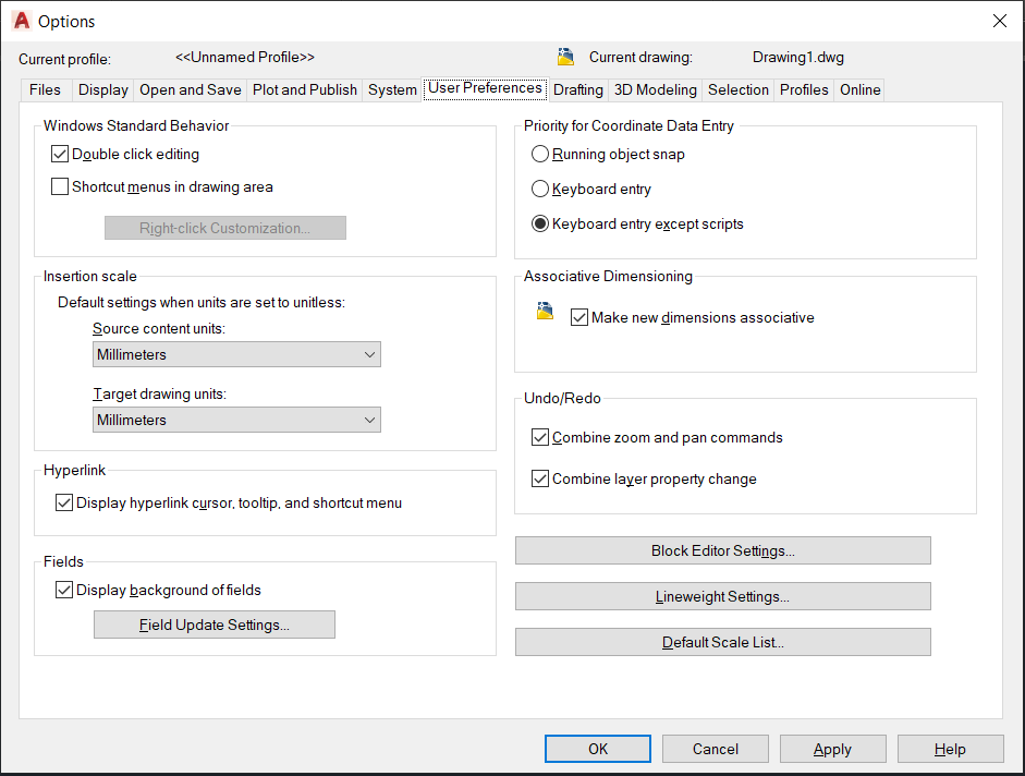
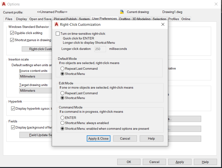
> Jump to “User Preferences”. Click on the “Right-click customization”. Tick all “Repeat Last Command” and “Enter” then apply and close.
This is quicker in repeating the last command you typed in by hitting the right click of your mouse.
> As for Insertion scale, you can change it depending on the unit of standards in your country, either Metric – meters/millimeters or English – feet/inches.
> Also under this tab, it is always better to have your Line weight Settings in “By Layer”.
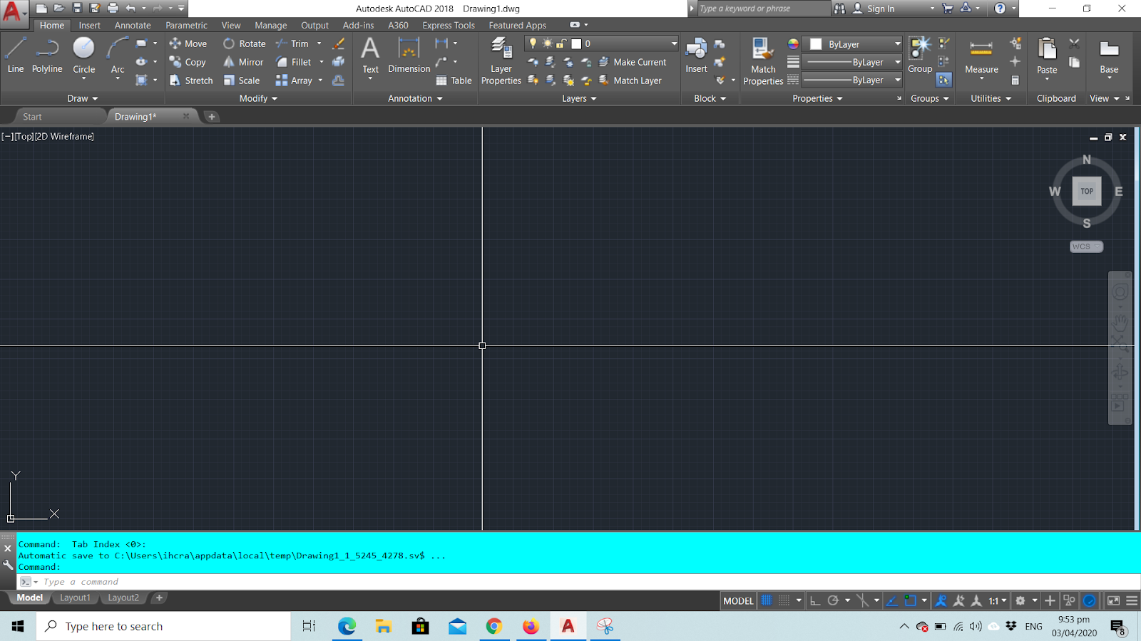
Additional Tip: You might want to extend your crosshair like this
That way, it’ll be easier to see things aligned if you are pasting different figures here. Just go to “Display” tab and adjust the Crosshair size to 100.
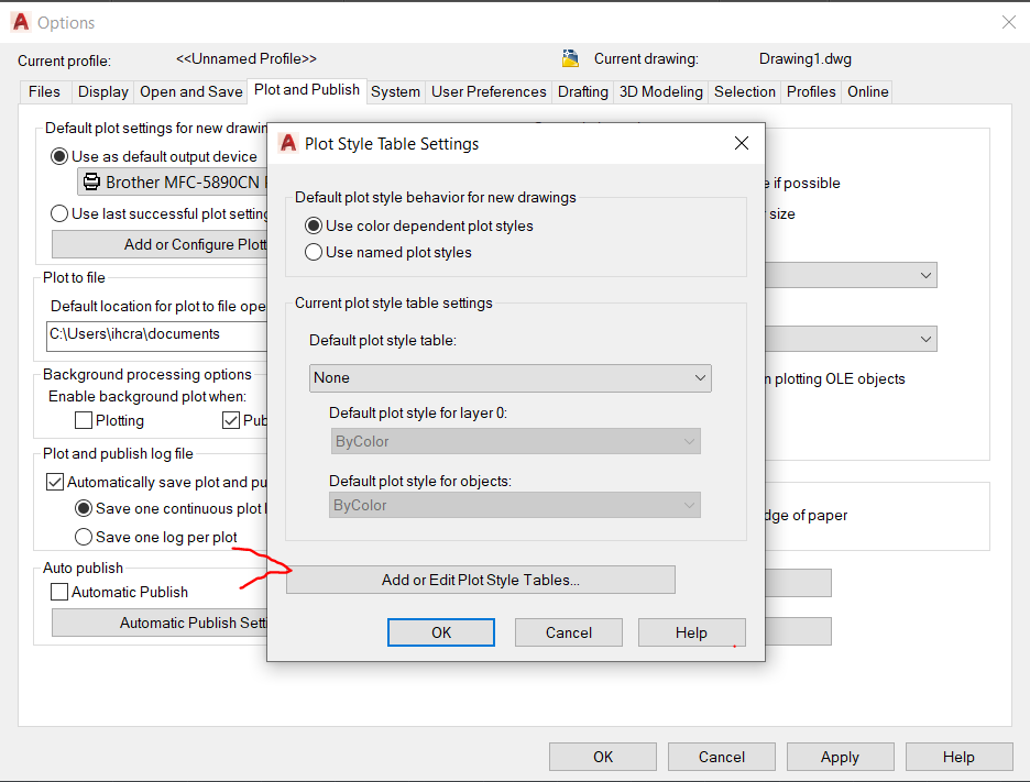
2. Customizing CTB
Now, there are 2 ways of getting here. A. is through “Plot and Publish” tab, then click “Plot Style Table Settings” then “Add or Edit Plot Style Tables”
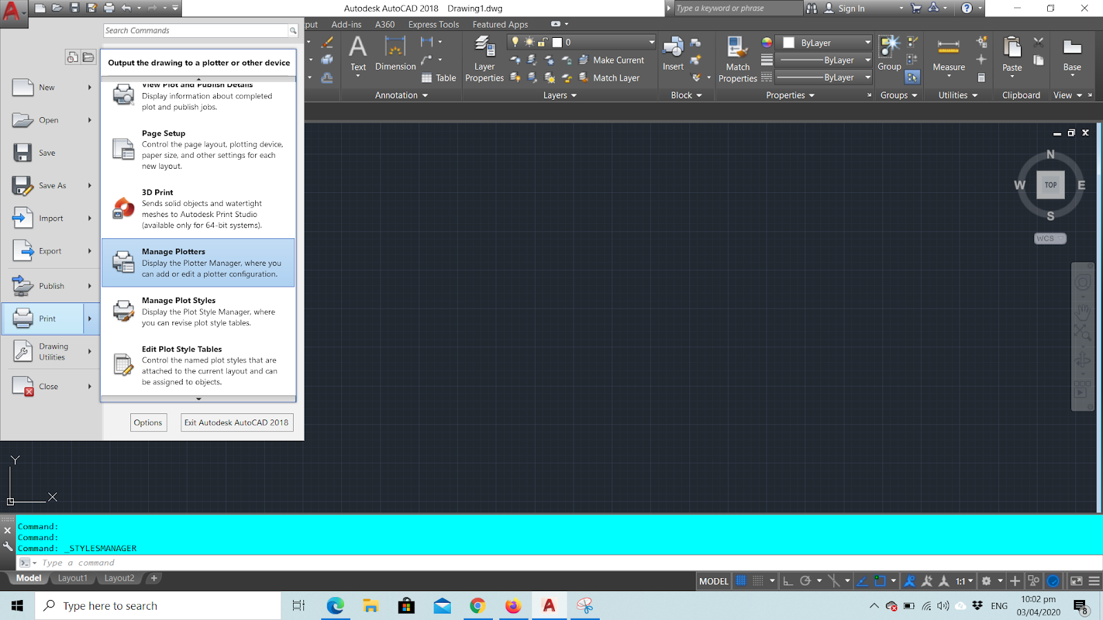
Or B. through the File menu > Print > Manage Plotters
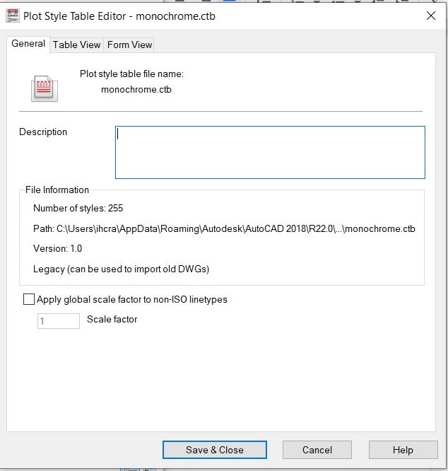
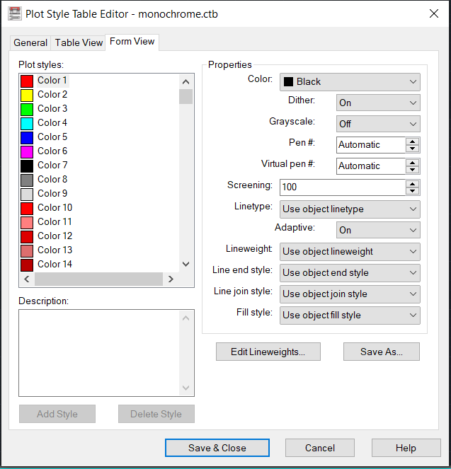
Copy any of the CTB here with label under Type as Autocad-color dependent plot style table file, and it will open like this
Put the color on black as default, then you can assign your Lineweights per color. From the thinnest pen to the thickest one. And then hit “Save as” and create a name for that CTB you just made so you still have this default one that you opened. And it is advised that you save it at the same location of the folder where all CTBs are. So when you plot, it will reflect once you print for you selection of CTB.
3. Setting your layers
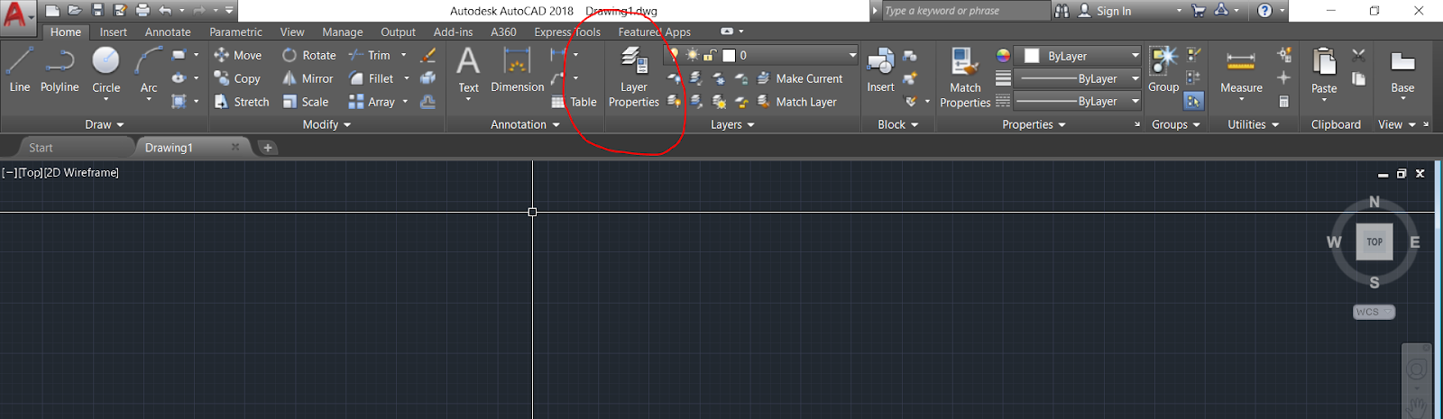
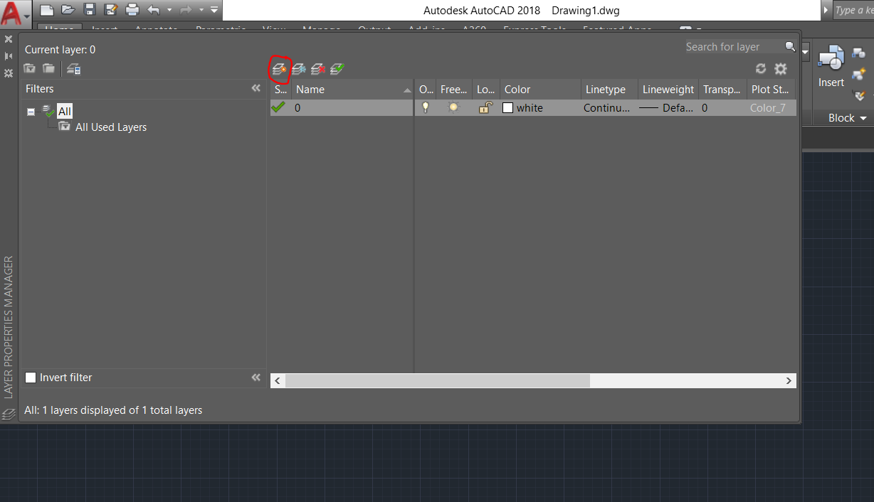
> Go to “Layer Properties”
Click on the first icon in the center to create your first layer
Just go ahead
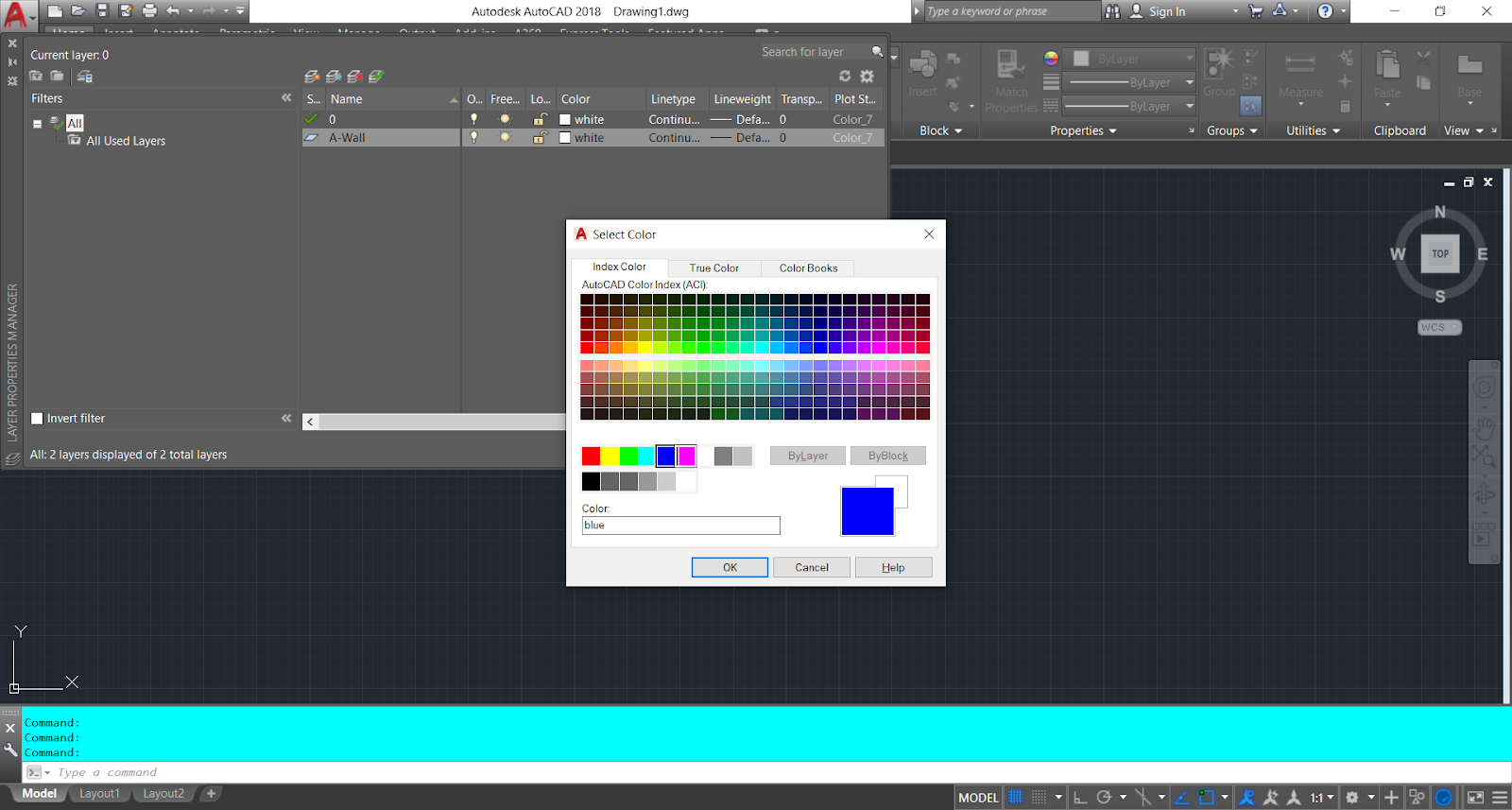
Just go ahead and make your layer and color pen assignments.
Assign the colors according to the CTB you made that also corresponds to your Line Weights.
And repeat the same steps to add more layers.
This is it for now for. We’ll continue on our next blog for another tip. Till the next. If you have any questions, feel free to message here.
One
of the tools we often use by technical professionals such as architects and
engineers is the computer-aided design (CAD) program. Nowadays, it is one of
the crucial tools in delivering contract documents for construction and other
technical businesses. It is initially meant to aid us in realizing projects by
producing drawings that are portable, easy to revise, and coordinate among
different trades.
Throughout
the years, the CAD system in place also adapt to the changing technology, from
what used to be ordinary drawings and linework, it can now handle
three-dimensionality and create rendered pictures as well. Such flexibility and
evolution allow CAD to remain as a staple tool for designers and architects
such as myself.
As
it is something that is meant to aid our manual drafting systems, it is not to
say that it doesn’t have any flaws. As younger generations of architects took
up skills for CAD, earlier generations of architects might be unable to allot
time to learn such new developments. What used to be their guidelines on paper
became XLINE in CAD, stacks of tracing papers to LAYERS toolbar, while copy and
array will be painstakingly transferred manually before, now it can be accomplished
by clicking a button or typing a command; and so, the list goes on.
Take
for example, those huge drawing we used to transfer to trace or use it as
reference now becomes an XREF or BLOCK in CAD. While if we needed just a
portion or make an item appear on top, we need not to trim the drawing piece by
piece but instead use tools such as XCLIP and WIPEOUT.
XCLIP is like cutting a paper to
patch an area in the drawing, or a Microsoft Windows snipping tool where you
can just capture a portion. It is a useful tool that allows you to snip what
you like without exploding the XREF or file that you referred to. This allows
for a lighter file since there is no need to explode a component or to go
through components to hide certain layers just to edit a part of the block.
I
find using XCLIP useful especially when there are areas in my XREF that I
wanted to use only as a reference. To navigate the XCLIP tool, here’s an
example:
Prepare the drawing to be referenced:
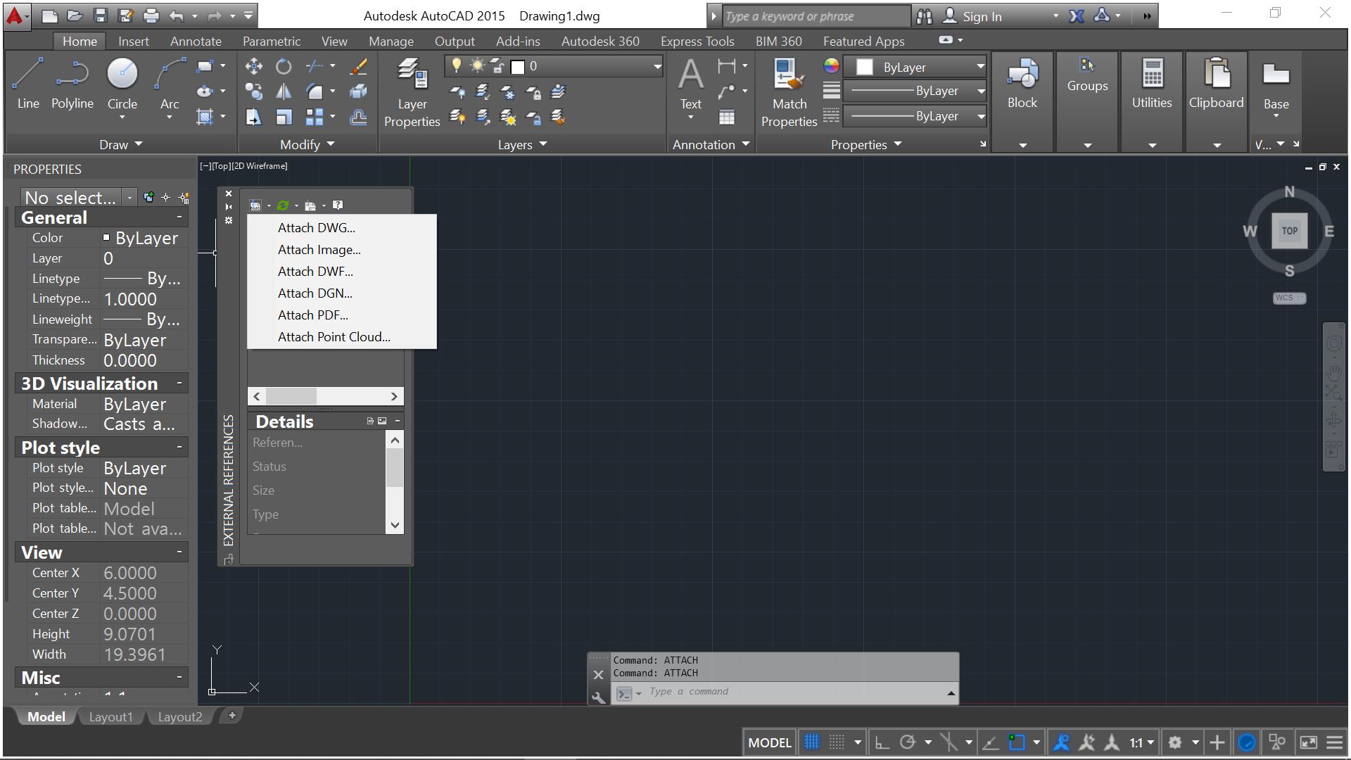
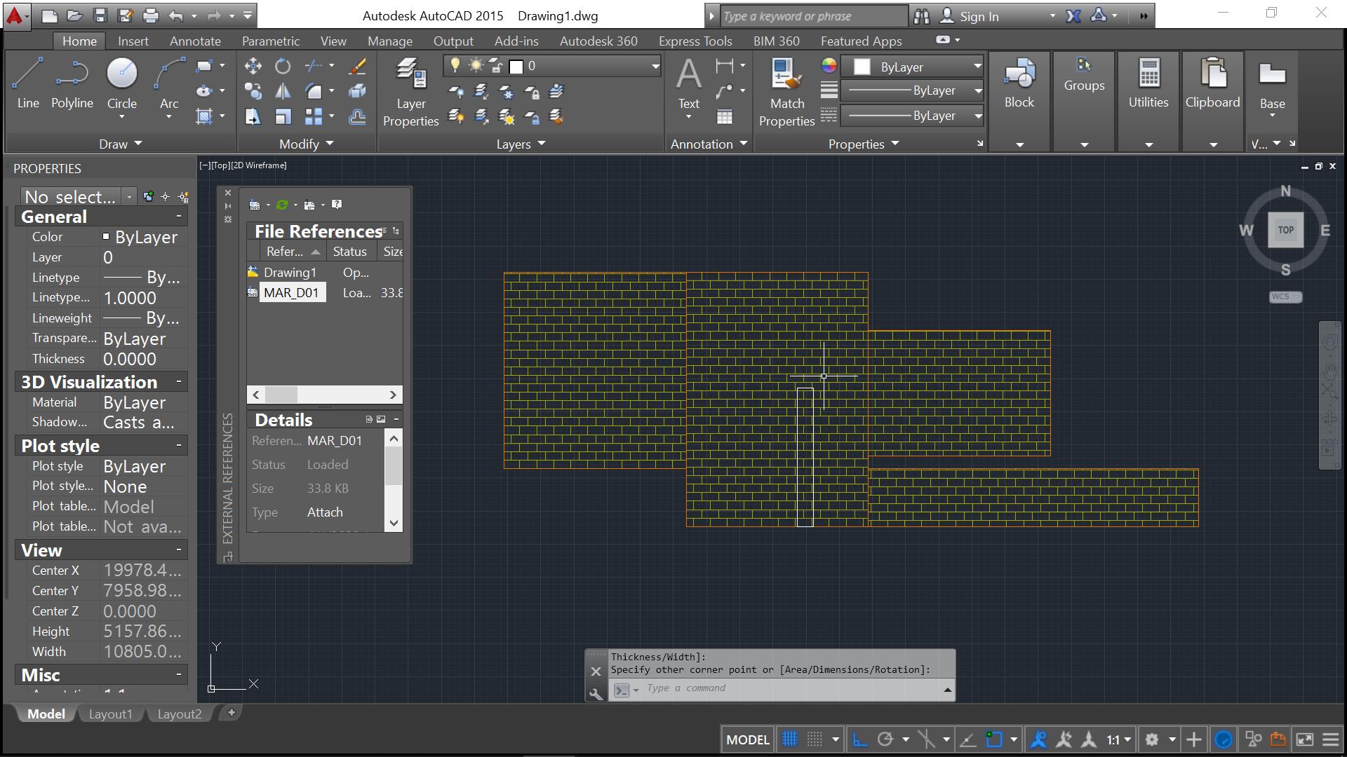
First, identify the CAD file you wanted to load into your file (Here we selected file MAR_D01.dwg which contains the file we want to reference). To load the file to your drawing, type XREF into the command line, press ENTER.
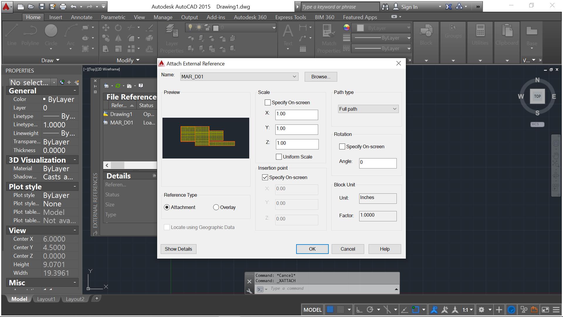
Once the dialog box is up, Type ATTACH in the command line or select the DWG icon in the toolbar (A drop down list is available to select the type of file you want to load – AutoCAD files, Image or PDF). Once a pop up window comes up, select the drawing you want to load, select OPEN. For more information on how to overlay or fully attach your XRef file, click here.
Once loaded and placed inside the drawing, you can now decide which part to use the XCLIP on. You can now navigate the XCLIP Command
Navigating the XCLIP tool:
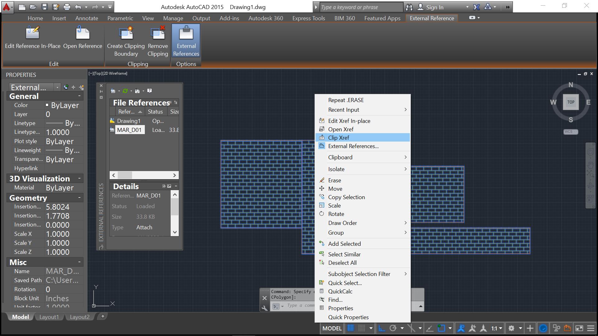
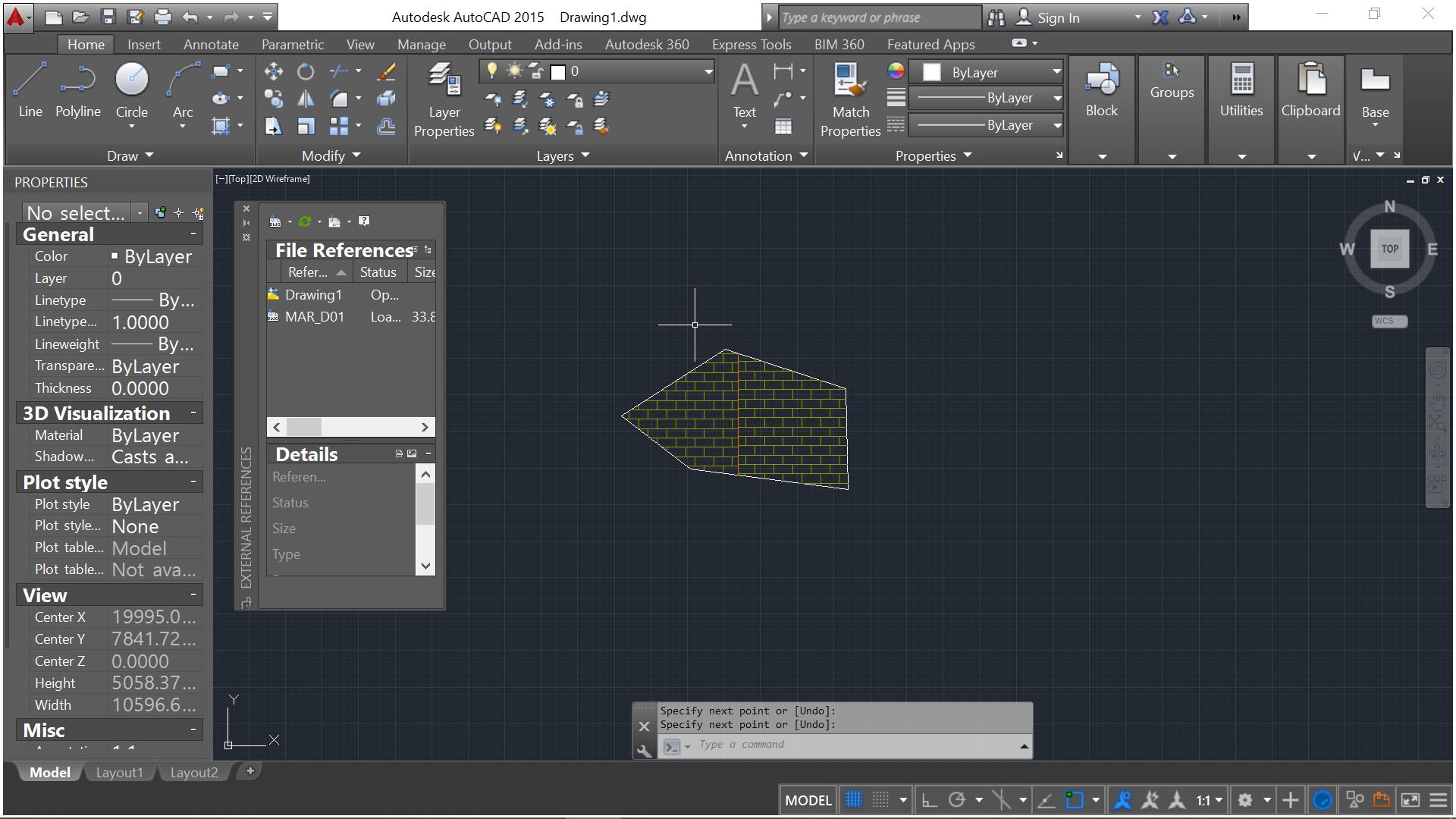
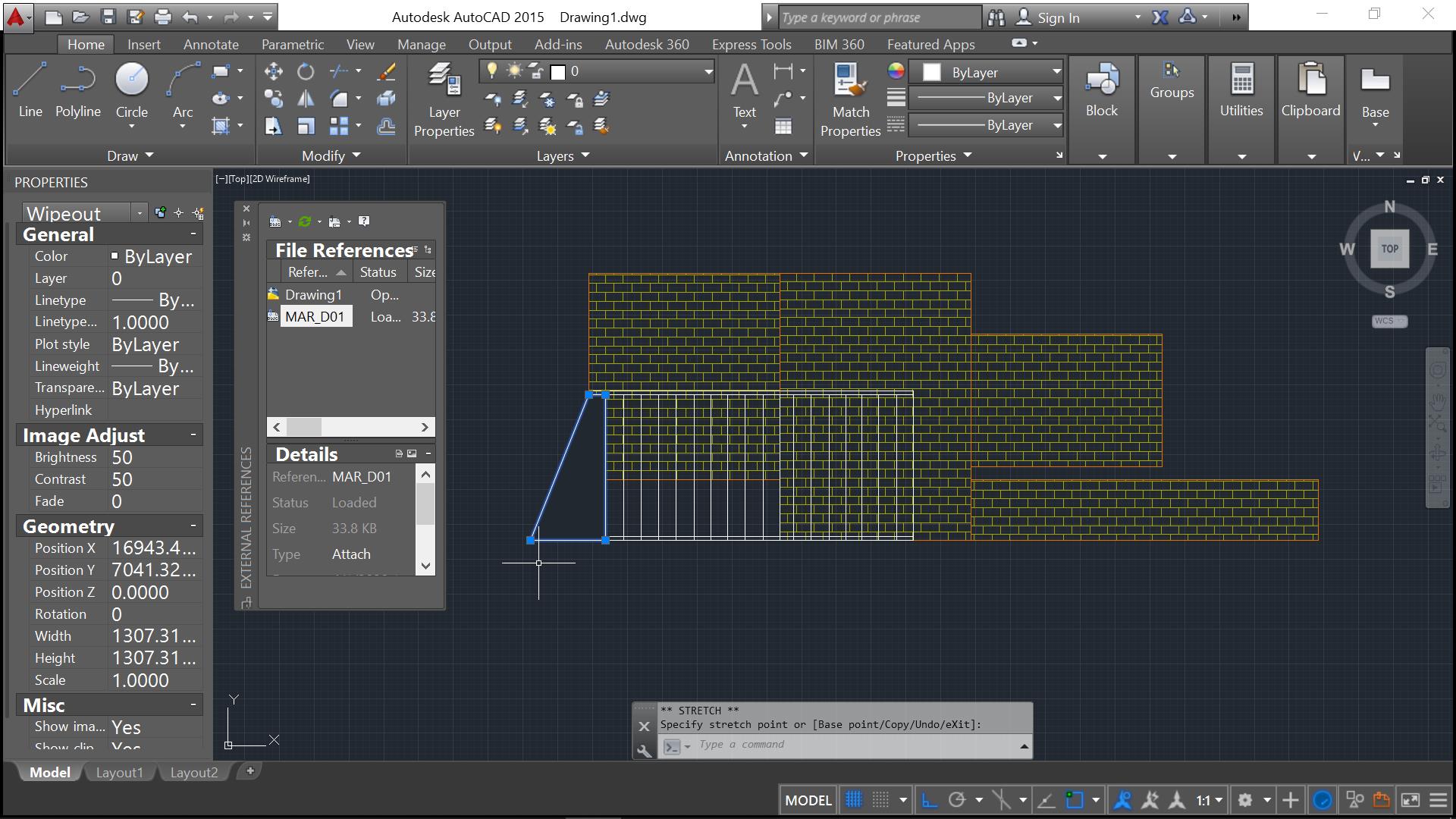
To navigate the XCLIP frame, type into the command box XCLIP, press enter. It will prompt you to select the item we want to clip. Alternatively, you can right-click in the drawing and choose CLIP XREF
Click on the XREF on the sheet (MAR_D01.dwg)
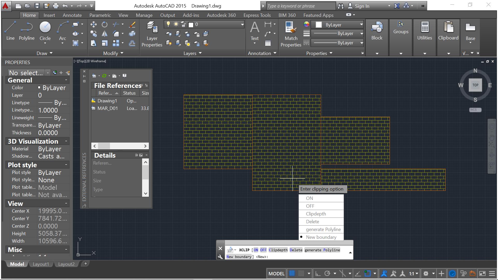
Clipping options will appear and request for your desired action. ON, OFF, Clipdepth, Delete, generate Polyline or New boundary. Select New boundary or type N
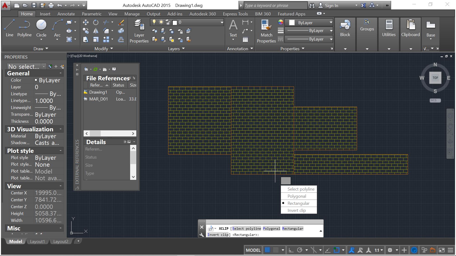
Next, select your bounding box for the XREF: Select Polyline (select and existing polyline, if you have a desired shape prepared), Polygonal, Rectangular or Invert Clip. Here I chose Polygonal
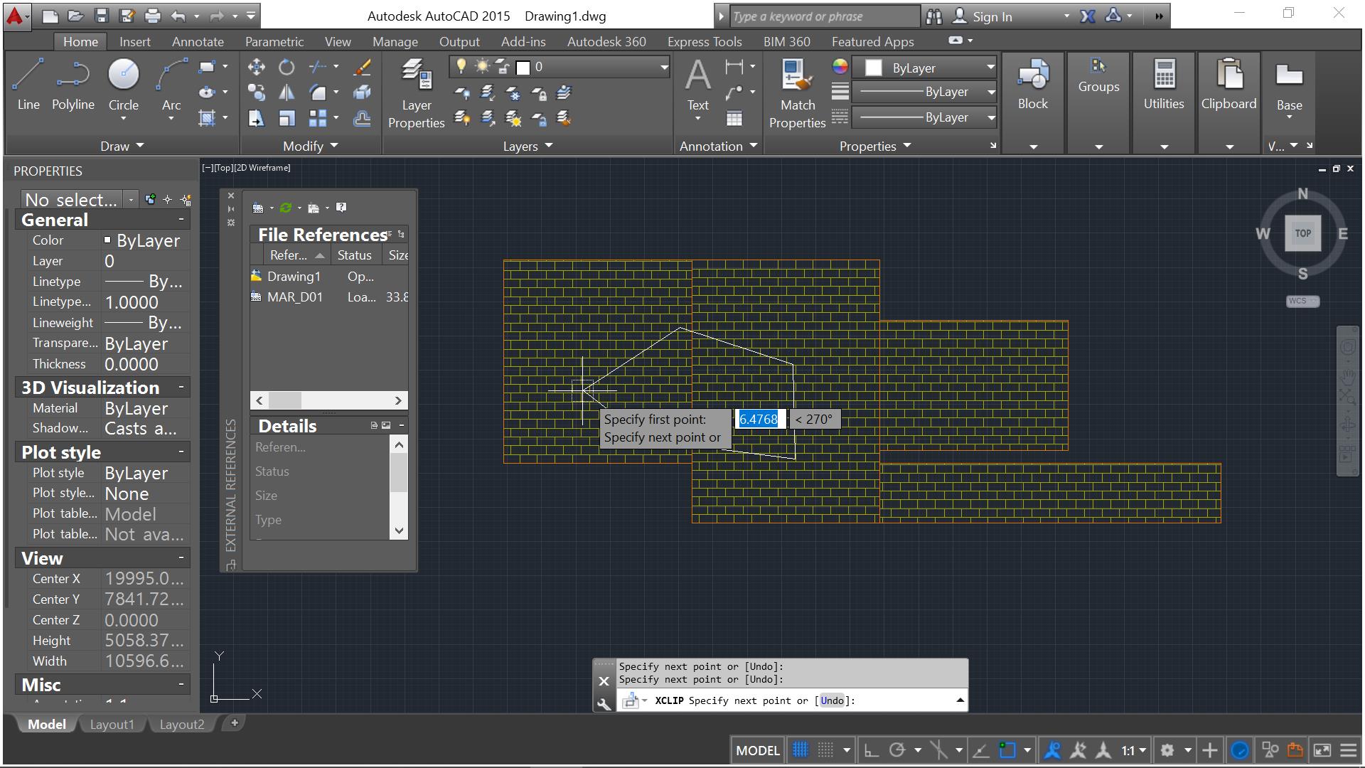
Specify points to your desired shape or outline, here you have a variety of sides and option as how you want to clip the drawing. Press Enter.
Voila, you have achieved to contain your XREF to your desired shape or outline. ———————————————————————————————
To delete the boundary and fit it in a different shape, you can repeat Steps 4 to 6 and choose OFF or DELETE.
My
next tool of choice is WIPEOUT. Despite
what the name suggests, it would not wipe out your drawing but rather it is an
effective tool in masking shapes that would otherwise be manually trimmed in an
exploded component. With this tool, I
can afford to retain design elements that is otherwise arduous to edit and
revise sooner or later. Take for example creating screen behind brick walls.
Instead of exploding the file (which is messy), we can opt to a cleaner and
easier means of wiping the shuttered areas out while not having to deal with
all the editing clutter and revisions:
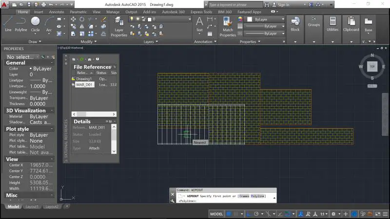
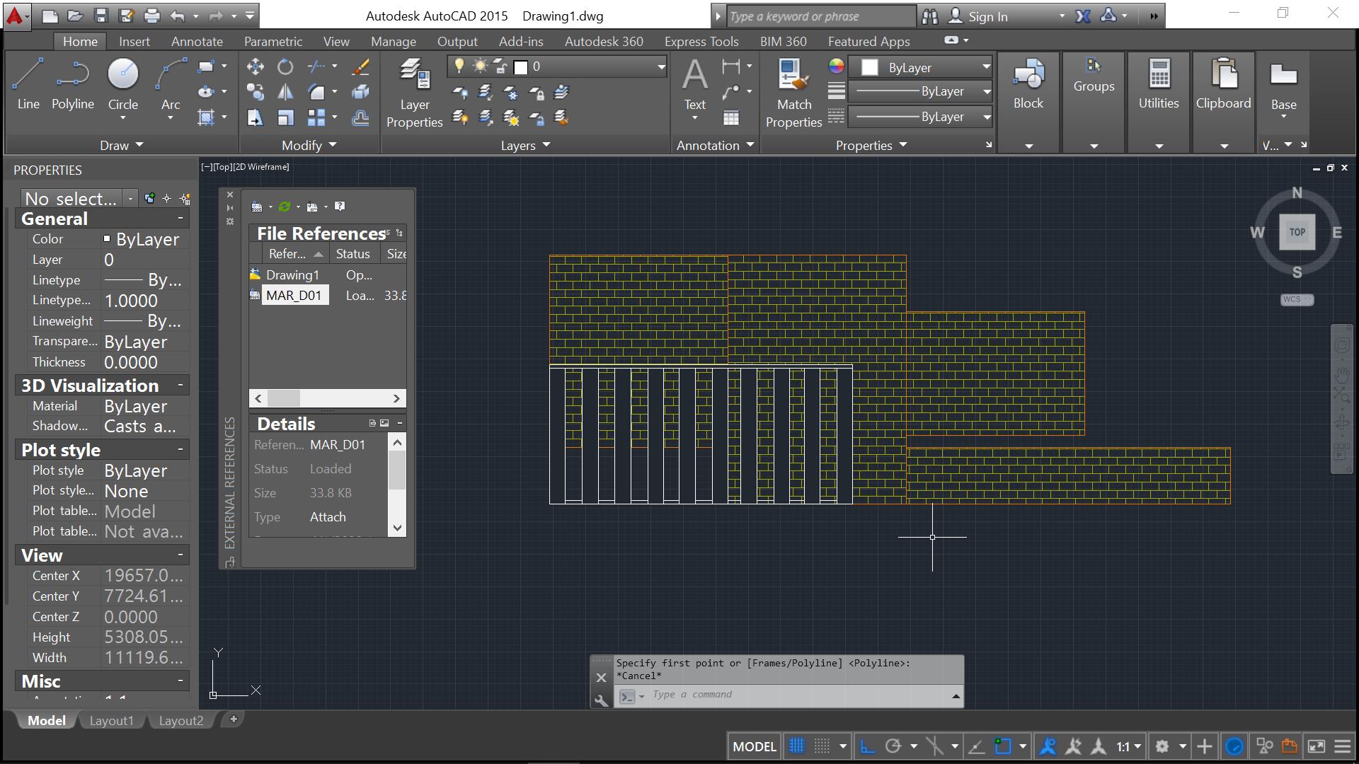
Working from our previous file, we can add elements in front of the brick wall by using wipeout. First, prepare by identifying the areas to mask (here we used rectangles). Type in the command line, WIPEOUT
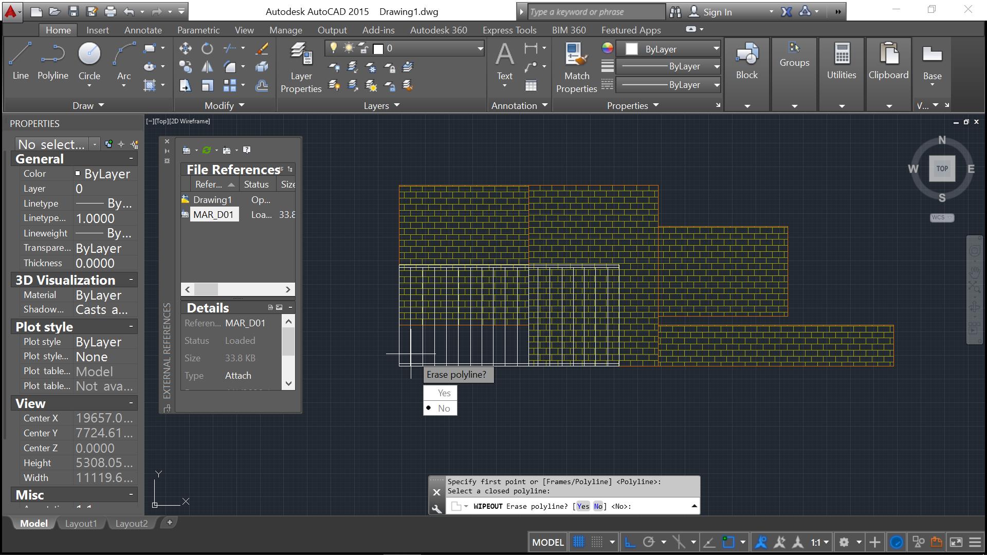
The command line will prompt you to select or outline the frames or polylines. Here we have selected Polyline. Proceed to click on the rectangle we made earlier.
Upon selecting the polyline, it will ask you whether to delete or keep the polyline. Click your preferred step. Here, we chose to delete it.
You can see that the polyline has been converted to a solid entity with control points that will allow you to manipulate the wipeout a bit further.
Multiply or modify the wipeout and we arrive to our initial intention of creating an easy shuttered brick wall. ————————————————–
For more thorough discussion about the wipeout command, check our previous posts here.
Hope these 2 simple tools can help you in creating drawings that are easy to access, share and edit. If you have any question in relation to clip and wipe out tools or any other Autocad drawing management tools, please feel free to post your questions in the comment section below.
AutoCAD can export to STL format which is what some 3D printers use.
Choose File (the Application button), Export, Other Formats and choose Lithography (*.stl) from the Files of Type drp-down list. Then select the objects that you want to include. There’s also an option Application button, Publish, Send to 3D Print Service.
from http://www.3dartistonline.com/news/2011/12/how-to-make-a-model-for-3d-printing/
With a 3D printer, we can create objects impossible to make as a single piece by other means of production. It is possible to print objects within objects, hollow parts, interconnected parts, moving pieces, complex twists, and intricate details.
There are numerous 3D printing technologies out there; stereolithography (SLA), selective laser sintering (SLS) and fuse depositing modelling (FDM) to name but a few, and each has pros and cons.
When you are considering preparing a piece for 3D printing – in this example, we’ll be producing an object in ceramics – we must first consider the design constraints before we select the 3D printing process.
In the case of ceramics, the minimum wall thickness possible is 3mm; the maximum detail is 2mm. In other processes, such as SLS, the minimum wall thickness might be as thin as 0.7mm and the minimum detail as sharp as 0.2mm, so it’s very important to know the process.
Something else to consider is cost – 3D printing is not necessarily a cheap process, so try to use as little material as possible.
Step 1 – Modelling
You can pretty much 3D print everything from organic ZBrush sculptures, mathematically complex models and sleek product designs, to your computer game avatar. Whatever you’re designing, keep in mind the real world. Your 3D model will become an actual object, so you must consider dimensions, strength and gravity.
So, for example, if you want to 3D print a figurine, make sure it will stand on its own two (or however many) feet, or consider adding a base.
from http://www.3ders.org/3d-printing-basics.html#3d-software-for-beginners
If you’re just getting started you can try some of 3D modeling software which can be downloaded for free.
SketchUp – SketchUp is fun and free, and is known for being easy to use. To build models in SketchUp, you draw edges and faces using a few simple tools that you can learn in a short time. With with Push/Pull tool you can extrude any flat surface into a 3D form.
3Dtin – The simplest 3D software. You can draw directly from your browser.
Blender – Blender is the free open source 3D content creation suite, available for all major operating systems under the GNU General Public License. Blender was developed as an in-house application by the Dutch animation studio NeoGeo and Not a Number Technologies (NaN). It is a powerful program contains features that are characteristic of high-end 3D software.
OpenSCAD – OpenSCAD is a software for creating solid 3D CAD objects. It is free software and available for Linux/UNIX, MS Windows and Mac OS X. it does not focus on the artistic aspects of 3D modelling but instead on the CAD aspects.
Tinkercad – Tinkercad is a new and faster way of creating designs for your 3D printer. With only three basic tools you can create a wide range of useful things. Once your project is ready simply download the STL file and start your 3D print.
Commercial software such as CAD software AutoCAD and Pro Engineer, software packages Rhino, Maya, and SolidWorks are all pretty good for designing 3D models.
The 3d printing service I use is called Shapeways. They have a large selection of materials and a great user support base, as well as frequent updates to their website and material library, and low prices. (Very important!) However, there are many options out there and it is up to you to decide which one you like best.
In 3d printing, two important issues to take into consideration are minimum wall thickness and detail. These measurements vary based on the printer used and the material used.
Minimum wall thickness is how thick the thinnest part of your object is. Your object has to be thick enough to print in the desired material. You also need to take into consideration how thick supporting parts of the model are. For instance, if I was to make a wine glass out of stainless steel (why not?) and I made the stem 1 mm thick, it wouldn’t be strong enough to support a large structure above it. But if I changed the stem thickness to 5 mm, it would be much stronger.
Detail level is also important to take into consideration because 3d printers can only create detail down to a certain level. Just like regular printers, they do not have unlimited resolution. So you need to do some research about your 3d printer to determine how much detail your object can have. For moving parts you also need to take into comparison the clearance in between parts, to ensure they are not accidentally fused during the printing process.
All of this is based on what material you decide to use. Different materials have different minimum wall thicknesses and detail levels, as well as clearance thresholds.
Information regarding the different materials available via Shapeways, as well as specifications about detail, clearance, and wall thickness, can be found here andhere. Also be sure to check out their community forums for help and advice.
In order to print properly, you must export your model into the proper file format. Shapeways supports .stl, .dae, .x3d, .x3db, wrl, zip and x3dv. I usually export my models as .dae, simply because I know that it is a filetype that works.
The process for uploading a file to be printed varies based on what printing service you prefer. I will walk you through uploading a file to Shapeways.First you must create an account. Simply click the “Sign Up” button in the top right of the home page, and complete the signup as you would on any other website.
When you have completed signup, return to the home page. If you are not logged in, do so at this time. To upload your model, press the pink “Upload” button underneath your username (your username is displayed where the “Sign Up” button previously was.)
The upload process is fairly simple. Press “Browse” and select your file. Enter a title and a description. Then select which galleries and categories you want your model to be in, and add some tags. Check the two boxes at the bottom and press “Upload.” within about 5 minutes you will receive an email telling you if your model was uploaded successfully or not. If it was unsuccessful, Shapeways provides some online tools to help you fix your problems.
Once you checkout it will take around 10 days (their shipping estimates may have changed since my last order) for your model to arrive.
Viktor Rask has written a very practical book where he introduces 101 technical drawings to beginners or anyone who wants to improve their speed and efficiency in drafting. At this end of this article, there is a special code for AllaboutCAD readers to get this book at a discount price.
But first, let me introduce some background information of the author.
Viktor is a mechanical engineer from Sweden and just like you, he has always been interested in learning more about CAD. At first, he started watching tutorials on Youtube and trying his best to copy what they did. He even did a couple of CAD courses at my university. While he learnt alot from those experiences, it did not prepare him enough for actual work in the industry. His practical skills never improved.
When he first started working, he was a third of the speed his colleagues were… not because he didn’t know how to do certain things but because he had no practice in drafting. His practical skills never improved from watching Youtube and reading theory.
After a while he finally figured out why… In his own words, he admits ” I never actually put in the time to practice, I was too lazy to go around and measure things in my home and I couldn’t find any technical drawings suited for my skill level online. I never practiced on actual technical drawings.
He puts his experiences and the exercises he had to do to improve his own skills in this practical e-book. While mainly aimed at beginners, this ebook also work wonders for individuals that do not consider themselves beginners but still want to improve their speed.
This book provides you with 101 technical drawings that you can practice your skills on to:
Increase your CAD proficiency.
Increase your confidence working with your preferred software.
Increase your technical speed.
The statistic says it all. About 80% of those that practice with this book see massive improvement in CAD speed in just a few exercises. This book is your “Go To” practice materials that will help you get better at CAD in a way that is interesting for you.
No more measuring things in your home before you can practice
No more finding technical drawings online that are way too complicated
Normal RRP for this ebook is $12.99. For the month of August and September 2019, use the coupon code “allaboutcad” to get the book for $9.49. That’s over 25% discount. Click this link or the image below to find out more
101 CAD exercises – Only $9.49 for a limited time
(Full disclosure: we receive some commission for sales of this e-book)
Important: While we don't collect cookies, some of our 3rd-party services (such as PayPal and WordPress) do, to give you a safer and better browsing experience. Read about how we use cookies and keep your personal information secure by reading our Privacy Policy here.