
In this tutorial, you will learn how to create a piston using 3D geometry in AutoCAD. You will be guided to use 2D drafting commands, annotations as well as some 3D features (EXTRUDE, REVOLVE, SUBSTRACT, CHAMFEREDGE, FILLETEDGE, TORUS).
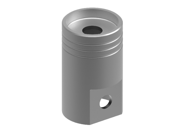
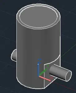
The final model should look something like this image in 3D.
This exercise is extracted from Viktor Rask’s e-book called 101 CAD Exercises – Learn & Improve Your Skills. Screenshots below are from Viktor’s original blogpost back in 2017.
He created this exercise series to help others speed up their learning process and make it more hands-on and fun. If you want more exercises like this, you can get them here.
Note that the exercises are 2D and 3D drawings without instructions so that they are not specific to AutoCAD. You can practice using other program if preferred.
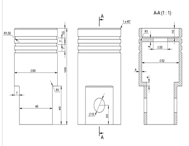
The piston 2D perimeter is below. The dimensions shown below are originally metric. However, for the purpose of this exercise (as because it is all proportional anyway), you can use the same values with imperial units if relevant.
You can also download the finished Piston 3D model here.
Tips from the author: Explore gridmode (F9) and snapmode (F7) to help navigate between drawing tasks.
Let’s get started.
- Draw a circle with a diameter of 60 and place its center on the origin (0,0).
- Draw a 23 length horizontal reference line from the origin.
- Draw a rectangle from the end of the reference line. The exact size is not critical as long as it is larger than the circle.
- Then mirror the rectangle using the (0,0) for mirror line. Delete the reference line.
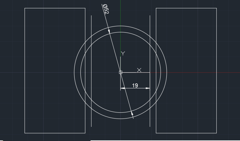
- Offset the circle. Set offset distance to 4. You will get a smaller circle with diameter of 52.
- Draw a vertical line at the centre of the circle (longer than the circle itself). Offset by 19 units both to the left & right of the centre line. Then delete the centre line.
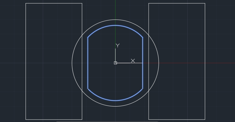
- Use TRIM command and the 2 vertical lines as edges to trim the inner circle.
- Repeat TRIM command, this time choose the arc as edges to trim the excess vertical line.
- Then use the JOIN command to make the following shape in the center.
- Switch to 3D viewpoint (Isonometric) for the next steps for easy viewing.
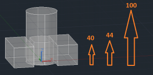
- Use EXTRUDE command to make the 2D shapes created in the previous steps to a 3D model. Move cursor to the Z direction and type in 40 units the 2 x rectangles, 44 units for the “rounded rectangular” in the middle and 100 units for the circle. Choose x-ray visual style to see the wireframe & shading as shown below.
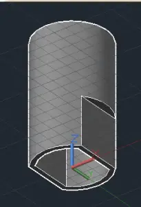
- Then using SUBTRACT command to cut out the 2 x rectangular and rounded rectangular shapes from the main cylinder. (Select the main cylinder first, enter, then select the objects to be subtracted). Note: You may need to change your viewpoint or visual style in order to select and subtract the central shape. You should now have a model similar to the one above.
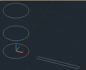
- Next, we are creating more 2D shapes. To make it easier, draw these outside of the main 3D cylinder. Draw a 52 unit diameter circle and a rectangle (7.5 unit high by 100 unit long).
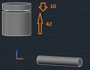
Create 2 more circle using COPY command. Move cursor in the z-direction, 44 units for the 1st circle and 100 units for the 2nd copy. Delete the base circle. - EXTRUDE the 2 circles to create “vertical cylinder”; the lower circle should be 42 units upwards and the circle on top should be 10 units downwards.
- Use the REVOLVE command for the rectangle to transform it into a “horizontal cylinder”. [Revolve – Enter – Select the rectangular, Enter, Select the axis start and end point (the long edge) – Then use the default 360° revolution]
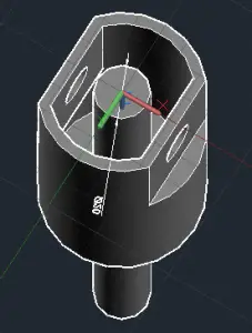
- Use the MOVE command and select the 2 x newly created “vertical cylinder”. Select centre of top cylinder face as the base point and move and snap to the centre of the main cylinder top face.
- Now we need to move the “horizontal cylinder” to the position shown in the image below. First, align the bottom node of the cylinder to the midpoint of the flat pane. Then move 20 units in the z direction and move towards the piston body in x direction so that so that it extends on both sides.
- Now SUBTRACT the 2 x inserted cylinders from the main body. You can use the Bottom view for easier access.
- Then create a 20 unit diameter circle and extrude it so it extends beyond the main cylinder. Then SUBTRACT to create a hole on the top face.
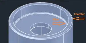
- Next, we will use the CHAMFEREDGE command for the outer edge of the top face of the cylinder. Type “d” to choose distance from the edge. Type 1 unit as the distance and then press Enter and repeat the distance -1 and enter to finish.
- For the inner edge of the top face of cylinder, use FILLETEDGE command as shown in the image below. Type “r” to select the radius. Choose 1 unit as the radius and press Enter.
- The final component to the piston is the ring grooves on the outer wall. To create this, we will use the TORUS command. Set the center of to the origin (0,0) and then select diameter (d) and type 60 units and then type 3 units as the thickness or radius. Make another 3 x ring duplicates (using the COPY command) with the following values in the z-direction: 76, 83 and 90 units. Then delete the original torus. You may want to use isolate (hide) the main body for this step.
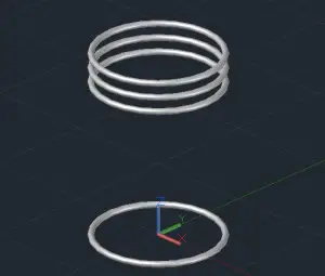
Finally, subtract the 3 torus from the main piston and voila, your 3D piston is completed. You should now have a final model similar to the one at top of the page.
For more drawings that you can use to practice your skills, be sure to 101 CAD Exercises – Learn & Improve Your Skills.
Any questions about this tutorial? Do you have any tips to help make this tutorial easier? Did you find this tutorial helpful? Leave a comment! And please share the knowledge using the Share buttons below!
He has recently started to adopt Revit in his architectural practice for 3D and BIM functionality.
- Which CAD Software Should You Learn to Begin Your Career as a CAD Operator in 2024? - March 29, 2024
- How to use Chat GPT to create AutoCad lisp - March 15, 2024
- The Advent of Generative Design: Autodesk’s Fusion 360 and AI Integration - March 8, 2024


I love these tutorials. Please keep on sending more of these exercises