
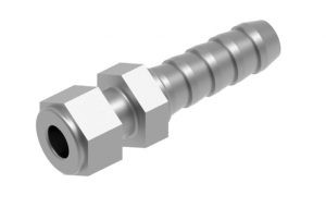
The revolve command or tool is a 3D modeling method that enables the user to create a solid following a certain path with a central axis, think of the ARRAY tool, only in three-dimension.
Let’s start by preparing the drawing by specifying crucial dimensions such as the inner and outer diameter of the threaded screw. Prepare the cross-section as well.
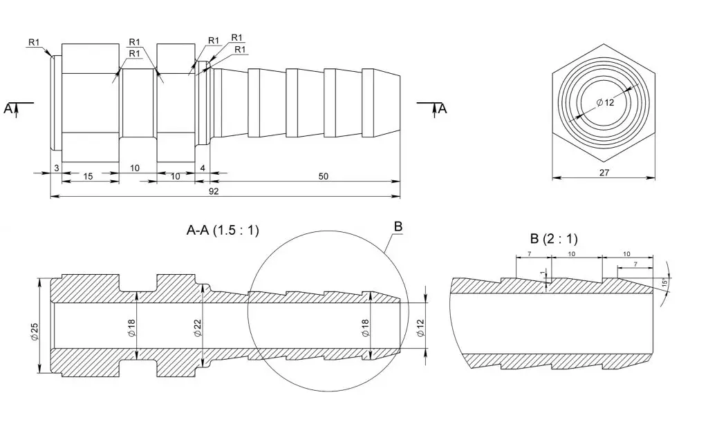
1. Open a new drawing. Insert the plan into the top view and cross-section. Make sure they are closed polylines and note the centerline or reference point for the object.
2. Switch to Elevation (Front) then adapt the UCS to snap the section into the inner diameter.
3. From there switch to 3d Isometric. Use the REVOLVE command. Click the Polyline (Elevation). Then trace the direction of the parallel axis line (vertical or horizontal) in the center. Enter 360 as the value of rotation. You now have a complete screw
4. Note that, the parts where there are hexagonal washers, we can trim it by switching to the UCS parallel to the head of the screw and subtract excess from the circle.
You can also do the hexagonal solids separately then assemble and combine it. That’s it! Your 3d screw is now complete.
For more drawings that you can use to practice your skills, be sure to check out our previous AutoCad 3D modelling step by step tutorial to draw a 3D piston and this e-book with 101 CAD Exercises – Learn & Improve Your Skills.
Any questions about this tutorial? Do you have any tips to help make this tutorial easier? Did you find this tutorial helpful? Leave a comment! And please share the knowledge using the Share buttons below!
He has recently started to adopt Revit in his architectural practice for 3D and BIM functionality.
- Which CAD Software Should You Learn to Begin Your Career as a CAD Operator in 2024? - March 29, 2024
- How to use Chat GPT to create AutoCad lisp - March 15, 2024
- The Advent of Generative Design: Autodesk’s Fusion 360 and AI Integration - March 8, 2024


Leave a Reply