Today’s post is from Jason Bewerk. Jason is a blogger and CAD-enthusiast. He works full-time at a design firm and enjoys helping others with CAD and thus started 12CAD.com to provide detailed tutorials and exercises for everybody to use.
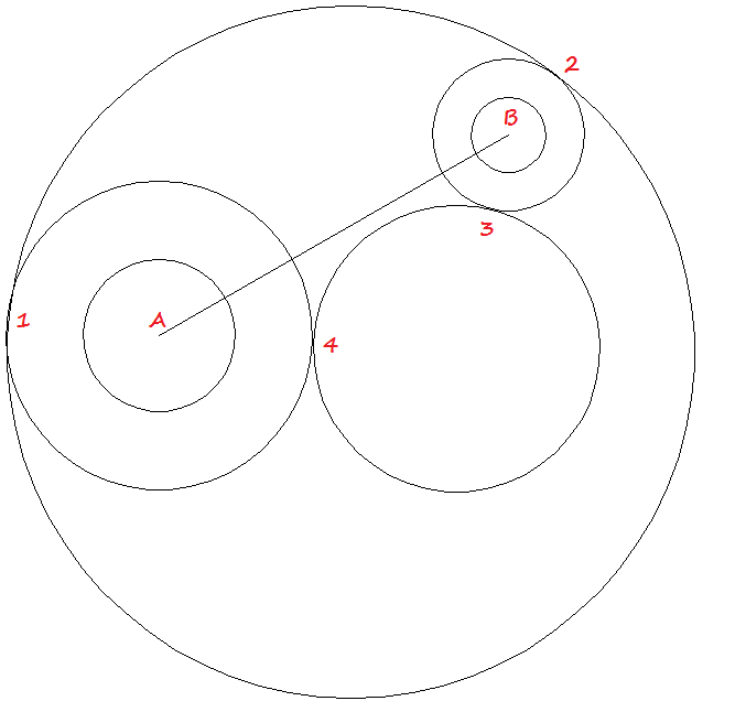
In the exercise below, you don’t draw the entire figure, but just focus on creating the circles that would be the basis for the figures perimeter.
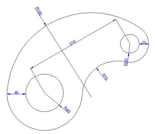
We have the image below to replicate, and luckily we are given all dimensions, which will make the task simpler. Today’s difficulty is simply to learn how to draw a circle with specified radius tangent to two objects. As you can see from the figure below, we need to be able to create the R180 circle and R75 circle.
The line AB in the figure below forms an angle of 30 degrees with the horizontal. To draw this line, follow these steps:
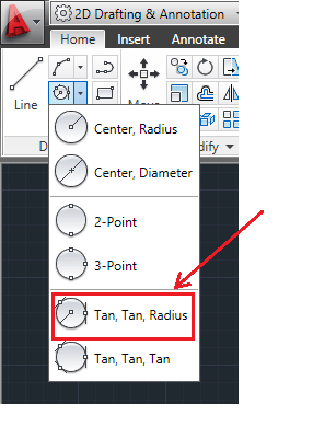
Find this command and use it to draw the two large circles. I hope this exercise was simple and you were able to complete it. If you had trouble, please check the previous exercises. Otherwise, I look forward to having you here for Day 9’s exercise.
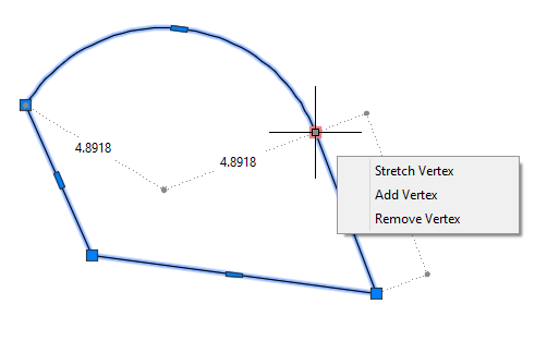
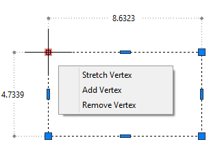
Multi-functional grips have been around since AutoCAD 2012 and they give you a menu of options when you hover over a grip or right-click a selected grip. Here you see the multi-functional grip menu for one of the vertices on a polyline.
By default, you can also repeatedly press the Ctrl key to cycle between the options on the menu. For example, in the figure you see here, if you select the grip that’s highlighted and press Ctrl twice, you’re up to the Remove Vertex option. You see a prompt to pick to remove the vertex.
I find this Ctrl method pretty confusing. Since you don’t see the options, so you don’t really know which option you’re up to–you have to guess by the prompt. Also, the instruction that you can use Ctrl to cycle through the options appears so briefly when you select a grip, that you don’t have time to read it. Is that your experience?
Do you find this menu annoying?
If you hover your cursor over a grip, the menu pops up automatically. You can turn this off using the GRIPMULTIFUNCTIONAL system variable. The setting is saved in the Windows Registry, so it persists from drawing to drawing.
Here are the values:
0: Multifunctional grip options are not available. This gets rid of the menu completely. 1: You can access multifunctional grip options by pressing Ctrl repeatedly (Ctrl-cycling). This gets rid of the menu, but you can still press Ctrl repeatedly to cycle through the options. As I mentioned, I find this option hard to use. 2 You can access multifunctional grip options using the grip menu displayed when you hover over a grip. If you don’t use Ctrl cycling, this is essentially the same as option 3. 3 You can access multifunctional grip options with both Ctrl-cycling and the grip menu. This is the default.
Have you changed the GRIPMULTIFUNCTIONAL setting? Which one do you use? Leave a comment!
Do you ever want to know the best mouse for AutoCAD? I asked subscribers and readers like you and these 6 specific mice were the ones that were most recommended. They include programmable, 3D and compact mice. And a trackball. See what might work for you!
High-precision trackball features a comfortable thumb-controlled design that is ideal for extended right-handed or left-handed use. Large trackball improves control while reducing hand and wrist motion. Fingertip control allows fast, accurate cursor movement. Marble optical technology delivers smooth, ultra-precise tracking. Customize buttons with included MouseWare software. WebWheel software optimizes Web browsing. PC and Mac compatible Trackman Wheel includes a USB to PS/2 adapter.
Compact and ultra-light, SpaceNavigator for Notebooks is the perfect travel companion for 3D designers and enthusiasts. Designed for mobile professionals and enthusiasts, the compact SpaceNavigator for Notebooks is only half the weight of its desktop counterpart. A small footprint makes it easy to use-even on airline trays-and a travel case makes transport effortless.
This hand-friendly wireless trackball lets you work and play wherever you want. No mouse to move around. No tricky keypad leaving your hand feeling cramped. Just roll the ball with your thumb and click.
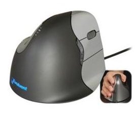
4. Evoluent VerticalMouse A fellow AutoCAD user said, “I love my Evoluent Vertical Mouse (been using it for two or three years now). Much easier on the wrist than the conventional hand-over-the-top-of-the-mouse style. I use the corded one. I don’t install the software, just plug it in and use it normal like (so no conflicts with my other software).” It comes in 3 sizes, wired or wireless, and is available for left- and right-handers.
From the Amazon product description: It’s the mouse you have to experience to believe! From here on in, you’ll control your computer with ultimate precision. With its powerful MX optical engine, the MX500 responds to even your fastest movements instantly. Wide choice of button assignments and control adjustments
Do you have a favorite mouse to use with AutoCAD? Leave a comment! If you can add an Amazon link, that will help others buy it from a reliable source.
Do you have REALLY old AutoCAD drawings? Many people keep drawings for years and years. But some older settings may make editing difficult. Here are some ideas for updating your old drawings.
Blocks without previews or descriptions
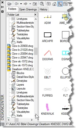
In older versions of AutoCAD, blocks didn’t have previews, like the kind you now see in the DesignCenter or ContentExplorer. You can also use them in the Tools Palette.
You can use the BLOCKICON command and press Enter at the first prompt to automatically create preview icons of all the blocks in a drawing.
Also, you can navigate to the drawing in DesignCenter, click the Blocks item, and AutoCAD will automatically generate block previews.
Associative dimensions
Before AutoCAD 2002, dimensions weren’t associative. That means that they weren’t really connected to the objects they measured. Now, the DIMASSOC system variable is set at 2 by default, which creates associative dimensions. The dimension is all one object and if you edit the object it measured, the dimension automatically adjusts to the new measurement.
If you open an older drawing (or one that uses an older template), set DIMASSOC to 2 by typing dimassoc, pressing Enter, typing 2 and pressing Enter again. But that will only take care of new dimensions that you draw.
To attach existing dimensions to their objects, use the DIMREASSOCIATE command:
Go to Annotate tab, Dimensions panel (expanded), Reassociate.
At the prompt, select the dimensions that you want to reassociate. You can use the Dissasociated option to select all dimensions that aren’t associated with an object.
Follow the prompts, which vary according to the type of dimension. You’ll be specifying an association point on the measured object to connect it to the dimension. You’ll see an association point marked by an X.
Continue to follow the prompts for each of the dimensions.
After you create a block with attributes and give the attributes specific values, you can edit block attribute properties with the Block Attribute Manager — the BATTMAN command. I explain how to create attributes (and why) in “Tutorial: Create attributes.” The attributes that you can edit are:
To start BATTMAN, choose Home tab, Block panel (expanded), Attribute, Block Attribution Manager. This opens the Block Attribute Manager dialog box, as you see here.
The column names you see here are Tag, Prompt, Default, and Modes. You can stretch the dialog box by dragging on its right side to make it wider. You can also click the Settings button to change which columns you see.
From the Block drop-down list at the top, choose the block that you want or click the Select Block button. Here’s how to use the BATTMAN dialog box:
Tag name, prompt name, and default value: Select the row with the attribute that you want to edit and click the Edit button. The Edit Attribute dialog box opens. On the Attribute tab, use the Tag, Prompt, and Default textboxes to make the desired changes. Click OK to return to the BATTMAN dialog box.
Prompt order: The prompt order is determined by how you selected the attributes when you created the block. To change the block order, select one of the rows and click the Move Up or Move Down button as necessary.
Visibility: Select the row with the attribute that you want to edit and click the Edit button. The Edit Attribute dialog box opens. Check or uncheck the Invisible checkbox and click OK.
Text style, justification, etc.: Select the row with the attribute that you want to edit and click the Edit button. The Edit Attribute dialog box opens. Click the Text Options tab and use the settings to change the text style and other text options. Click OK.
Properties such as layer, linetype, etc. Select the row with the attribute that you want to edit and click the Edit button. The Edit Attribute dialog box opens. Click the Properties tab and use the settings to change the layer, linetype, color, and other properties. Click OK.
When you make changes, existing blocks are immediately updated.
When you’re done, click OK to close the BATTMAN dialog box.
Tested in AutoCAD 2015.
Do you have any questions or tips for using BATTMAN? Leave a comment!
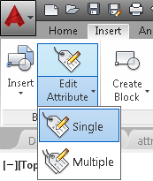
When you create and insert a block with attributes, you provide values for each of the attributes. But if you made a mistake or the value changes, you need to edit the attribute’s value. You use the EATTEDIT command for editing the value of a block attribute. Here are the steps:
At the Select a block: prompt, select the block with the attribute values that you need to change. The Enhanced Attribute Editor dialog box opens.
Click the attribute whose value you want to change.
Depending on your version of AutoCAD, either select the value in the Value text box and type a new value or click the Open Multiline Editor button at the right to edit the value in your drawing and click OK in the Text Formatting toolbar.
Click OK to close the dialog box.
Do you have any tips for editing attributes? Leave a comment!
This is a guest post by Eric M. Hoover, whois a Social Media and Content Strategist, building global marketing campaigns for a wide variety of brands. Eric has a fondness for automotive and architectural design, and previously developed website strategy for major automakers and renewable energy companies. He was introduced to me by Anne-Charlotte Lambert of SEER Interactive, an SEO agency that works with Autodesk.
—————–
Computer aided design has been around since the early 80s, but it’s never had as much of an impact on architecture, science and art as in in recent years. AutoCAD has been used to engineer some of the world’s most elaborate buildings or and scale some of science’s most intricate molecular models. Or, for some artists, it’s the only way to efficiently design a giant dinosaur out of LEGOs. Whatever the industry – whatever the project – AutoCAD has made what once seemed impossible, probable. The potential to bring even more imaginative ideas to life is growing daily with avenues into stop motion, 3D printing and more.
Check out how AutoCAD is making waves in industries around the world.
Virtual cinematography worlds
Think back to the ‘80s when special effects first took hold of the film-going public’s eye. Fast forward to the 1990s when video game systems such as SEGA Genesis and Super Nintendo — and later the Playstation and N64 –transformed graphics from flat 2-dimensional sprites into beautiful, 3D renderings. What seemed like such a big breakthrough then pales in comparison to today’s CGI and virtual cinematography. Whole new worlds have been created using 3D animation that looks impossibly real to the human eye. For the first time ever, filmmakers and video game designers truly have no boundaries when it comes to replicating their imagination. All they have to do is dream a special effect and, with computer-aided design, they can finally create it. As an example, see this article on how Autodesk is developing virtual production with James Cameron and Weta Digital.
Wheelchairs
Wheelchairs, in some form, have been around for centuries. While nothing quite as technologically advanced as the X-Men’s Professor Xavier’s hover chair has been created just yet, AutoCAD is making huge breakthroughs in the industry for paraplegics. One such innovation is Magic Wheels. Going up and down steep inclines is taxing and often problematic for even the strongest wheel chair users. However, Magic Wheels integrates a user-centered design and mechanical engineering features such as dual gears, brakes and hill-holding technology into a lightweight wheel drive and hand rim. With Magic Wheels, the painstaking process of wheelchair users manually wheeling themselves around could be a thing of the past.
This video is a basic operation guide for MagicWheels.
Sports Shoes
From the original handcrafted waffle-like design to 3D printed kicks, Nike has always been a pioneer at the forefront of sportswear. With AutoCAD, the manufacturing giant continues to innovate by creating sports shoes influenced by the player’s unique game, biomechanics and movement of the player. Sneakers simply aren’t simply shoes anymore — they’re an extension of the player that maximizes performance in a way never imagined before.
Molecular renderings and human organs
Forget about the Tinker Toy models you created in high school chemistry class. AutoCAD may actually have its biggest influence and beneficial impact in advancing the field of science. For example, a 3D-printed 10,000,000:1 rendering of DNA-RNA transcription was created using specific data that was fed into AutoCAD at Harvard University. This type of breakthrough has already led to functioning 3D printed organs, such as hearts, lungs, and more. Who needs the Fountain of Youth when you can simply map, print and implant new, functional organs? Read how Autodesk and Organovo teamed up to bring printable human organs closer.
Bridges
Well, you probably did know that AutoCAD could be used to design bridges, but this is an interesting story. During its infancy, skeptics were worried that the San Francisco Bay Bridge, the world’s largest suspension bridge, wouldn’t be able to support the strain of rush hour commutes. Read how the California Department of Transportation silenced the critics by sharing detailed 3D visualizations using computer aided design to validate that the project was viable and ultimately safe.
What’s next?
These are just a few of the achievements that AutoCAD has helped bring to fruition. As time goes by, there will undoubtedly be many more imaginative uses for this software, helping to bring out the best in tomorrow’s most innovative minds.
What innovative ways are you using AutoCAD? Or perhaps you can share a link to an interesting story of how AutoCAD has been used. Leave a comment!
Another year, another AutoCAD release. Autodesk has been pretty reliable that way for years. Here’s my list of new features — along with my opinion, when I have one.
New way to start — and switch among — drawings
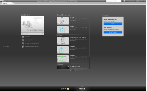
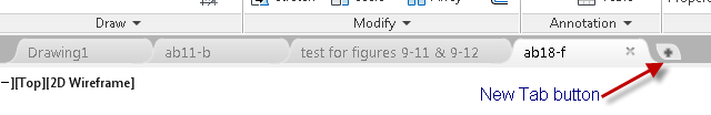
Several times, Autodesk has tried to add a “front” to AutoCAD. Remember the Today page? Then they take it out. Here’s what you now see when you start AutoCAD.
You’re actually on a tab that’s called New Tab. More about that in a minute.
At the bottom are two links. By default, you’re on the Create page. If you click the Learn link, the page slides to show you some training videos, tips, and online resources.
On the Create tab, there are 3 columns:
Get Started: Here you can click Start Drawing or choose a template, open files, open a sheet set, get more templates online, and explore sample drawings.
Recent Documents: Here you see thumbnails of recent drawings that you opened. You can click one to open the drawing.
Connect: here you can sign in to Autodesk 360 or send feedback.
If you click Get Started, Drawing1 opens and there’s still a tab at the top. You can click the New Tab button (it looks like the New Tab button on your browser) to get the same 3-column screen you see when you open AutoCAD — there you can start a new drawing or open and existing one. By the way, layout tabs similarly have a New Layout button.
The big deal is that each drawing that you open, whether from a tab or by using the OPEN command, has its own tab. Now it’s really easy to switch among drawings.
What I think: I’m not a big fan of “covers.” But I love the new tabs.
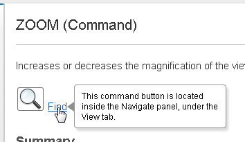
Animated help
In the Help system, if you click the tool you want to use or its Find link, an animated arrow shows you where the tool is on the ribbon. If the tool isn’t on the ribbon, a message tells you which ribbon tab and panel it’s on.
This is helpful for newbies. In fact, anyone might use this feature for tools that aren’t on the ribbon, because it seems like they keep taking stuff off it! For example, the View tab, although it has plenty of room on it, doesn’t show the following panels:
Views
View Styles
Coordinates
Navigate
So the tool will tell you where to find the ZOOM command on the ribbon, for example, as you see here.
To display any of the missing panels, right-click in a gray area of the tab and choose Show Panels. Then choose a panel.
By the way, they’ve taken several buttons off the status bar, too. To get them back, click the Customization button at the right end of the status bar and choose the button that you want to see.
What I think: As I said, this is helpful, although I don’t like that so much has been taken off the ribbon.
Check out this free dynamic block tutorial
Plus get free tips in our AutoCAD Tips Newsletter!
Get a free tutorial on creating a complete dynamic block, including a drawing to practice on. You'll make a movable chair, resizable desk, and more. PLUS, the highly-acclaimed AutoCAD Tips Newsletter will keep your skills up to date!
There’s a new dark color scheme. It’s supposed to minimize eye strain. To change it, start the OPTIONS command and on the Display tab, choose the Light option from the Color Scheme drop-down list.
OK, I’m getting old and my eyes aren’t as good as they used to be, but I find the dark scheme doesn’t have enough contrast and I can’t distinguish anything. So I changed it to light. I still have trouble reading the black ribbon tab names against the dark gray background. Talk about lack of contrast!
What I think: Let me rant here. Autodesk changes its interface almost every year. I should know, because it means I have to redo zillions of screenshots for my book each year. Mostly the changes are unnecessary — the don’t help anything. Really. I hate the dark color scheme and even the light one doesn’t work well for me.
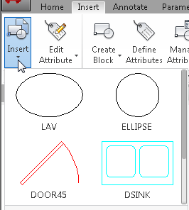
Insert blocks from the ribbon
If you have blocks stored in the drawing, you can insert them from the ribbon. What could be easier? You can do the same for dimensions, mleaders, text, tables, and table cells.
What I think: Nice!
New selection look and lasso selection
Selected objects look different. Instead of being dashed, they are thickened and highlighted.
Lasso selection is a new way to select objects. You click in a blank area and drag around objects. Release the mouse button when you’re done. Anything that crosses the lasso boundary is selected.
Watch the video:
Command preview
You can see the result of TRIM, EXTEND, LENGTHEN, BREAK and MATCHPROP commands before you select the objects to see if the result will be what you want. This should reduce the number of undo operations that you have to use. For example, when you are trimming an object, after specifying the cutting edge, you can hover the cursor over the object you want to trim and see the result before selecting the object.
What I think: Very helpful!
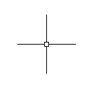
Cursor badges
When you are doing certain operations, there’s an icon, called a badge, at the cursor to let you know what operation you’re doing. For example, you’ll see a quesrtion mark badge for LIST, ID, and other inquiry tools. You’ll see an X when you use the ERASE command. Likewise, there are badges for COPY, MOVE, SCALE, and ZOOM.
The crosshairs no longer appear inside the pick box so you can more easily see what you’re picking.
What I think: I really don’t see the use for the badges. I always know which command I’m using. In fact, it’s easier for me to remember which command I’m using than to remember what the badges mean. But I like the empty pickbox.
New viewport controls
You can more easily resize model space viewports by dragging on their boundaries. The active viewport is more clearly delineated with a light blue boundary. You can press Ctrl and drag to split a viewport or remove a viewport by dragging its boundary to the edge of the screen.
New Mtext features
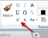
Bullets and numbering are automatic. AutoCAD automatically switches your case if you press the Shift key while Caps Lock is turned on. Subscript and superscript text is easier to create with new buttons on the Text Editor ribbon.
There’s a Match Properties button in the Mtext Editor to make it easier to copy Mtext properties.
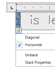
Fractions are easier, too. You just type a forward slash and AutoCAD stacks it. While editing the text, you see a stacking icon and you can click it to control the fraction.
The new TEXTALIGN command lets you align multiple single-line text or Mtext objects. This isn’t left or right aligning; it’s aligning the text objects with each other to that they don’t look sloppy.
Geographic location enhancements
The geographic location feature lets you set the geographic location from a map. (If you want to access online map data, you need to be signed into your Autodesk 360 account.) Using online data lets you specify a location and place a marker by entering an address or zooming in on the map. You can also embed and plot map data. It’s kind of like downloading Google maps into your drawing — at least for the area you specified.
And a few more…
Easier access to isometric drawing tools
Point cloud enhancements
A new translation framework (ATF) imports data from CATIA, Pro Engineeer, SolidWorks and other formats, supporting meshes, curves, object colors, and layers.
There’s a new add-in, called Autodesk BIM 360.
You can create button images for the ribbon in PNG image format.
What do you like — and not like?
And what new features would you like to see? Leave a comment!
Recently, a reader asked how to plot to a specific scale from model space.
Ordinarily, I recommend plotting from paper space. You have better tools there for laying out your drawing and inserting a title block. But you can also plot from model space. In fact, this is the original method for plotting in AutoCAD, many years ago.
Here are the steps:
From the Model tab, click the Plot button on the Quick Access toolbar or choose Output tab, Plot. This starts the PLOT command and opens the Plot dialog box.
If necessary, choose your printer/plotter from the Name drop-down list.
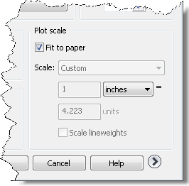
Look in the Plot Scale section at the lower-right corner of the dialog box. By default, Fit to Paper is checked, as you can see on the right.
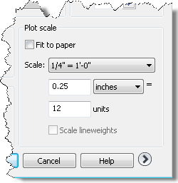
Uncheck the Fit to Paper checkbox.
Click the Scale drop-down list and choose the scale that you want. In the figure below, I chose 1/4″ = 1′-0″. This is a common architectural scale in the United States.
To check what the result will look like, click Preview. Click the X (Close) button on the Preview toolbar to exit the preview (although you can plot directly from this screen).
Click OK to plot.
Do you plot from model space? If yes, why don’t you use paper space? I’m just curious. Leave a comment!
Multifunctional grips are small, contextual menus that let you edit the properties of an object or component. Use them to quickly edit objects.
For example, when you draw a rectangle, each vertex has multifunctional grips that let you add, remove, or stretch that vertex.
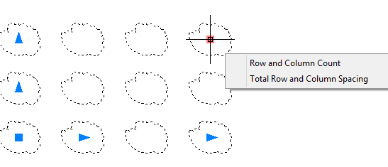
Similarly, an array has multifunctional grips that let you edit the number of rows in a rectangular array or the angle between items in the polar array.
How to use a multifunctional grip
To use a multifunctional grip, follow these steps:
Select the object.
Hover over a grip.
Choose one of the options that appears.
You can also make a grip “hot” by clicking it and then right-clicking it. Along with the other shortcut menu items, you’ll find the multifunctional grip options.
Multifunctional grips have been expanded since they were introduced. For example, the rectangle’s center grip menu also lets you convert the side of the rectangle to an arc. Watch the video to see how it works.
Which objects have multifunctional grips?
The key to using the multifunctional grips is to know which objects have them. Here’s a rundown:
2D objects: Lines, polylines, arcs, elliptical arcs, splines, arrays, and hatches. Also dimensions and multileaders
3D objects: 3D faces, edges, and vertices
Control multifunctional grips with a system variable
The GRIPMULTIFUNCTIONAL system variable lets you control how multifunctional grips work. The default setting is 3 which gives you the behavior I described above; it’s a combination of the 1 and 2 settings. Here are the other settings:
0: Multifunctional grip options are not available
1: Access the options by pressing Ctrl to change grip behavior (Ctrl-cycling)
2: Access the options using the grip menu that you see when you hover over a grip
Are you using multifunctional grips?
Are you using this feature or is it new to you? Leave a comment and share your experience!
Important: While we don't collect cookies, some of our 3rd-party services (such as PayPal and WordPress) do, to give you a safer and better browsing experience. Read about how we use cookies and keep your personal information secure by reading our Privacy Policy here.