
Recently, a reader asked how to plot to a specific scale from model space.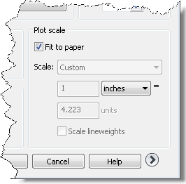
Ordinarily, I recommend plotting from paper space. You have better tools there for laying out your drawing and inserting a title block. But you can also plot from model space. In fact, this is the original method for plotting in AutoCAD, many years ago.
Here are the steps:
- From the Model tab, click the Plot button on the Quick Access toolbar or choose Output tab, Plot. This starts the PLOT command and opens the Plot dialog box.
- If necessary, choose your printer/plotter from the Name drop-down list.
- Look in the Plot Scale section at the lower-right corner of the dialog box. By default, Fit to Paper is checked, as you can see on the right.
- Uncheck the Fit to Paper checkbox.
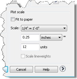
- Click the Scale drop-down list and choose the scale that you want. In the figure below, I chose 1/4″ = 1′-0″. This is a common architectural scale in the United States.
- To check what the result will look like, click Preview. Click the X (Close) button on the Preview toolbar to exit the preview (although you can plot directly from this screen).
- Click OK to plot.
Do you plot from model space? If yes, why don’t you use paper space? I’m just curious. Leave a comment!

Ellen Finkelstein is the author of the best-selling AutoCAD & AutoCAD LT Bible, which started with R14. Ellen has written extensively on AutoCAD, including articles for Autodesk’s website and features for AutoCAD’s Help system. Ellen’s first book was AutoCAD For Dummies Quick Reference.
Latest posts by Ellen Finkelstein (see all)
- Combine or subtract 2D shapes to create custom shapes - February 17, 2022
- Working with linetype scales - January 18, 2022
- Rename named objects–blocks, dimension styles, layers, and more - December 21, 2021


We plot in model space because our clients’ drawings are totally drawn in model space, including the title block. However we’ve learned a few tricks about plotting that way!
We typically plot to the drawing extents. We start the PLOT command. Set the plotter, paper size and plot style table. Make sure the plot scale is set to “Fit to paper”. Then we note what the scale is set to in the Units text box. It is grayed out but still readable. This will give you an idea about what common scale should be used. Uncheck “Fit to paper” and set the scale from the drop-down list. Always check the preview to make sure that it is what you want. When everything looks good, plot the drawing.
I teach AutoCAD to some young students who struggle to grasp some of the concepts (being polite about it!). If I give them an A3-sized border in model space, then all they’ve got to do is start drawing and they can print out 1:1 on an A3 sheet or ‘fit to paper’. Nothing easier…..
To start creating viewports and dimensioning in paperspace (which is, I believe how it’s done these days) they would fall at the first fence.
Would be interested in other peoples’ experiences – Many thanks
We use model space mostly at our place. The time it takes for paper space to regeneration is really a time lag for us. So here’s what we do. We have a title block that we saved at every scale we want right in our drawing template file (we shrunk them all up to the size of a 16″ x 10″ (12″ = “12”) block just to keep them out of our way. We print to 11 x 17 paper, so that’s how we get our nice margins. It works sweet. The blocks have the scale number on it So if it says 16, we type 16 in the box instead of looking up 3/4″ = 1′ in the drop down list (faster). The only time we print from paper space is when we use Acroplot Pro to create a single pdf file for us.
When I first came people were drawing and putting all sorts of notes on paper space and we kept going in and out and all sorts of things (AutoCAD 2005). We went to model space and its so fast and we never look back and not once regretted it. We’re a commercial cabinet business and we produce the standard architectural shop drawings.
The ting about AutoCAD, like all other programs, is that there is no one “right” way to use it. Whatever is fastest for you is what rules. This is the principle of Lean Manufacturing or a host of other books that simply say this: “What is the value in doing this?”
Sure, if we did other kind of work, we’d find other approaches more valuable. But we draw on one layer, directly in model space, have our drawings in a nice grid and pan around and copy around lickety split and have saved views that hyper jump us instantly all over the drawing where we need to go. Can’t beat this for our use of it.
We’re definitely sold on model space.
(One more follow-up. To make model space drawing work, we change the dimscale when we go to different sized title blocks. I worked out our basic templates so that all sizes are easy as pi(). Okay, easier than pi(). Page number is the scale divided by 5, title is scale divided by 7, dimension scale is scale divided by 13. Super small test is scale divided by 16. Other options are divided by 9 or 11. So if I have a 16 scale title block (3/4″ = 1′) and I want to change the dimscale to match dimensions and annotating in that block, I type dimscale and then type 16/13. If I move to a 24 scale block (1/2″ = 1′) then I type DSC (my shortcut for “DimScale Change”) and type 24/13. Whalah. Easier than pi(). I learned that AutoCAD accepts fractions of any size. So when I want to draw a line that is 80mm, although you can’t type 80/25.4 (that’s mixed decimals and fractions) I CAN type 800/254 and get the same effect. So now when I am drawing in mm, I do that with all sorts of things. 32mm is entered simply at the command line as 320/254. Etc. We also have a pallet of dimstyles as part of each title block and also hidden, dashed and center lines. So we use DR (Dim Restore) to activate one of those we’d like to us, or we use match property to change a one-off dimension we needed for a special situation. We even have a mini-cabinet with the architectural door opening lines in a large dash and the adjustable shelf in a smaller dash and so when we are drawing we just match prop them as we go. It takes a little set up the first time, but then after that, it’s a done deal. That’s how we solved all the other problems you might normally face. We find it very liberating. Again, though, our work allows us to do this – and for our work this is way faster than messing with paper space in the least. But I would agree that others will find other methods better. It all depends on what you need and what is fastest for you!)
I do not disagee with anything written so far. The following describes one way for setting the drawing up using units, limits, and the intended plot scale suitable for drawings created entirely in model space. Also, the description applies to other settings besides the plot scale setting. Arguably there are different ways to accomplish this but this method will work regardless of the release of AutoCAD. It was the method used prior to paper space and all of the additional features added to AutoCAD.
Hope I have not misinterpreted the post.
3/64” = 256
1/16” = 192
3/32” = 128
1/8” = 96
3/16” = 64
1 /4” = 48
3/8” = 32
1 /2” = 24
3 /4” =16
1” = 12
The table above is used for architectural drawings.
To determine the scale factor for the intended plot scale divide 12 by the decimal fraction equivalent.
Example for a 3/16″=1′-0″ intended plot scale:
3/16″ = 0.1875 decimal equivalent
Divide 12 by 0.1875 = 64 which is the scale factor used to set the limits of the drawing and is also the scale factor used for the “Ltscale” variable which controls line type spacing in AutoCAD drawings. The same scale factor is used to insert blocks that need to be scaled into the drawing and for setting the text height based on the intended plot scale.
Determine the horizontal and vertical distance of the objects to be portrayed, including any additional information required that is to be shown within the available space of the borders. Divide the horizontal distance by the desired horizontal distance of the sheet. Do the same for the vertical distance. Round up the result to the nearest whole number for the scale.
Assume the following:
The drawing shall reside in model space as will the border sheet using a 24×36 sheet format. The drawing area requires a floor plan which is 60′ in the horizontal direction (west to east) and 40′ in the vertical direction (south to north). Divide 36 by 60 equals 0.6, divide 24 by 40 equals 0.6. An equivalent scale of 1/2″=1′ (0.5) could be used to fit the drawing within the 24×36 sheet format with room for additional information. The actual scale factor for 1/2″ would be 1/2=0.5, 12 divided by 0.5 equals 24. Multiply the width of the sheet (36 times 24 equals 864 inches) and the height of the sheet (24 times 24 equals 576 inches) to determine the drawing limits.
Set the units to architectural with 1/16” accuracy.
To set the limits of the drawing:
Create a layer named “Plot Limits”, line style continuous
Draw a 864″x576″ rectangle with the lower left corner at 0,0.
Issue the “Limits” command and set the lower left corner to 0,0, set the upper right corner to 864,576.
Insert the border 24×36 border sheet at 64.
All real world elements are then drawn to actual size, do not scale. Set the line type scale factor “Ltscale” to 24. This factor will be used to scale the line types, scale block inserts that require scaling, and for adjusting the text height for the intended plot scale of the drawing. This factor will also be used when setting the dimension styles.
The plot scale would be 64
Decimal of a foot commonly used for civil engineering drawings use the scale factor 1, 10, 20, 30, 40, 50 and so on.
Assume the following:
The drawing shall reside in model space as will the border sheet using a 24×36 sheet format. The drawing area requires a site plan which is 1000′ in the horizontal direction (west to east) and 900’ in the vertical direction (south to north).
In this example a 1”=50’ decimal engineering scale will provide ample room for the site.
Set units to decimal with 0.00 accuracy.
To set the limits of the drawing:
Create a layer named “Plot Limits”, line style continuous
Draw a 1800×1200 rectangle with the lower left corner at 0,0.
Issue the “Limits” command and set the lower left corner to 0,0, set the upper right corner to 1800,1200. This assumes that coordinates or other geospatial units are not required.
All real world elements are then drawn to actual size, do not scale. Set the line type scale factor “Ltscale” to 50. This factor will be used to scale the line types, scale block inserts that require scaling, and for adjusting the text height for the intended plot scale of the drawing. This factor will also be used when setting the dimension styles.
The plot scale would then be set to 50
1:1
1:50
1:100
1:200
1:250
1:500
1:1000
The table above is for metric scales.
The common conversion factors are:
1 foot equals 304.8 mm or 0.3048 m
1 inch equals 25.4 mm or 0.0254 m
3.280833 feet equals 1 meter
To scale a metric unit drawing to an English drawing unit use 3.2808333
To use modelspace as your printable area presents many shortcomings (especially if its multiple pages with differing scales)like lineweights, linetype scales and exporting to PDF format. When I receive a drawing like that from someone else that I’m to finalize I immediately revise to paperspace format. Just cut the title block from model space, insert and align on a paperspace tab. The paperspace should be set to the sheet size (say “A” 11″ x 8.5″), use command MVIEW to create a viewport, command MSPACE to open viewport, find drawing for that page and zoom into it,to set to scale (say 1/4″=1′-0″) you use command ZOOM and enter 1/48xp, pan to fit, enter command PAPERSPACE to close viewport. Now if you have multiple drawing pages all you have to do is right click on that paperspace tab and copy it, click on new tab and you will have the same border and modelspace, type MSPACE to open viewport find next drawing and zoom into that, set its scale and close with PAPERSPACE again. Now you set LTSCALE to (usually) “1” and all linetypes on all pages are the same scale. Easy peasy. Note if the drawing is to scale then the titleblock will be scaled up (if its 1/4″=1′-0″) then you will need to scale it down to the 1 to 1 scale. That would be the command SCALE, select the titleblock, enter 1/48 and your good. Hope this helps.
I remember those dark days of drawing everything in Model Space. I can’t imagine going back there! Ahhhhh! Paper Space, where everything’s full size and 1:1, and viewports do all the work (Math)
your conversation regarding plotting scales has some how helped me.