You can easily stretch a circle with grips. To specify the new radius, just enter it on the command line (or in the Dynamic Input tooltip). But suppose the information you have is the difference between the two radii?
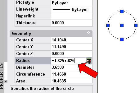
For example, let’s say that your circle’s radius is 1.825 and you know that you have to make it 0.625 larger. Of course, you can add the two numbers, but there’s an easier way.
Select the circle and open the Properties palette. For the Radius value, insert an equal sign (=) before the current radius. After the radius value, type +.625. Then press the End key on your keyboard (not Enter). The new radius appears in the Properties palette and your circle’s radius changes.
Ragnar Thor Mikkelsen contributed an even easier way. However, note that this tip doesn’t work if Dynamic Input is on. (To turn it off, just click the Dynamic Input button on the status bar.) Here are the steps:
1. Select the circle and click one of the quadrant grips to make it “hot.” 2. At the ** STRETCH ** Specify stretch point or [Base point/Copy/Undo/eXit]: prompt, type tk. 3. At the First tracking point: prompt, click the quadrant grip again. 4. At the Next point (Press ENTER to end tracking): prompt, move the cursor in the direction you want to stretch the circle and type .625 (in our example) or the change in radius you want and press Enter. 5. At the Next point (Press ENTER to end tracking): prompt, press Enter.
Scott Loadman also contributed an easier way:
1. Select the circle and click one of the quadrant grips to make it “hot.” 2. At the prompt, type b for the Base point option. 3. At the Specify base point: prompt, click the quadrant grip again. 4. At the Specify stretch point or [Base point/Copy/Undo/eXit]: prompt, move the cursor in the direction you want to stretch the circle and type the change in radius (.625 in our example) and press Enter.
Use AutoCAD’s calculator (originally the CAL command and then the QUICKCALC command) to find calculated points, such as the midpoint between two existing points or the center of a triangle. You usually use this command transparently, while drawing a line.
Use the object snap
There’s a shortcut to start a line (or specify any other point) midway between two points. At the prompt for the point, press and hold Shift and right-click. Then choose Mid Between 2 Points from the shortcut menu of object snaps.
Use QUICKCALC to draw a line between two endpoints
To start a line midway between two points with QUICKCALC, do the following:
Turn off OSNAP, so you don’t inadvertently snap to an object snap, especially if you’re near other objects.
Start the LINE command.
At the Specify first point: prompt, type ‘quickcalc (or just ‘qc) and press Enter.
In the expression box, type (end+end)/2 as you see here, and then press Enter.
QUICKCALC
At the >> Select entity for END snap: prompt, use the pickbox to pick a point.
At the >> Select entity for END snap: prompt, pick a second point.
Continue drawing the line. The line starts at the midpoint between the two points you specified.
Draw a line between two centers
To use circle centers, type (cen+cen)/2 and follow the same procedure.
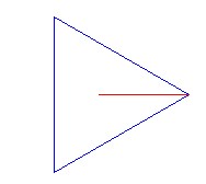
Start a line at the center of a triangle
To start a line at the center of a triangle, you use a similar technique:
Turn off OSNAP, so you don’t inadvertently snap to an object snap, especially if you’re near other objects.
Start the LINE command.
At the Specify first point: prompt, type ‘qc and press Enter.
Type (end+end+end)/3 in the QuickCalc expression box and press Enter.
At the >> Select entity for END snap: prompt, use the pickbox to pick a point.
At the >> Select entity for END snap: prompt, pick a second point.
At the >> Select entity for END snap: prompt, pick a third point.
Continue drawing the line.
The line starts at the center of the triangle, as you see here.
Line Drawing
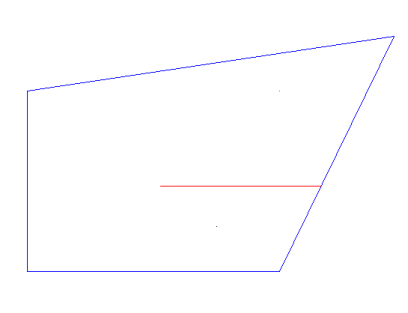
Find the intersection of two lines based on their 4 endpoints
Let’s say you want to start a line at the intersection of two lines, without drawing the two lines.
Start the LINE command.
At the prompt, type ‘qc and press Enter.
Type ill(end,end,end,end) in the QuickCalc expression box and press Enter.
At the prompts, select the endpoint of the first imaginary line, then its other endpoint. Then select the endpoints of the second line.
Continuing drawing the line.
Line Drawing
Tip: If you expand the Variables section of the QuickCalc dialog box, you can choose the ille variable to do the same operation.
If you create user-defined hatches, which means that you specify the angle and spacing, you may want to save them for future use. You can easily do this using a tool palette.
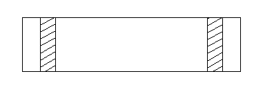
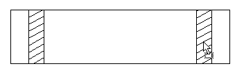
First, create the user-defined hatch. In the Hatch and Gradient dialog box (or on the Hatch Creation tab in AutoCAD 2011), choose User-Defined as the type. Use the tools to specify the angle and spacing.
This hatch has an angle of 30° and a spacing of 0.25 units.
A user-defined hatch pattern in AutoCAD
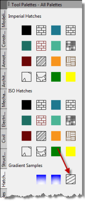
Open the Tool Palettes window. (View> Palettes> Tool Palettes, or the TOOLPALETTES command)
Click the Hatches and Fills tab.
Drag-and-drop cursor--for a hatch pattern
Select the hatch. Then click and hold until you see the drag-and-drop arrow, as you see here.
Then simply drag the hatch to the tool palette. Here you see the new hatch on the palette.
A user-defined hatch pattern on a tool palette
You can now drag this hatch into any closed area in your drawing.
Even better, because you have that hatch pattern saved in a tool palette, you can use it in any other drawing.
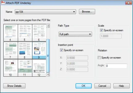
Lots of people use the PDF format. If you have a PDF image that you want to reference as you draw, you an attach it as an underlay, starting with AutoCAD 2010. This is similar to attaching an xref.
Choose Insert tab> Reference panel> Attach (the ATTACH command). You can also use the PDFATTACH command.
In the Select Reference File dialog box, choose a PDF file and click Open.
Top Customization Tips Every AutoCAD User Should Know
AutoCAD is meant to be customized, but customization is one of the most complex features of AutoCAD. Gain the knowledge you need to be a master at customizing AutoCAD!
AutoCAD 2011 has three new commands that help you hide selected objects or isolate them (hide everything except the selected objects).
The ISOLATEOBJECTS command hides all objects except those that you select. After selecting objects, right-click in the drawing area and choose Isolate> Isolate Objects.
The HIDEOBJECTS command hides selected objects. Select the objects, right-click in the drawing area, and choose Isolate> Hide Objects.
The UNISOLATEOBJECTS command undoes either of the previous commands, displaying objects that those commands hid.
For several releases, there has been a command to isolate objects by layer, the LAYISO command. By default, LAYISO locks and fades the other layers (objects not on the same layer as the object you selected). You can use the Settings option to turn those layers off instead.
The LAYUNISO command reverses the effect of the LAYISO command.
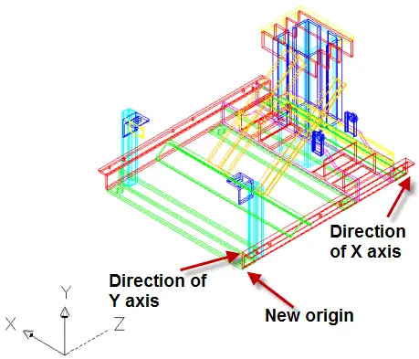
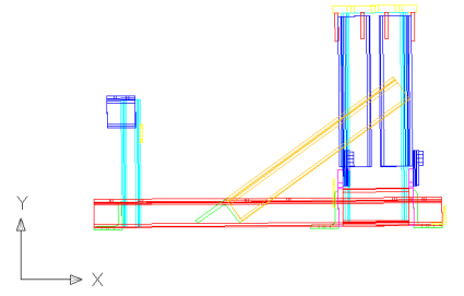
When you create a new User Coordinate System (UCS) in AutoCAD, by default, your viewpoint doesn’t change. Here I used the 3 point option of the UCS command to create a new UCS.
Create a new UCS with the 3 point option
Sometimes, you may want to return to plan view in that new UCS to get your bearings. You can do this with the UCSFOLLOW system variable. Type it on the command line and change its value to 1.
Then, when you create the new UCS, AutoCAD puts you in plan view for that new UCS.
I just finished teaching a 2-week AutoCAD class at the local University here (Maharishi University of Management). The course was part of the Sustainable Living undergraduate major program. It was a lot of fun and the students created amazing designs and fantastic drawings of those designs. Although the time was a little tight, they really learned an incredible amount. I taught in the morning and a co-teacher went through the exercises from my book in the afternoon.
I wanted to show the head of the department what the students accomplished and thought I’d send him a PDF. I was wondering how to combine all the drawings into a PDF and could have exported each one to PDF and combined them in Adobe Acrobat, but then I thought of the sheet set feature. The students had all created layouts with titleblocks. Here’s what I did:
I opened the Sheet Set Manager (View tab>Palettes panel>Sheet Set Manager).
From the drop-down list, I chose New Sheet Set.
In the dialog box, I named the sheet set and assigned it to a folder, in this case the folder where I had saved all of the students’ drawings. All of the files and their layouts were listed.
I clicked on each one to see a display of the layout. Because many of the drawings had a Layout2 tab that the students didn’t use, I was able to remove those by just looking at the display, right-clicking and choosing Remove Sheet. No need to open the drawings!
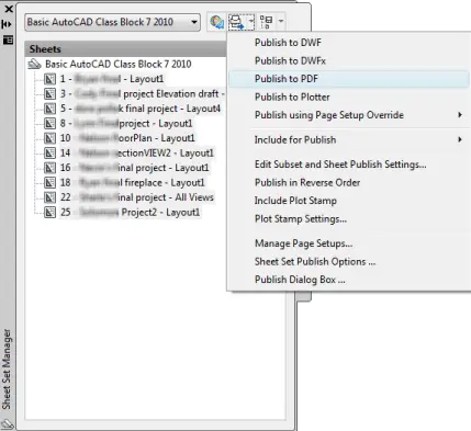
Then I selected the sheets, clicked the Publish drop-down arrow, and chose Publish to PDF. I chose a name and location and clicked Select.
That’s it! AutoCAD created the PDF.
Create a multi-page PDF from the Sheet Set Manager
It’s that time of year again, when Autodesk allows us beta participants out of our non-disclosure agreement and lets us finally discuss all of the new features! Each year I cover them in some detail, so you can decide if you want to upgrade.
What are the biggies? New 3D surfaces are probably the biggest new addition. Transparency is important enough that the new logo alludes to it. If you drag the desktop icon over other icons, you’ll see that the left side of the black bar is actually transparent.
The AutoCAD 2011 logo
Secondary grips on polylines are cool. And you create hatches on the ribbon now. (You can still use the dialog box if you want.)
Cosmetic changes
The grid has been reworked. Instead of dots, it looks like graph paper. It’s on by default in acad.dwt, which is meant to show it off, but is kind of annoying if you don’t use the grid that much. Of course, you can open acad.dwt, turn off the grid by clicking the Grid button on the status bar, and save. This won’t affect existing templates, because the grid setting is saved in the drawing.
AutoCAD 2011 grid
The default color of the background has changed yet again. Third time in three years. This is a touchy subject with many users! This time it’s dark gray. I stick to white because it makes for better images.
The UCS icon looks a little different. No arrows. Maybe they think it looks more modern.
AutoCAD 2011 UCS icon
The Help system is Web-based. You’ll be opening HTML files. As long as you’re connected to the Internet, they’ll be from Autodesk’s Web site. The new system takes a little getting used to.
There are 5 new predefined visual styles: shades of gray, sketchy, x-ray, shaded with edges, shaded. These just mean that you can usually find a look you like without creating a custom visual style. The x-ray visual style is especially nice for working in 3D; it gives you a sense of the solidarity of objects (unlike wireframe), yet you can see the back sides and edges of objects.
Parametric Constraints Updated
A new button on the status bar, Infer Constraints, automatically creates constraints based on your geometry.
You can relax constraints temporarily by pressing the Ctrl key. It’s easier to hide and show the constraints that you want. There are now individual commands for all of the GEOCONSTRAINT options, for less fussing to get where you want to go. For example to set a geometric constraint for parallel lines, you would use the GCPARALLEL command. The same is true for the DIMCONSTRAINT command; for example, there’s a new DCLINEAR command.
You can create parameter filters to help you display and hide just certain parameters.
Secondary Grip Editing
Polylines have grips at the midpoints of their segments, called secondary grips. You can use them to convert the segment to an arc (or to a line if it’s an arc), stretch it, or add a vertex. You can do the same with the traditional grips, now called primary grips.
New Transparency Property
Objects can now be transparent and you can set the transparency percentage. Transparency is an object property just like color and linetype, so you can create layers with transparency. You’ll probably want to use transparency for fills and gradients; it doesn’t do much for the outlines of objects. Here you see some trees at 60% transparency, showing the outline of the house through them.
Transparency in AutoCAD 2011
New Hatch Interface and Features
You now specify hatches on a new Hatch Creation ribbon tab. There’s also a Hatch Editor ribbon tab. You can get back the old Hatch and Gradient dialog box by clicking the dialog box launcher arrow to the right of the Options panel on the Hatch Creation tab, but once you get used to the ribbon interface, you’ll probably find that it works well.
Hatch Creation tab in AutoCAD 2011
Fancier Splines
Splines have new options: Method and Degree. The Method option lets you specify either fit points (as in the past) or control points (also called control vertices or CVs). When you’re using the CV method, the Degree suboption specifies the polynomial degree, which controls how many curves the spline can have between vertices. There a new suboption called knots for the Fit method that I won’t explain, because I don’t really understand it. (You can choose chord, square root, or uniform knot parameterization-got it?) Finally, you don’t have to press Enter twice at the end to finish off your spline–yay!
New 3D Surface Objects
In the 3D Modeling workspace (and there’s a new 3D Basics workspace), there’s a new tab, Surface.
AutoCAD 2011 Surface ribbon
This is a huge new feature. AutoCAD has 3 new surface types:
Blend: Creates a smooth transition between existing curves.
Patch: closes (patches) a closed model that has an open top. It’s like putting a roof on 4 walls.
Network: Creates a surface through a set of curves in the U and V directions. It’s somewhat similar to lofts, but more flexible.
There are also two modes for creating surfaces:
NURBS surfaces: You edit NURBS surfaces by moving or stretching their vertices.
Procedural surfaces: They are associative, so that when you edit them, you edit the basis for the surface, such as a spline, and the surface adjusts accordingly. (Think of how you can edit on of the objects that bounds a hatch and the hatch readjusts.) Two other names sometimes used for procedural surfaces are analytic and explicit surfaces.
You can offset, fillet, trim, and extend surfaces. Splines are more connected to surfaces now, as they are often used as the basis for surfaces.
In many cases, you can now choose whether a 3D command creates a solid or a surface.
Miscellaneous new features
AutoCAD 2011 Navigation bar
Navigation bar: There’s a new navigation bar that lives on the right side of the screen and is transparent until you hover over it. It’s the new home for the ZOOM and PAN commands, as well as ORBIT and a couple of others.
3D object snaps: There are new 3D objects snaps, such as vertex, midpoint on edge, and center of face.
Materials browser: The new Materials Browser is a separate palette rather than part of the Tool palettes. There are many new materials.
Select similar: The SELECTSIMILAR command allows you to select objects in a drawing that are similar to a selected object or objects. Select one or more objects, then right-click and choose Select Similar from the shortcut menu. The objects remain selected when you then choose an editing command, so you can immediately apply that command to the selected objects. Use the Settings option to control which object properties AutoCAD uses to compare the selected objects with others that are in the drawing.
Point clouds: Point clouds are huge arrays of points created by 3D scanners and the like. You can now attach them to your drawing.
Many people need to export image files from AutoCAD to put into reports or other documents.
Did you know that you can save a drawing in JPEG and PNG format for display on the Web, in Word, etc? Use the JPGOUT or PNGOUT command. For other formats (WMF, BMP and more), use the EXPORT command and choose a file type from the File of Type drop-down list.
For older releases, use the following method. (Thanks to Shaan Hurley of Autodesk for bringing this technique to my attention.) In short, you use one of the raster devices provided with AutoCAD and create a PC3 file for it in the Add-A-Plotter Wizard. Then you plot to a file. Here are the steps in detail to create the PC3 file:
Open the drawing you want to save.
Choose AutoCAD button> Print> Manage Plotters to open the Plotters folder.
Double-click the Add-A-Plotter Wizard icon.
On the Introduction page, click Next.
On the Begin page, choose the option you use for your regular AutoCAD plotting (My Computer or Network Plotter Server). Click Next., such as JPEG or PNG. Click Next.
On the Import PCP or PC2 page, click Next.
On the Add Plotter – Ports page, keep the default option, Plot to File. Click Next.
On the Add Plotter – Plotter Name page:, shorten the name to JPEG or PNG. Remember this name. Click Next.
On the Add Plotter – Finish page:, click Edit Plotter Configuration if you want to change the default resolution (click Media) or background color (click Custom). (You can change the resolution when you plot.) Unfortunately, you can’t create a transparent background. Click OK to close the Plotter Configuration Editor.
Click Finish to close the Wizard.
Now you’re all set up. Here are the steps to create the file:
With the drawing open, start the PLOT command.
From the Plotter/Printer Name drop-down list, choose your new PC3 file. (You might get a warning about the paper size; you can choose any option because you’re plotting to a file.) In the Plot to File section, make any desired changes to the file name and location.
In the Plot dialog box, you can play around with the settings. I had the best luck choosing Fit to Paper in the Scale section and Extents in the Plot Area section. Click the Preview button to be sure.
Click OK.
In the Browse to Plot File dialog box, give the file a name and navigate to the desired location. Click Save and AutoCAD creates the image file.
In my experience, it wasn’t easy to get good results when importing to my website. Remember that, unlike the DWF format, the JPG format cannot be zoomed and is not a vector format. I usually take a screen capture, which I describe below.
Check out this free dynamic block tutorial
Plus get free tips in our AutoCAD Tips Newsletter!
Get a free tutorial on creating a complete dynamic block, including a drawing to practice on. You'll make a movable chair, resizable desk, and more. PLUS, the highly-acclaimed AutoCAD Tips Newsletter will keep your skills up to date!
Chris Panas, Transportation Engineering Technician in Spokane County, responded with the following tip. He writes,
“I use a similar method, that is, I plot to a file, but in fact I create an Encapsulated PostScript print in my Add a Plotter wizard. After plotting to an .eps file, I then distill the PostScript file using Acrobat Distiller; it is then a PDF file. This is the method my agency uses to make drawings available for the public to view. It has several benefits in that Acrobat Reader is available for free and the text and linework is much higher quality that when exporting to a bitmap, jpeg, or wmf. I have also experienced a greater degree of control by plotting to a window tight around the objects. If you can try this method, I think you will be pleased. The only needed after the distillation takes place is to open the PDF file using Acrobat Writer. Rotate it to the desired view, and save again.”
Thanks for the tip, Chris.
Paul Burgener mentioned that you can also use screen capture software to create JPEG files from AutoCAD drawings. He uses Capture Express ($15 shareware) from www.captureexpress.com. When I write my books, I use SnagIt from www.techsmith.com to create the screenshots. Joe Mapes uses a simpler method: he presses the print screen button on the keyboard, opens his graphics program (he uses LView Pro), and presses Ctrl+V to paste the screen shot. Then he crops the image and saves in JPEG format. Windows Vista and 7 include a free screen-capture program, Snipping Tool.
Remember that you can output to PDF format using the EXPORTPDF or PUBLISH command.
A subscriber just brought to my attention another way to create JPEG files. After reading that tip, he said:
“One of the best methods that I have found so far is printing the AutoCAD file to a PDF file using the FREEPrimo PDF virtual printer software (http://www.primopdf.com/index.aspx). Once the AutoCAD file is in PDF format you can then open and edit it in the FREEGimp photo editing software (http://www.gimp.org/), which allows for the importation and editing of PDF files without having to have a full version of Adobe. Once you have the PDF in Gimp, and have made any changes you might desire to make, do a “Save As” to one of several image file types. In my testing I used the .jpg format. Gimp will tell you that you need to export the file to that file type, and gives you an option to change the resolution of the export. I used 100% and my .jpg looks much better than any of the results from the methods I have tried thus far.”
How do you create good-looking images from AutoCAD drawings? Click the comment link to let others know.
Do you sometimes want to know how many times you inserted the widget block in your drawing? Here’s a quick way:
Display the Properties palette (Ctrl+1).
Click the Quick Select button at the upper-right corner of the Properties palette.
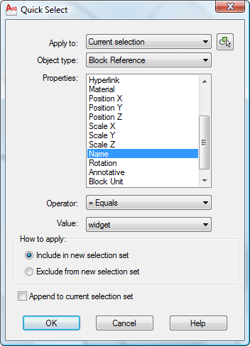
In the Quick Select dialog box, from the Object Type drop-down list, choose Block Reference. If you choose one of the blocks before you start, the Object Type will already be set to Block Reference
From the Properties pane, choose Name.
From the Value drop-down list, choose the name of the block that you want to count.
Click OK to close the Quick Select dialog box.
The Quick Select dialog box
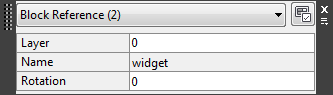
AutoCAD selects all the instances of the block. You can see the number in the Quick Properties panel or the Properties palette.
The Quick Properties panel shows the number of insertions of your block.
Important: While we don't collect cookies, some of our 3rd-party services (such as PayPal and WordPress) do, to give you a safer and better browsing experience. Read about how we use cookies and keep your personal information secure by reading our Privacy Policy here.