A reader recently asked me the following question about AutoCAD 2008:
“When I’m working with xrefs, this comes up a lot: ‘Unreconciled new layer, new layers were found that may need to be reconciled.’ What is this and how do I correct this?”
AutoCAD 2008 introduced layer notification, which is a feature that lets you know when new layers are added to your drawing. Typically, this happens when you attach an xref and the xref’s layers are not already in your drawing.
Layer notification is very useful to help you maintain your standards, but it can also be annoying if you don’t want this feature.
The purpose of layer notification is to help you maintain your layer standards. By default, layer notification applies only when you attach an xref, but you can set it to apply to all layers.
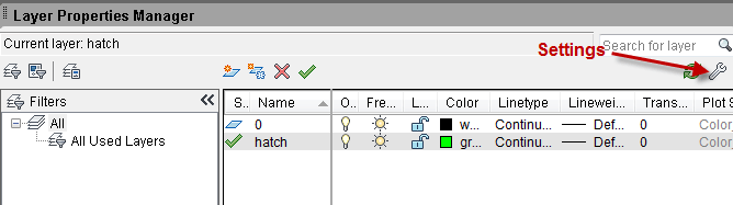
To specify the settings you want for layer notification, open the Layer Properties Manager and click the Settings button.
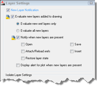
In the Layer Settings dialog box, you can do the following:
Uncheck the New Layer Notification checkbox to turn off layer notification completely. This is controled by the LAYEREVALCTL system variable (0=Off, 1=On)
Click the Evaluate All New Layers option to get a notification any time you add new layers to the drawing, even if not in xrefs. This setting determines which new layers result in notification. This is controlled by the LAYEREVAL system variable (0=Off, 1=xref layers, 2=all layers)
Check the Notifiy When New Layers are Present check box and then choose one or more of the times, such as when you open or save a drawing, or when you attached or reload xrefs. This setting determines when you’ll receive notification. This is controlled by the LAYERNOTIFY system variable.
Check the Display Alert for Plot When New Layers Are Present checkbox to be notified before you plot a drawing that has new layers.
When you’re done, click OK.
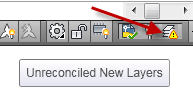
When your drawing meets the conditions you set, you’ll see a notification icon.
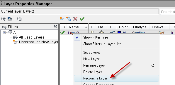
When you see the notification icon, you can click it to open the Layer Properties Manager. You’ll see a layer filter listing unreconciled new layers. If you want to accept the layer, right-click it and choose Reconcile Layer. Otherwise, you can delete the layer, or simply leave it unreconciled.
When you need to draw a rectangle or line that doesn’t start on a geometric point (endpoint, midpoint, etc.) of another object, you might draw a temporary line, called a construction line, from an existing object to the desired start point of the new line.
Then you would draw the rectangle or line. Then erase the construction line.
This is so very 70’s, left over from hand drafting days! Instead you can use another drafting tool to start your new line more quickly and avoid the erasing process. (How many of you have forgotten to erase that line?)
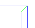
The From object snap
From isn’t really an object snap, but it lets you start lines a certain x,y offset from an existing point. Use it when you know the x and y distances from some point.
Let’s say that you have a rectangle, the outer edge of a window frame, and you want to draw the glass pane as another rectangle inside the first one. You might draw a line 3,2 units from the lower-left corner so that you have an endpoint from which to start your inside pane.
Instead, here’s what you should do:
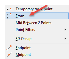
1. Draw the first rectangle. 2. Start the RECTANG command for the second rectangle. 3. At the RECTANG prompt, type from and press Enter. (Or press Shift+right-click and choose From on the Object Snap short-cut menu.) 4. At the Base point: prompt, use an OSNAP to specify the lower-left corner of the first rectangle. 5. At the <Offset>: prompt, enter the offset, such as @3,2. Your rectangle starts in the right place.
IMPORTANT: You must put the @ before the offset, even if you’re using the default relative coordinates.
How do you avoid drawing constructions lines? Leave a comment!
A hyperlink in an AutoCAD drawing can link any drawing object or objects to a URL, any file, or a location in a file (such as a named view in another drawing). If you haven’t been using hyperlinks, consider doing so, as they offer lots of possibilities. Examples of files you can link to are bills of materials, price lists, detail drawings, part specifications, etc.
When you create hyperlinks in your drawing to these other documents, your drawing can become almost like a Web page.
To create a hyperlink, select an object and use the HYPERLINK command. (You can also press Ctrl+K or choose Insert tab> Data panel> Hyperlink.) The Insert Hyperlink dialog box opens.
To link to a file, click the File button, select the file, and click Open. You can also type a URL, or browse to it using the Web Page button.
Now, when you hover the cursor near the object, you see a web cursor.
Using a hyperlink in a drawing is a little different from using one on the Internet. In a drawing, if you click the hyperlink, you just select the object. Duh! There are two ways to open the hyperlink:
Press Ctrl and click, but this doesn’t bring the new file to the fore, so you have to find it on the Windows taskbar
Select the object, right-click and choose Hyperlink> Open. This brings the new file to the fore.
If you send AutoCAD drawings to clients or contractors in electronic form, be sure to send the supporting documents (that you hyperlinked to) electronically as well.
Here are some issues to be aware of:
Hyperlinks aren’t obvious unless you hover the cursor over them. You can add text that says, “Click here for parts specs” and make that text a hyperlink to the document containing the parts specs. For fun, you can underline text to make it look like a hyperlink.
You may need to communicate to the user how to use the hyperlink, that is, press Ctrl+click or select the object, right-click and choose Hyperlink > Open.
Have you used hyperlinks? How did you find them helpful? Do you have any tips for using hyperlinks? Leave an answer in the comments!
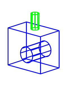
A vector image is an image whose underlying definition is vectors, that is lines, directions, and distances. Programs use equations to define vector images. Many programs create vector images, including Microsoft PowerPoint, Adobe Flash, and, of course, AutoCAD.
Vectors have a great advantage—they never get grainy when you enlarge them; they’re always crisp and clear. On the other hand, you can’t get the subtlety of a photo. Vectors are ideal for diagrams.
The WMF (Windows Metafile) format is a vector image file format. You can export images from AutoCAD in WMF format and import them into PowerPoint, Flash, and other programs that accept WMF images.
To export your drawing, use the EXPORT command. In the Export Data dialog box, expand the Files of Type drop-down list and choose Metafile (*.wmf). Then give the file a name and save it wherever you want it.
What is most wonderful is when you import the image into a program that can ungroup it. Then, you turn the image into native objects that you can edit in that program.
In PowerPoint
Use the Insert>Picture feature to insert the WMF file onto a slide.
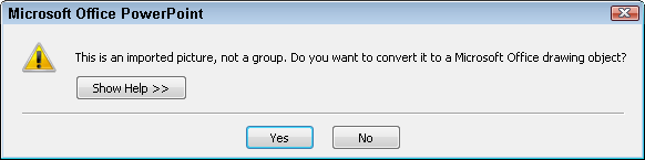
Right-click the selected image and choose Group (or Grouping)> Ungroup. You’ll see a message like this one.
Click Yes.
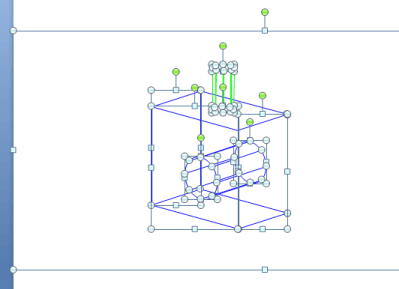
You’re not done yet. Right-click again and ungroup a second time. Now, you’ll see many more objects!
You can almost always delete the large box that surrounds the image.
You can now edit the objects in PowerPoint. Here, I increased the weight (thickness) of the lines.
An object can have a lot of properties and sometimes you want one object to have the same properties as another object. Here are 3 tools that you can use to get the job done quickly.
Match Properties
The MATCHPROP command has been around a long time and lets you easily copy properties from one object to another. Watch it in action.
Match a layer only
If you want to match a layer and nothing else, you can use the LAYERMCH command, which is available in recent releases of AutoCAD and as an Express Tool in earlier releases. Be careful, because it works differently from MATCHPROP. Watch the video.
Create a new object that is like an existing object
A new command for AutoCAD 2011 is the ADDSELECTED command, which creates a new object with the same properties as an existing one. To see how it works, watch the video.
Do you have any other methods of copying properties?
With one exception, you can use the Spacebar instead of the Enter key. It’s often more convenient, because it’s bigger and because if your right hand is on the mouse, you can hit the Spacebar with your left hand. Similarly, you can press the Spacebar at the Command prompt to repeat a command you just used.
The exception is when you’re using a text command, such as MTEXT or TEXT. Pressing the Spacebar, of course, just inserts a space in the text. To end the MTEXT command, you can’t press the Enter key either, because that just inserts a new line in the text. Instead, just click outside the text area or click the Close Text Editor button on the ribbon.
To cycle among Grip editing options
Hein Veeman, a “Technical Draftsman and AutoCAD shortcut freak” in the Netherlands, sent me an e-mail describing how to use the Spacebar to cycle among Grip editing options. Actually, this is just an example of using the Spacebar to replace the Enter key. Here are his steps:
1. Select an object by clicking on it with your mouse.
2. Select a grip point of that object.
You will see the following in the command line:
** STRETCH **
Specify stretch point or [Base point/Copy/Undo/eXit]:
3. Press the Spacebar once more to cycle to the MOVE option.
4. Continue to press the Spacebar to get the Rotate, Scale, and Mirror options.
Select overlapping objects with object cycling
If you have several objects that overlap, you may find it hard to select the one you want. This used to be a real annoyance, because you would select the wrong object, deselect it (by pressing Esc), and try again. In recent releases, AutoCAD highlights objects when you just hover over them, which makes selecting the right object much easier.
Nevertheless, if you’re using an earlier release or have the hover highlighting effect turned off, object cycling can help. (By the way, to customize hover highlighting, start the OPTIONS command. On the Selection tab, click the Visual Effect Settings button. In the Selection Preview Effect section, you can change the settings.)
To use object cycling, at the Select objects: prompt, place the cursor over the area where objects overlap. Then hold down the Shift key and press the Spacebar. One object is highlighted. If it is not the one you want, with the Shift key still down, press the Spacebar again. AutoCAD cycles through the objects. When the object that you want is highlighted, pick the object.
Cycle through faces of a solid
If you want to select the back face of a solid, you can cycle through the faces by pressing and holding Ctrl and repeatedly pressing the Spacebar. Remember that pressing the Ctrl key selects subobjects, such as the face of a solid.
Cycle among gizmos
A fairly new feature allows you to use the Spacebar to cycle among the three gizmos, Move, Rotate, and Scale. The gizmos help you move, rotate, and scale 3D models. Here you see the Rotate gizmo.
You can select an object and the current gizmo appears on the object or you can choose the gizmo you want from the ribbon. You then constrain the direction of the move, rotate or scale operation by clicking one of the colored elements (which correlate to the X, Y, and Z axes.) Once you constrain the move, you can press the Spacebar to cycle among the three gizmos, without losing the directional constraint you specified.
Do you have any other Spacebar shortcuts? Let others know by posting a comment!
Would you like to create a keyboard shortcut to your favorite command-option combination? For example, I would like a version of the COPY command that doesn’t repeat, that is, that ends after one copy operation. Here are the steps:
Enter cui to open the Customize User Interface dialog box.
In the Command List pane, click the New button.
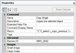
In the Properties pane, you can now specify your new command. Enter a name and a macro. If the macro is long, click the Ellipsis button at the right side of the Macro text box to open the Long String Editor. My macro was^C^C_select;\_copy;_previous;;\\;;
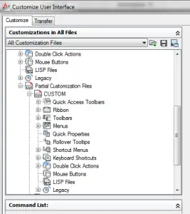
In the Customizations In All Files pane at the top, expand Partial CUI Files, then Custom, then Keyboard Shortcuts, so you can see the Shortcut Keys item.
Check out this free dynamic block tutorial
Plus get free tips in our AutoCAD Tips Newsletter!
Get a free tutorial on creating a complete dynamic block, including a drawing to practice on. You'll make a movable chair, resizable desk, and more. PLUS, the highly-acclaimed AutoCAD Tips Newsletter will keep your skills up to date!
Find your new command in the Command List pane (it’s listed under the name you gave it and a tip is to choose Custom Commands from the drop-down list in that pane) and drag it to the Shortcut Keys item in the top pane.
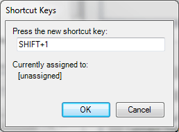
Click the command where it appears in the top pane. Its Properties pane now shows a Key(s) item. Click that item and then click its Ellipsis button. The Shortcut Keys dialog box opens.
Press the shortcut key combination you want to use and you can see if it’s unassigned — or assigned to something you never use. Generally, it has to start with Ctrl, Ctrl+Shift, or Shift. Click OK.
Click OK to close the Customize User Interface dialog box.
Try out your new shortcut!
Note: For information on how to create a custom command, see this tip.
What keyboard shortcuts do you use? Leave a comment! Please also explain what they do, in case it isn’t obvious to everyone.
Recently, a subscriber asked me, “How do I change my screen from white to black?” Many of you know the answer, but I realized that I don’t have this on my website anywhere, so I thought I should add it.
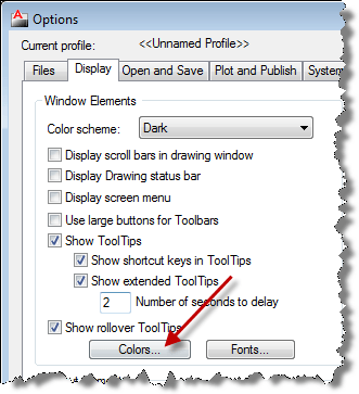
Start the OPTIONS command. An easy way is to right-click anywhere in the drawing area or command line area and choose Options.
Click the Colors button.
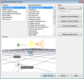
In the Drawing Window Colors dialog box, choose the Context on the left, the Interface element in the middle, and a color from the Color drop-down list. To change the screen color in the 2D Drafting & Annotation workspace, choose 2D Model Space and Uniform Background. This is where most people change the background from white to black or vice versa.
Here are some other color changes you may want to make:
Autosnap Marker. If you change the background color, this may not show up clearly against the new color.
Autotrack Vector. Again, you want to make sure that the color contrasts with the background.
3D background colors. For the 3D Perspective Projection, which you see in the 3D Modeling workspace and when you use the acad3d.dwt (or similar) template, AutoCAD creates a horizon using several colors. You can change the Background Ground Origin element to a light gray and the other related elements still work well. Again, check the Autosnap Marker and Autotrack Vector for good contrast.
There’s a fierce discussion about which is a better background, white (or off white) or black. People feel strongly about this issue. AutoCAD has changed the default background several times recently. What colors do you use?
Dynamic blocks are an amazing feature, but they can be complicated. This tutorial will teach you many techniques that you can use in your own blocks. The door will do the following:
Stretch to 3 sizes
Flip left/right
Flip in/out
This tutorial is updated for AutoCAD 2010 and 2011. Follow these steps:
In a new drawing using architectural units, create a Door layer and make it the current layer.
Draw a rectangle 1-1/2″ x 30″. This is the door.
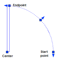
Start the ARC command and use the Center option. Specify the lower-left corner of the door as the center. For the first point, move the cursor to the right at 0°, and type 30 on the command line/dynamic input tooltip. Specify the upper-right corner of the door to draw the arc and complete the swing.
Arc drawing with completed swing
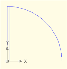
Select both objects, and start the BLOCK command. Call the block Door. Set its base point at the lower-left corner of the door. Check the Open in Block Editor check box. Click OK. The door opens in the Block Editor with its base point at the 0,0 point of the axes.
Block door drawing
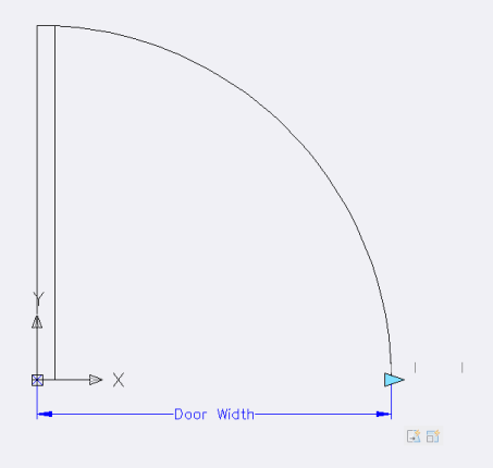
From the Parameters tab of the Block Authoring palettes, choose Linear Parameter. At the prompt, pick the lower-left corner of the door and then the start point of the arc on the right. If prompted, pick a point below the door for the label.
Block door label
Note: The exclamation point indicates that the process is incomplete or incorrect. You almost always see the exclamation point when you place a parameter, because most parameters need an action.
Select the parameter, right-click it, and choose Grip Display> 1. This removes the left grip, which is important because you’ll be stretching from the right grip only. If you don’t do this step, the exclamation point won’t go away when you add the action.
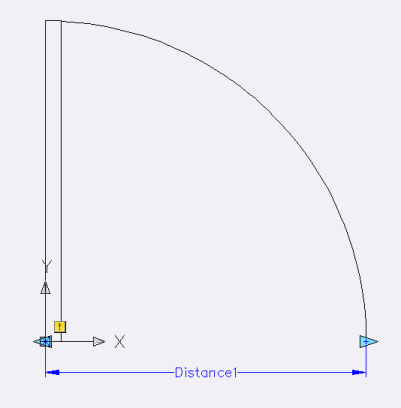
With the parameter still selected, open the Properties palette. In the Property Labels section, click the Distance Name item and change the value to Door width.
From the Actions tab of the Block Authoring Palettes, choose Stretch Action. At the prompt, select the linear parameter.
At the Specify parameter point to associate with action or enter [sTart point/Second point] <Start>: prompt, click the right grip (the turquoise triangle).
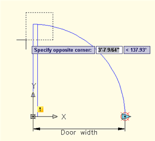
At the Specify first corner of stretch frame or [CPolygon]: prompt, pick a point above and to the right of the door. At the Specify opposite corner: prompt, pick a point to the left of the door and down, as you see here.
Specify door corners
At the Select objects: prompt, pick the door (the rectangle), but nothing else. End selection.
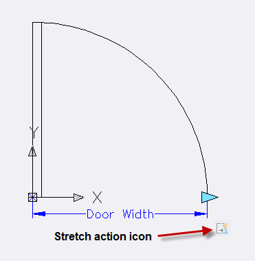
At the Specify action location or [Multiplier/Offset]: prompt, right-click and choose the Offset option. This option lets you change the angle of the stretch action. At the Enter angle offset <0.00>: prompt, enter 90. (In earlier releases, you’ll be prompted for an action location. Pick a point to the right of the grip.) In newer releases, the command ends, placing a small action icon automatically.
Select the action icon and open the Properties palette. It’s sometimes hard to select the action icon, so check that Stretch Action displays at the top of the Properties palette. In the Overrides section, change the Angle Offset value to 90. As you stretch to the right, the door will stretch upward.
Stretch action
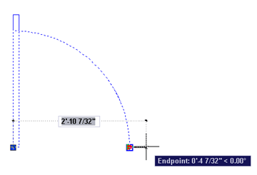
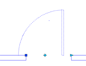
Before going any further, click the Save Block button on the Block Editor’s toolbar/tab and click the Close Block Editor button. It’s a good practice to test your dynamic block at each stage. In AutoCAD 2010 or later, you can test by clicking Test Block.
Save your drawing, too. Select the door, click the Stretch grip on the right and drag to the right. The door should stretch in the 90° direction, as you see here. Of course, the arc doesn’t do anything, but we’ll fix that later.
Door stretch 90° direction
In order to constrain the width of the door to common widths, select the door and open the Block Editor again or close the Test Block window.
Select the linear parameter. In the Properties palette, scroll down to the Value Set section.
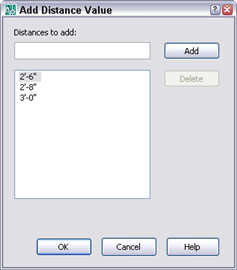
Click the Dist Type item and choose List from the drop-down list. Click the Dist Value List item and click the Ellipsis button. Enter 32 in the Distance to Add box and press Enter. Then enter 36 and press Enter. Then click OK. You now see thin, vertical bars to the right of the door to indicate the allowable door widths.
Adding distance value
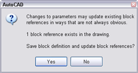
Save the block again and close the Block Editor. You may see this dialog box or a similar one now or later in this tutorial. Sometimes, saving changes to a block that’s already in your drawing can cause problems, but usually it’s all right. So click Yes.
Save block changes
Try stretching the door this time. You’ll see those vertical bars again and you’ll be able to stretch only to those distances.
Now it’s time to get that arc to follow the door. You might think that you could stretch the arc, too, but stretched arcs become distorted. Instead, you want to scale the arc. Because you want the arc to stretch by the same amount that you stretch the door, you use the same parameter and add another action to it, this time a Scale action. So, open the Door block in the Block Editor again.
On the Actions tab, choose Scale Action. At the Select parameter: prompt, select the linear parameter. At the Select objects: prompt, select the arc and end selection. For earlier releases, at the Specify action location or [Base type]: prompt, place the action label near the arc.
Arc action label
Save and test. As you stretch the door, the arc scales accordingly. Make sure that there are no gaps at any width. If there are, you need to correct something.
It would be great to create a door that can flip in all directions because this could replace four separate blocks or remove the necessity to insert a door block at negative values. To do this, return to the Block Editor.
From the Parameters tab, choose Flip. At the Specify base point of reflection line or [Name/Label/Description/Palette]: prompt, Shift+right-click and choose Mid Between Two Points. Then specify the endpoint at the basepoint of the block and the endpoint at the start point of the arc. At the Specify endpoint of reflection line: prompt, move up 90° and pick. (The length of the reflection line is not important.) At the Specify label location: prompt, pick a location inside the arc.
From the Actions tab, choose Flip. At the Select parameter: prompt, choose the Flip parameter. At the Select objects: prompt, select the door and its arc. If prompted to do so, place the label next to the Flip parameter.
Save the block and test .Select the block. Click the flip grip and the door flips. Flip it back again. Now try stretching the door to its maximum width and flip again. There are two problems:
The stretch grip stays on the right when you flip the door, so now you can’t stretch the door.
Did you notice that the flip grip stays where it was? It’s no longer in the middle of the door, which means that it won’t flip properly. If you draw two walls with a 3’ gap and flip the door, you’ll see this clearly.
Note: You can see why you need to test dynamic blocks thoroughly!
Test dynamic blocks
To make the stretch grip flip, you need to include it in the selection set of the flip action. In fact, you need to include the linear parameter, the stretch action, and the arc’s scale action so that everything works no matter which way the door is flipped. So, open the door in the Block Editor again.
Select the flip action icon (not the flip parameter). Right-click it and choose Action Selection Set> New Selection Set. At the Select object to add to action set or [Remove]: prompt, type all and press Enter to end selection.
Save the block and exit the Block Editor. Start by stretching the door back to its minimum of 30″. Flip the door a couple of times and you’ll see that the stretch grip flips back and forth at all widths. The arc works properly, too.
To fix the problem with the flip grip not staying at the midpoint, you need to move it when you stretch the door. In fact, you need to move it half the distance that you stretch. This will keep the flip grip centered. Open the door in the Block Editor again.
From the Actions tab, choose Move. At the Select parameter: prompt, select the linear parameter, because you want the flip parameter to move in concert with (but half the distance of) that parameter. At the Specify parameter point to associate with action or enter [sTart point/Second point] <Start>: prompt, pick the right grip on the linear parameter. At the Select objects: prompt, select the flip parameter (not the action). End selection. Select the Move action icon and open the Properties palette. Set the Distance Multiplier option to .5. If prompted, place the move label near the flip parameter.
Save and test the door at the 3 widths. Now, when you stretch the door, after you click, the flip grip jumps to the new midpoint of the door.
Actually, there’s another problem! You don’t see it unless you do the following. Start with the door opening to the right (its original direction) and stretch it to its maximum width, 3’. Flip it. Then stretch it to its narrowest width. Do you see how the block’s insertion point doesn’t move with the block? This makes moving the block difficult. So open the door for editing again.
From the Parameters tab, choose Base Point. At the prompt, specify the bottom-left corner of the door, which is 0,0 in the Block Editor. You can use the Endpoint object snap to specify the point.
Now, select the flip action, right-click, and choose Action Selection Set> Modify Selection Set. At the Select object to add to action set or [Remove]: prompt, select the new base point parameter and press Enter to end selection.
Save and test the block again as you did before (it may have moved — if so, move it back). You’ll see that the block’s base point always stays on the block.
There’s just one more procedure—to add a flip action going the other way, so that the door can open inward or outward. So open the door for editing again.
Choose Flip from the Parameter tab and start the reflection line at the lower-left corner of the door — the basepoint. End this horizontal reflection line at the bottom endpint of the arc. Place the label to the left of the door.
On the Actions tab, choose Flip Action. At the Select parameter: prompt, choose the flip parameter. At the Select objects: prompt, type all and end selection. (That’s what you learned you needed to do in the previous steps.) You should see 13 found. If prompted for a location, place the label beneath the flip parameter label.
Save and test the door.
You probably thought you were done, but there’s one more step. As you did before, stretch the door to its maximum width. Flip the door to the left and then stretch it to its narrowest. You’ll see that the new flip grip doesn’t follow. That’s because it isn’t included in the first flip action you created. (It couldn’t be, because the new flip action didn’t exist then.) In fact, you want the in/out flip parameter to flip with the left/right flip action.
Re-edit the block. Select the first flip action, right-click and choose Action Selection Set> Modify Selection Set. At the Select object to add to action set or [Remove]: prompt, select the new flip parameter. Save, exit, and test again.
As you can see, there is often an iterative process, requiring you to go back and include new objects in actions that you created earlier. Remember to thoroughly test your dynamic blocks!
Important: While we don't collect cookies, some of our 3rd-party services (such as PayPal and WordPress) do, to give you a safer and better browsing experience. Read about how we use cookies and keep your personal information secure by reading our Privacy Policy here.