
Dynamic blocks are an amazing feature, but they can be complicated. This tutorial will teach you many techniques that you can use in your own blocks. The door will do the following:
- Stretch to 3 sizes
- Flip left/right
- Flip in/out
This tutorial is updated for AutoCAD 2010 and 2011. Follow these steps:
- In a new drawing using architectural units, create a Door layer and make it the current layer.
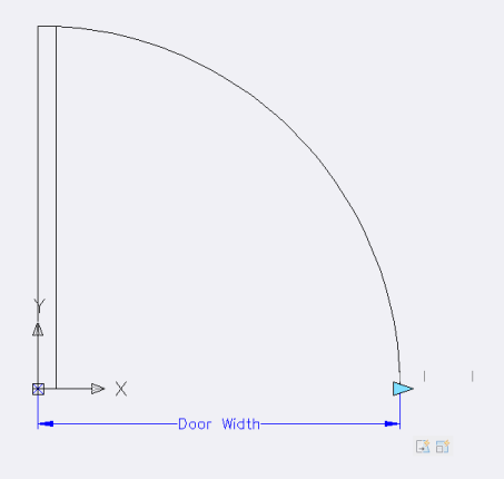
- Draw a rectangle 1-1/2″ x 30″. This is the door.
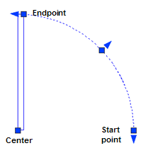
- Start the ARC command and use the Center option. Specify the lower-left corner of the door as the center. For the first point, move the cursor to the right at 0°, and type 30 on the command line/dynamic input tooltip. Specify the upper-right corner of the door to draw the arc and complete the swing.
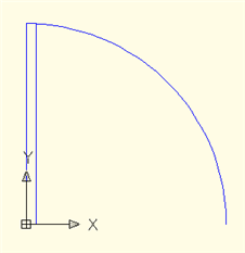
Arc drawing with completed swing
- Select both objects, and start the BLOCK command. Call the block Door. Set its base point at the lower-left corner of the door. Check the Open in Block Editor check box. Click OK. The door opens in the Block Editor with its base point at the 0,0 point of the axes.
Block door drawing
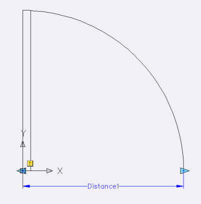
- From the Parameters tab of the Block Authoring palettes, choose Linear Parameter. At the prompt, pick the lower-left corner of the door and then the start point of the arc on the right. If prompted, pick a point below the door for the label.
Block door label
Note: The exclamation point indicates that the process is incomplete or incorrect. You almost always see the exclamation point when you place a parameter, because most parameters need an action.
- Select the parameter, right-click it, and choose Grip Display> 1. This removes the left grip, which is important because you’ll be stretching from the right grip only. If you don’t do this step, the exclamation point won’t go away when you add the action.
- With the parameter still selected, open the Properties palette. In the Property Labels section, click the Distance Name item and change the value to Door width.
- From the Actions tab of the Block Authoring Palettes, choose Stretch Action. At the prompt, select the linear parameter.
- At the Specify parameter point to associate with action or enter [sTart point/Second point] <Start>: prompt, click the right grip (the turquoise triangle).
- At the Specify first corner of stretch frame or [CPolygon]: prompt, pick a point above and to the right of the door. At the Specify opposite corner: prompt, pick a point to the left of the door and down, as you see here.
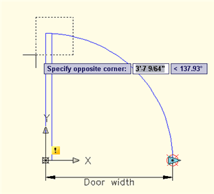
Specify door corners
- At the Select objects: prompt, pick the door (the rectangle), but nothing else. End selection.
- At the Specify action location or [Multiplier/Offset]: prompt, right-click and choose the Offset option. This option lets you change the angle of the stretch action. At the Enter angle offset <0.00>: prompt, enter 90. (In earlier releases, you’ll be prompted for an action location. Pick a point to the right of the grip.) In newer releases, the command ends, placing a small action icon automatically.
- Select the action icon and open the Properties palette. It’s sometimes hard to select the action icon, so check that Stretch Action displays at the top of the Properties palette. In the Overrides section, change the Angle Offset value to 90. As you stretch to the right, the door will stretch upward.
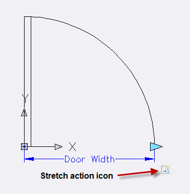
Stretch action
- Before going any further, click the Save Block button on the Block Editor’s toolbar/tab and click the Close Block Editor button. It’s a good practice to test your dynamic block at each stage. In AutoCAD 2010 or later, you can test by clicking Test Block.
- Save your drawing, too. Select the door, click the Stretch grip on the right and drag to the right. The door should stretch in the 90° direction, as you see here. Of course, the arc doesn’t do anything, but we’ll fix that later.
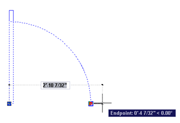
Door stretch 90° direction
- In order to constrain the width of the door to common widths, select the door and open the Block Editor again or close the Test Block window.
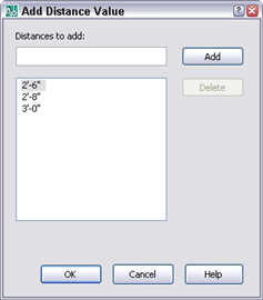
Adding distance value
- Save the block again and close the Block Editor. You may see this dialog box or a similar one now or later in this tutorial. Sometimes, saving changes to a block that’s already in your drawing can cause problems, but usually it’s all right. So click Yes.
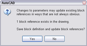
Save block changes
- Try stretching the door this time. You’ll see those vertical bars again and you’ll be able to stretch only to those distances.
- Now it’s time to get that arc to follow the door. You might think that you could stretch the arc, too, but stretched arcs become distorted. Instead, you want to scale the arc. Because you want the arc to stretch by the same amount that you stretch the door, you use the same parameter and add another action to it, this time a Scale action. So, open the Door block in the Block Editor again.
- On the Actions tab, choose Scale Action. At the Select parameter: prompt, select the linear parameter. At the Select objects: prompt, select the arc and end selection. For earlier releases, at the Specify action location or [Base type]: prompt, place the action label near the arc.
Arc action label
- Save and test. As you stretch the door, the arc scales accordingly. Make sure that there are no gaps at any width. If there are, you need to correct something.
- It would be great to create a door that can flip in all directions because this could replace four separate blocks or remove the necessity to insert a door block at negative values. To do this, return to the Block Editor.
- From the Parameters tab, choose Flip. At the Specify base point of reflection line or [Name/Label/Description/Palette]: prompt, Shift+right-click and choose Mid Between Two Points. Then specify the endpoint at the basepoint of the block and the endpoint at the start point of the arc. At the Specify endpoint of reflection line: prompt, move up 90° and pick. (The length of the reflection line is not important.) At the Specify label location: prompt, pick a location inside the arc.
- From the Actions tab, choose Flip. At the Select parameter: prompt, choose the Flip parameter. At the Select objects: prompt, select the door and its arc. If prompted to do so, place the label next to the Flip parameter.
- Save the block and test .Select the block. Click the flip grip and the door flips. Flip it back again. Now try stretching the door to its maximum width and flip again. There are two problems:
- The stretch grip stays on the right when you flip the door, so now you can’t stretch the door.
- Did you notice that the flip grip stays where it was? It’s no longer in the middle of the door, which means that it won’t flip properly. If you draw two walls with a 3’ gap and flip the door, you’ll see this clearly.
Note: You can see why you need to test dynamic blocks thoroughly!
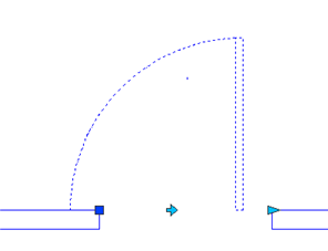
Test dynamic blocks
- To make the stretch grip flip, you need to include it in the selection set of the flip action. In fact, you need to include the linear parameter, the stretch action, and the arc’s scale action so that everything works no matter which way the door is flipped. So, open the door in the Block Editor again.
- Select the flip action icon (not the flip parameter). Right-click it and choose Action Selection Set> New Selection Set. At the Select object to add to action set or [Remove]: prompt, type all and press Enter to end selection.
- Save the block and exit the Block Editor. Start by stretching the door back to its minimum of 30″. Flip the door a couple of times and you’ll see that the stretch grip flips back and forth at all widths. The arc works properly, too.
- To fix the problem with the flip grip not staying at the midpoint, you need to move it when you stretch the door. In fact, you need to move it half the distance that you stretch. This will keep the flip grip centered. Open the door in the Block Editor again.
- From the Actions tab, choose Move. At the Select parameter: prompt, select the linear parameter, because you want the flip parameter to move in concert with (but half the distance of) that parameter. At the Specify parameter point to associate with action or enter [sTart point/Second point] <Start>: prompt, pick the right grip on the linear parameter. At the Select objects: prompt, select the flip parameter (not the action). End selection. Select the Move action icon and open the Properties palette. Set the Distance Multiplier option to .5. If prompted, place the move label near the flip parameter.
- Save and test the door at the 3 widths. Now, when you stretch the door, after you click, the flip grip jumps to the new midpoint of the door.
- Actually, there’s another problem! You don’t see it unless you do the following. Start with the door opening to the right (its original direction) and stretch it to its maximum width, 3’. Flip it. Then stretch it to its narrowest width. Do you see how the block’s insertion point doesn’t move with the block? This makes moving the block difficult. So open the door for editing again.
- From the Parameters tab, choose Base Point. At the prompt, specify the bottom-left corner of the door, which is 0,0 in the Block Editor. You can use the Endpoint object snap to specify the point.
- Now, select the flip action, right-click, and choose Action Selection Set> Modify Selection Set. At the Select object to add to action set or [Remove]: prompt, select the new base point parameter and press Enter to end selection.
- Save and test the block again as you did before (it may have moved — if so, move it back). You’ll see that the block’s base point always stays on the block.
- There’s just one more procedure—to add a flip action going the other way, so that the door can open inward or outward. So open the door for editing again.
- Choose Flip from the Parameter tab and start the reflection line at the lower-left corner of the door — the basepoint. End this horizontal reflection line at the bottom endpint of the arc. Place the label to the left of the door.
- On the Actions tab, choose Flip Action. At the Select parameter: prompt, choose the flip parameter. At the Select objects: prompt, type all and end selection. (That’s what you learned you needed to do in the previous steps.) You should see 13 found. If prompted for a location, place the label beneath the flip parameter label.
- Save and test the door.
- You probably thought you were done, but there’s one more step. As you did before, stretch the door to its maximum width. Flip the door to the left and then stretch it to its narrowest. You’ll see that the new flip grip doesn’t follow. That’s because it isn’t included in the first flip action you created. (It couldn’t be, because the new flip action didn’t exist then.) In fact, you want the in/out flip parameter to flip with the left/right flip action.
- Re-edit the block. Select the first flip action, right-click and choose Action Selection Set> Modify Selection Set. At the Select object to add to action set or [Remove]: prompt, select the new flip parameter. Save, exit, and test again.
As you can see, there is often an iterative process, requiring you to go back and include new objects in actions that you created earlier. Remember to thoroughly test your dynamic blocks!
Watch the video of how the door functions.
Thanks to Edwin Prakoso for helping me debug this block. He suggested typing “all” to select objects.
Related tips

- Combine or subtract 2D shapes to create custom shapes - February 17, 2022
- Working with linetype scales - January 18, 2022
- Rename named objects–blocks, dimension styles, layers, and more - December 21, 2021


Ellen
(1)End point of the arc should be upper-left corner of the door frame. Otherwise there is a gap with large width doors. This is because eventhough we selected the point the arc will not end with that point in any center method. Otherwise draw the arc with any other method or move the arc end point to the upper-right corner at the beginning.
(2) As you said under step 39, if the start point of the reflection line located at the basepoint, no existence of basepoint grip in the block which creates problem to move or move/copy the inserted dynamic block using grip method.
(3) Provide description for the parameters which gives tooltip.
(4) Save the block using Wblock or else otherwise the Design Center is the only path to insert the block.
It is my opinion that:
(i) the flip inward/outward can be started with mid point between the basepoint and the arc start point.
(ii) the flip left/right can be started 6″ below the mid point between the basepoint and the arc start point.
It is also my opinion other than learning purpose that:
(i) Parameter Sets (LinearStretch) can be used for Linear parameter and stretch action.
(ii) Basepoint parameter can be set before flip parameters.
(iii) First set flip in/out parameter and then set flip left/right parameter.
(iv) After setting both flip parameters flip actions can be set using selection method “all”.
(v) Set move action for both flip parametes with multiplier option of 0.5.
Excellent resource!! Thanks for the info. One more parameter/action you might want to incorporate in this dynamic door is Rotate. Upon insertion of the block, it will automatically allow you to rotate it into place. This is a great feature for walls that aren’t square (on the X or Y axis).
Since I added it into mine, here’s what I did:
44. From the parameters tab, select “Rotation Parameter”, then pick the bottom-left corner of your door (the base point). At the “Specify radius of parameter:” prompt, pick a point on the +Y-axis. Any point will do. At the “Specify default rotation angle or [Base angle] :” prompt, type in 90 (or pick a point anywhere on the +Y-axis. And at the “Specify label location:” prompt, pick a point some distance away from your “Flip Grip” so that you can see both grips at a distance (when zoomed out).
45. Now, from the Actions Tab, select “Rotate Action” then select the Angle1 parameter. At the “Select Object:” prompt, select ALL. Then specify a location for the action label and you’re done.
46. Now go test the new rotate feature of your door.
47. Oops. One last thing. Go back to your original Flip action and add the new Rotate Parameter to your Selection Set.
48. One last test and you’re done. 🙂
Hi
Re: Create a Dynamic Block of a door
I am using AutoCAD 2010. I follow your procedure but only up to ’11’. The session end there, no ‘Specify action location’ prompt follows but the Stretch action icon appears as in the diagram below ’13’.
I saved the block nevertheless but when do Test Block it doesn’t work.
Can you help me out please?
Excellent resource!! Thanks for the info. One more parameter/action you might want to incorporate in this dynamic door is Rotate. Upon insertion of the block, it will automatically allow you to rotate it into place. This is a great feature for walls that aren’t square (on the X or Y axis).
Since I added it into mine, here’s what I did:
44. From the parameters tab, select “Rotation Parameter”, then pick the bottom-left corner of your door (the base point). At the “Specify radius of parameter:” prompt, pick a point on the +Y-axis. Any point will do. At the “Specify default rotation angle or [Base angle] :” prompt, type in 90 (or pick a point anywhere on the +Y-axis. And at the “Specify label location:” prompt, pick a point some distance away from your “Flip Grip” so that you can see both grips at a distance (when zoomed out).
45. Now, from the Actions Tab, select “Rotate Action” then select the Angle1 parameter. At the “Select Object:” prompt, select ALL. Then specify a location for the action label and you’re done.
46. Now go test the new rotate feature of your door.
47. Oops. One last thing. Go back to your original Flip action and add the new Rotate Parameter to your Selection Set.
48. One last test and you’re done. 🙂
why don’t you make a video with the process???
“Specify action location or [Multiplier/Offset]: ” doesn’t appear.
I just get until the step 11.
The exact prompts change sometimes with a new release. That’s what happened in this case. Sorry, but I can’t manage to update all the tips each year…
I DID IT ALL AND FOUND 2 PROBLEMS: THE CENTER OF THE ARC DOESNT STAY IN THE CORNER OF THE DOOR, AND WHEN FLIPPING THE DOOR, THE STRETCH OF THE LEAF IS INVERSE TO THE STRETCH OF THE OPENING, I MEAN: IF STRETCHING TO A GREATER MEASURE THE LEAF GETS SHORTER. HOW CAN I FIX THIS?
useful tutorial…But quite complicated to do.. please provide a video tutorial..
I thought it was great. Thanks for taking the time to post this!
Hi,
Great link which has helped a lot. It could REALLY do with a LOT more illustrations / screen shots to help people understand the instructions more clearly – especially those no very familiar with AutoCAD.
I’ve used AutoCAD a little bit – and it even took me a few ‘goes’ to understand exactly which way to set thngs up. A great example is….
Instructions from #24 onwards are very vague. I cannot get the flip to work? Probably got to do with comments like: “endpoint at the start point” etc. When I get to the end of #25 I have another yellow exclamation mark on the flip parameter? AutoCAD says this is because there are no actions associated with this parameter?
Hence why a lot more clarity would help.
Thanks.
hello, thanks for this very useful post.
Very good instruction set. You explained why you were doing things very well.
I did find when typing “all”, that it returned “15 found, 2 not in current space”. I was working inside an existing drawing, so I am a bit mystified what those other two objects were.
Thanks for making this tutorial.
The 2 objects not in current space would probably be viewports in paper space.
I followed all the steps with acad2008 and it worked perfectly. Never used dynamic blocks before so this was an excellent tutorial although its still relatively difficult I think and there are a lot of other paramters and actions to play with. Thanx!
helloo…..
when i select one line than above selected line will be deselcet. so how can i solve this problem…..
thanks……
If this happens with all objects — that is, when you select a 2nd object, the 1st is deselected, it’s a setting in the Options dialog box (OPTIONS command). Click the Selection tab and uncheck Use Shift to Add to Selection.
how can i make door & window in wall?
I just wrote a tutorial on breaking a wall for a door. https://allaboutcad.com/how-to-break-walls-to-insert-a-door/
Dear Ellen. Good tutorial, but i’ve a problem. When i flip the door, and then i stretch it, the door panel stretching inverse. how i can resolve this problem ?
Thanks Ellen!
This is a very useful tutorial. I have been creating the same dynamic block as you have, and wish I would have found this website hours ago. I am having the same problem as some other users, when I flip the block, then stretch it, the leaf stretches in the wrong direction. I believe this has something to do with the fact that it is set to stretch 90 degrees relative to the stretch point, but since we are flipped, it is now stretching -90 degrees. Has anyone figured out a solution to this.
Thanks, Kyle
Filippo,
When you set up your flip command, manually type ‘all’ for your selection into the command line, instead of using your mouse to select the objects.
Hi this block works great except for when I stretch it the arc scales away from the doorstep the top. Do you know why this would be? I’ve tried making it again and playing with options I know but still get nothing.
hi ellen, I can’t get to the “Specify action location” prompt.
I select my object, and then I apparently do not know how to “end selection” properly.
I select it, hit return ?) and then…. no more prompts.
Very frustrating.
Hi Ellen,
Thanks for the information. I found this useful and it has relieved me of many headaches.
Was struggling with this for one or so hours. I am happy to have stumbled across this page.
Cheers.
Thanks for this it was really helpful. The second flip axis is a bit superfluous as a door can only be either clockwise or anticlockwise opening, there are no other possibilities for a normal hinged door, and the block can be easily rotated. I added an alignment parameter to align the block with the wall and this also has the effect of rotating the block depending which side of the line you align to.