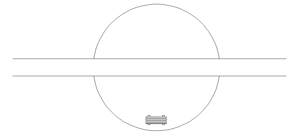
Instead of creating a polar array, in some situations, you can use the ROTATE command’s Copy option. It works best when you want to end up with 2 or 3 objects, because you need to repeat the ROTATE command for each copy.
For example, let’s say that I want to add 2 more benches around the inner edge of the circle (which is actually two arcs), at 30 degree intervals.
Here are the steps:
Select the bench. (It’s a block, so it’s one object.)
Start the ROTATE command.
At the Specify base point: prompt, specify the Center object snap of the arc.
At the Specify rotation angle or [Copy/Reference] <90>: prompt, specify the Copy option.
When the Specify rotation angle or [Copy/Reference] <90>: prompt repeats, specify 30 to create the new bench.
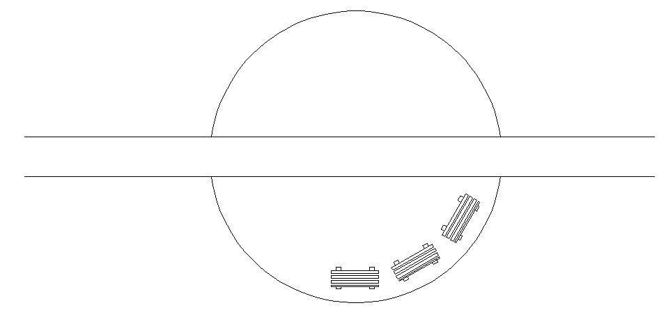
Press Enter to repeat the ROTATE command.
At the Select objects: command, select the second bench and press Enter to end selection.
At the Specify base point: prompt, again specify the Center object snap of the arc.
At the Specify rotation angle or [Copy/Reference] <30>: prompt, again specify the Copy option. Notice that the command remembered the 30 degree rotation.
Press Enter to rotate and copy the second bench.
Here’s the result:
How do you use the Copy option of the ROTATE command?
You can align a rectangle with a line or other existing object on the fly, avoiding the need for a separate rotation. Watch the video or read the steps.
Here are the steps:
Start the RECTANG command.
At the Specify first corner point or [Chamfer/Elevation/Fillet/Thickness/Width]: prompt, specify the first point.
Choose the Rotation option.
Choose the Pick Points option
Specify the endpoints of the line that you want to align the rectangle to.
At the Specify other corner point or [Area/Dimensions/Rotation]: prompt, specify the second corner point to complete the rectangle.
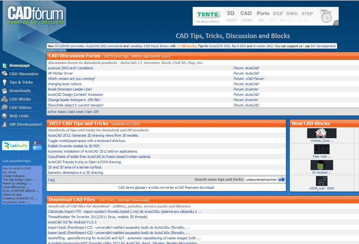
I want to introduce you to a great resource: CADstudio and CADforum.
CADstudio is a free multi-language CAD portal (the link is to the English section) supporting CAD and GIS users, especially users of Autodesk products – both professionals and students, from all over the world. It offers offers thousands of practical tips and tricks, hundreds of free add-on utilities and tools, CAD videos, a complete database of AutoCAD commands in multiple languages, online conversion tools, and a huge block library with thousands of CAD symbols, dynamic blocks and 3D models (DWG, RFA, IPT) uploaded by the users. CAD Studio is an Autodesk Gold Partner based in the Czech Republic. The website has been running since 2000.
CADforum is a free forum where you can ask questions and get answers. You’ll find a discussion forum with 90.000 postings and about 190.000 registered users. Register (and then log in) at the upper-right corner to gain access to all the features and content.
The two sites are intertwined. For example, from the forum, you can easily find links to the tips. Most of the content is in Czech and Slovak but the most popular part is in English.
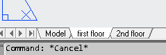
When you’re ready to lay out your drawing for plotting, you’ll start working with layout tabs. Here are some tips to make this task easier.
Rename a layout tab by double-clicking it, then just type the new name and press Enter. And remember, you should name your layouts something other than Layout1, Layout2, etc.
Move a layout tab by dragging it to a new location. To copy, press Ctrl and drag. Then rename it.
To move through the layouts from left to right, press Ctrl+Page Down. From right to left, Ctrl + Page Up. This doesn’t cycle around, so when you get to the end, you have to go the other way.
Right-click a layout tab to do the following:
Create a new layout
Create a layout from a template. The Select File dialog box opens. Choose a DWG, DXF or DWT file and click Open. AutoCAD imports everything on that layout, including viewports, existing text, the titleblock, etc.
Delete a layout
Rename a layout
Recent releases let you hide the tabs (one release, I don’t remember which one, even had this as the default). I don’t recommend it because you lose the ability to use some of these tips. If you don’t see tabs, right-click the button next to the MODEL/PAPER button on the taskbar and choose Display Layout and Model Tabs.
What are your favorite tips for working with layout tabs? Leave a comment!
The DIMEDIT command lets you move or rotate dimension text, change text, and create oblique (angled) extension lines. You type it on the command line. You see the following prompt:
Enter type of dimension editing [Home/New/Rotate/Oblique] <Home>:
You would use it only in certain situations.
Clean up dimension text location
If the text was moved, usually with grips, use the Home option to return the text’s placement to the setting specified by its dimension style. Select the dimensions you want to fix and press Enter to end selection. This makes DIMEDIT a good clean-up tool for sloppy dimensions!
Change or add to existing dimension text
If you want to change the dimension’s text, follow these steps:
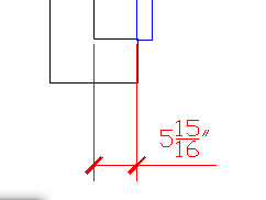
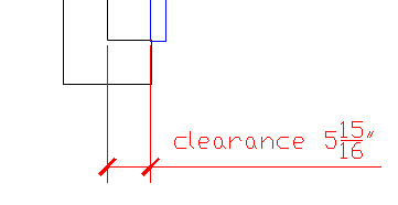
Use the New option. The Text Editor appears and you see selected text (brackets or 0). This represents the existing text. The reason you see it this way is that you can use DIMEDIT to edit the text on multiple dimensions at once.
To replace the existing text, delete the selected text and type new text. To add text to the existing text, use the arrow keys to move to the left or right and type the text. Then click OK or Close Text Editor.
At the Select objects: prompt, select the dimensions that you want to edit, then press Enter to end selection.
This use of DIMEDIT makes it good for changing many dimensions at once! Here you see I’ve added the word “clearance” before the existing text.
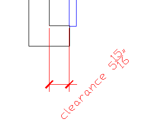
Rotate dimension text
This option works like rotating any text. You would probably only use it when you need to squeeze the text into a small space. Can you think of a good use for this? Use the Rotate option and specify the rotation angle. Here, it’s 45 degrees. Then select objects.
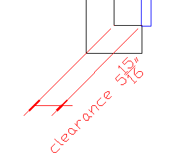
Rotate the dimension extension lines
This creates oblique extension lines and would also be used when you’re trying to squeeze dimensions into a small space. Use the Oblique option, specify the obliquing angle, which is the final angle, not the amount of rotation, and select objects. Here you see a 45-degree obliquing angle.
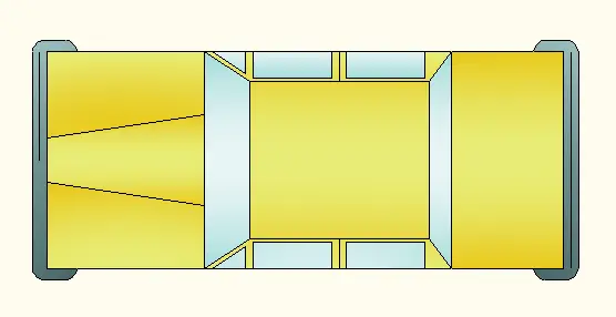
Gradients are a great way to easily make a 2D drawing look like a presentation drawing done in Photoshop or Illustrator. AutoCAD offers one- or two-color gradients and lots of variations.
Here are the steps to create a gradient:
Start the HATCH command. Depending on the release of AutoCAD, the Hatch and Gradient dialog box opens with the Gradient tab on top or the Hatch Creation tab opens. If you see the ribbon, choose Gradient from the Hatch Type drop-down in the Properties panel.
Choose your colors:
In the dialog box, choose One Color or Two Color. If you choose One Color, click the ellipsis button to choose a color and click OK. Then use the slider on the right to adjust the Shade/Tint slide. This lets you create a gradient that gradates to black or white. If you choose Two Color, select the second color in the same way that you chose the first one.
On the ribbon, click the Gradient Colors button in the Properties panel to toggle 1 or 2 colors. Then, choose a color from the color drop-down lists.
Choose one of the 9 gradient types from the dialog box or the Pattern panel on the ribbon.
By default, the gradients are centered. You can uncenter them by unchecking the Centered check box or button. You’ll see the center in the 9 thumbnails move.
You can change the angle of the gradient using the Angle drop-down list or slider. Again, watch the thumbnails to see the results.
To let AutoCAD calculate a closed area, choose the (Add) Pick Points button. To select a closed object, click the Add Select Objects or Select button. In the drawing, either click inside a closed area or select an object, depending on the method you chose.
If you’re using the dialog box, right-click and choose Preview from the shortcut menu. Right-click to accept the hatch. Press Enter or Esc to return to the dialog box. Otherwise, you see a preview immediately; press Enter or OK to end the command.
There are several ways to export a drawing to a PDF file–I have links to some other related tips below. But most don’t have a way for you to specify your scale, because they aren’t connected to the plotting process.
Instead, you can plot to a PC3 file that creates a PDF file. This method gives you the opportunity to specify your scale.
Follow these steps:
Set up your viewport to the scale you want.
With the viewport’s layout tab still displayed, choose Output tab> Plot.
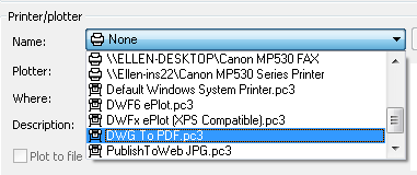
In the Plot dialog box, from the Printer/Plotter drop-down list, choose DWG To PDF.pc3.
From the Paper Size drop-down, choose the paper size you want.
Specify any other settings you want.
Click OK.
AutoCAD opens the Browse for Plot File dialog box, where you can specify the PDF file’s name and location.
Click Save.
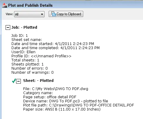
Your drawing goes through the plotting process and you’ll see the Plot Notification balloon at the lower-right corner. You can click the balloon’s link to see the Plot and Publish Details window.
Saving your layout setup
You can create a plot setup with these settings. Then you can apply that setup any time you want to output a PDF file for a layout. Follow these steps:
Right-click the layout tab and choose Page Setup Manager.
Click New, name the setup and click OK.
In the Page Setup Manager dialog box, specify your settings as you would in the Plot dialog box.
Click OK.
When you’re ready to plot, open the Plot dialog box. From the Plot Setup drop-down list, choose your plot setup.
Several of the students have Macs and they downloaded the new Mac version of AutoCAD. It doesn’t have a ribbon; instead, it looks like the Classic AutoCAD workspace—you know, menu and toolbars.
I started teaching at the beginning of this week—just my luck to start teaching the during week that Autodesk introduced the new 2012 release of AutoCAD. So, some students have AutoCAD 2012. (We’re up to 3 different releases now!)
Finally, as I was teaching, I realized that some of these students will go out into the workplace and work on—well, who knows which release will be used where they work?
Do you work in a place that has multiple versions of AutoCAD? Or do you train people using different versions? How do you provide information about how to use AutoCAD in this situation?
As a result, I’m placing a lot of emphasis on command names and aliases—command shortcuts. Aliases are pretty universal and the students like them. We have a little game, almost. I say the command name and say, “So what’s the alias for that?” They quickly try a couple of combinations and tell me. Then I announce it to the class. Aliases are a very quick way to execute commands in AutoCAD.
Do you use mostly aliases? Are you a typer of command names and aliases or do you click on the ribbon, menu, or toolbar?
Teaching for any discipline
Most of my students are doing architectural or landscape design. (They’re in an undergraduate program called Sustainable Living. They are designing such beautiful, amazing projects!) One is doing a mechanical drawing. We spend time talking about how to draw a door or window in both plan and elevation views, but overall, I have to be pretty generic. Again, I don’t know what the students will be doing when they get a job, so they need a broad base of skills.
AutoCAD is cool!
The students are awed by AutoCAD’s precision and the number of commands it has for every situation. This is very gratifying for me. Do you still appreciate what a great tool AutoCAD is? Or are you past that?
Measure it!
The connectedness of their drawings to the real world is new for the students. I often repeat that they should go out and measure. If they are designing a house, how big should the bedroom be? Measure a bedroom! If they’re designing a landscape for a plot of land, go out and measure! If you’re drawing a mechanical object, measure it! Do you measure real objects in preparation for drawing?
Experiencing the full life-cycle of a design & building project
The students are idealistic and many are drawing plans for sustainable houses or landscapes that they would like to build. The idea of diving within to your own creativity, coming up with an idea, drawing it in AutoCAD, building it, and then seeing your creativity manifested is very exciting for them. Have you ever had that experience? I know many of you work in just part of that process, but I can see that being involved in the entirety of the design life cycle can be very fulfilling.
If it’s February or March, you can count on a new release of AutoCAD, so 2012 is here! Below you’ll find my annual new feature review. You’ll find a couple of big features, but mostly a wide variety of smaller features that will make your drawing easier.
New Arrays
Arrays have been completely reworked. The major differences are:
Interactive/command line creation (not in a dialog box)
Associative arrays (not individual, unconnected objects) for easy modification
A new Array tab for editing arrays
Arrays along a path
3D arrays with the ARRAY command. (You can add levels.)
This video shows how you create arrays in 2012.
This video shows you path arrays.
Also, the COPY command has a new Array option to create a linear non-associative array.
Conclusion: It might take you some adjustment to get used to the new interface, but the additional features are worthwhile. Being able to modify arrays without having to redo them from scratch is a great benefit.
AutoCAD WS-Online drawing storage
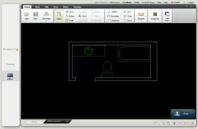
AutoCAD WS is a place to store drawings online, much the same way you can store Microsoft Office documents using Microsoft Office Web Apps or Google Docs. You can sign up for a free account and upload drawings. Once you are logged into your account, you can instantly open a drawing online–that is, you click a button and the drawing that you have open in AutoCAD appears in WS in your browser.
You can view uploaded drawings in your browser or on a mobile device at any time. You can share your drawings with others. You can even get a URL link so that you can share drawings with people who don’t have a WS account.
AutoCAD WS includes a number of basic drawing and editing tools. You can draw most basic shapes and perform most simple editing commands. When you click on an object, a sampling of tools appears next to the selected object.
Here you see a drawing displayed in AutoCAD WS.
Conclusion: Online sharing is the current wave and you can use WS to view drawings wherever you are–for example, on a building site. You should definitely try out WS to see if it will fit into your workflow.
Better snap mode
Have you ever thought that Snap Mode would be great for drawing but found it too annoying to keep on while selecting objects? Now, Snap Mode restricts your cursor only when you are specifying points. So, if you’re editing and want to select an object before choosing a command, or if you have a Select objects: prompt, your cursor will go wherever you want it to.
Conclusion: Why didn’t they do this earlier? This new behavior immediately feels right.
Nudge objects
Sometimes, you don’t need perfect accuracy; you just want to move an object a wee bit. Now you can nudge selected objects by holding down the Ctrl key and using any of the 4 arrow keys. Objects move 2 pixels each time you press the arrow key. If snap is on, they move the specified snap increment.
Conclusion: There’s a definite trend toward working with objects directly, without using a command. Nudging is familiar from many other programs, so it’s nice to have it in AutoCAD finally.
Delete duplicate objects
The OVERKILL command now has a button at Home tab>Modify panel (expanded). It deletes overlapping and duplicate objects. When you click the button, the Delete Duplicate Objects dialog box opens, where you can choose to ignore certain properties, decide if you want to combine partially overlapping colinear objects and more.
Conclusion: You should always clean up your drawings, so OVERKILL is nice to have.
New Pickauto setting
How many times have you tried to select objects with a window in a crowded drawing and picked on an object instead? Then you had to deselect the object and start over. The PICKAUTO system variable has a new setting, 2. PICKAUTO determines automatic windowing when you try to create a selection/crossing window before starting a command. The new setting causes object selection to occur only when you release the mouse button (rather than when you press it). So, if you click and drag (instead of clicking two opposing points), you can click on an object but not select it.
Note that the default setting is still 1, so you have to type pickauto on the command line and change the value to 2. Then you’ll need to get used to the fact that you can click and drag.
Watch the video, because you really have to see this to understand it.
Conclusion: I think you’ll like it! It will take a while to catch yourself before letting go of the mouse button so that you can drag, but once you get used to it, you’ll be able to avoid some frustration when selecting objects.
WBLOCK has its own button!
WBLOCK is the command that lets you save a block as a drawing. People have been asking AutoCAD to give this command respect for a long time and it finally happened. Go to Create Block drop-down list> Write Block. OK, it’s hard to find, but it’s there.
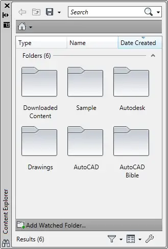
Content Explorer
The Content Explorer is supposed to be the next generation of the DesignCenter. You can do most of the things you can do with the DesignCenter, but not all. For example, you can’t insert images. The advantage is that it indexes folders that you specify for faster searching. There’s a complementary program, Autodesk Content Service, that you install on other, networked computers, to making searching faster on the network. You lose the “tree” format pane of the DesignCenter, which can be frustrating. In other words, you search for keywords, such as names of layers or text styles, instead of browsing.
Open the Content Explorer by going to the new Plug-Ins tab and choosing Explore. You start by clicking the Configure Settings button at the lower-left corner and then clicking Add Watched Folders in the dialog box that opens. Initial indexing takes a very long time, but when it’s completed, search is pretty quick.
Conclusion: I don’t do much searching over my 2-computer network, so it’s hard to me to judge. Right now, I still prefer the DesignCenter.
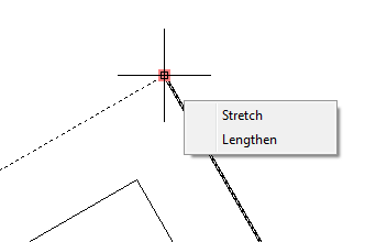
New multi-functional grips
AutoCAD 2011 introduced multi-functional grips for polylines. Grips are now multi-functional for lines, arcs, ellipctical arcs, dimensions, and mleaders in 2D and for 3D faces, edges, and vertices in 3D. The new arrays also have multi-functional grips. To use multi-functional grips, select an object and hover the cursor over a grip to see the options. To choose an option, choose it from the list of options. You’ll then see appropriate prompts. For example:
Line or arc endpoint: You can stretch or lengthen.
Arc midpoint: You can stretch or specify the radius.
Dimension endpoint: You can stretch, start a Continue or Baseline dimension, or flip the arrow.
Dimension midpoint: You have a number of choices for text placement.
Array upper-left arrow grip: You can change the row count, total row spacing, or axis angle. (Arrays have several types of multi-functional grips.)
Conclusion: I really like multi-functional grips. They are part of the trend toward direct manipulation of objects, without having to execute a command.
New interface for creating groups
I don’t know how many people use groups, but they’ve been around for a long time. They’re now much easier to create and the Home tab has a new Group panel. To create a group, just go to Home tab> Group panel> Group. At the prompt, select the objects for the group. If you want, use the Name and Description options to specify a name and description. A name is probably a good idea. That’s it.
Other buttons in the Group panel let you ungroup objects, turn object selection on and off (to temporarily let you select individual objects), and edit groups.
Conclusion: I don’t use groups much, but they’re definitely easier to work with now.
Quick Properties window
The Quick Properties window is now the default when you double-click most objects. Previously, the Properties palette opened.
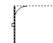
Fillet and chamfer preview
How many times have you created a fillet or chamfer and discovered that the radius was wrong? Then you had to redo it. Now, you get a preview before you commit. For example, start the FILLET command and set the radius. At the first prompt, select the first object to fillet. At the second prompt, hover over the second object, and you’ll see a preview, as you see here.
You can also now fillet splines.
Conclusion: Sweet!
Direct manipulation of the UCS icon
Continuing the trend to working without having to use a command, you can now change the UCS (User Coordinate System) by directly manipulating the UCS icon. You can move it, rotate it, and more, using its grips. Use its right-click menu for more options.
Conclusion: SO much nicer than the UCS command!
Preview for lofts and more
We’re now moving into 3D features. Just as you can see a preview for fillets and chamfers, you can see one for the following 3D objects: loft, surfblent, surfpatch, surfillet, filletedge, chamferedge.
Conclusion: Previews really save you time because you have to undo your mistakes less often.
New 2D view object to view 3D models in 2D
Over the years, there have been many techniques for viewing 3D models in 2D. Among them are the following:
Now comes a new method. The 2D view object is a new object type. A 2D snapshot of your model at the moment you create the view object. It isn’t dynamically linked to the model, but if you change the source model, you can update your views. You can use 2D view objects to import 3D models from other applications, including Inventor. Here, I’ll just cover them for use within AutoCAD.
You display view objects on a layout, but not in a viewport. The VIEWBASE command creates the view objects and there are several related commands as well. The command creates two related orthogonal views, such as a top and a front view. You can also create isometric views. Watch the video.
Conclusion: They are a little clunky, but I’m hoping they’ll become more flexible. It’s a start to what may become a useful feature.
New BLEND command
The BLEND command creates splines between lines, arcs, polylines, splines, helixes and elliptical arcs. It’s like a fillet, but it’s a spline, not an arc. You can control the bulge of the curve using the Continuity option. In this video, I just use the default setting.
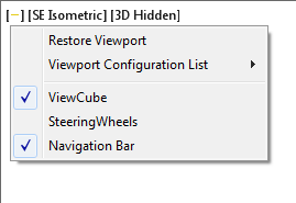
Viewport settings for controls, viewpoint and visual style
At the upper-left corner of the viewport/drawing area, are easily accessible settings for viewport controls, viewpoint, and visual style. Here you see the viewport control drop-down list. Just click the drop-down list you want and choose one of the options.
Conclusion: I like having the settings right in the viewport and not having to search for them on the ribbon.
What do you think?
Let me know what you think! Please add a comment! Which feature seems most useful to you?
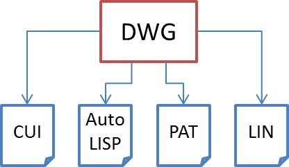
All AutoCAD drawings are connected to related files. At the very least, all drawings need access to a customization user interface (CUI) file. Some drawings also need to access fonts, plug-ins (such as AutoLISP and VBA files), linetypes, and hatch patterns. Drawings may have externally referenced drawings (xrefs).
You can make your AutoCAD life easier by understanding the support file search path and the project files search path. If you sometimes get a message that AutoCAD can’t find a necessary file, you may be able to solve this problem by working with the support file search path. AutoCAD looks for outside files first in the same folder as the current drawing, then in the support file search path. If the file is not in either place, you’ll get a message that AutoCAD can’t find the file.
Work with the support file search path
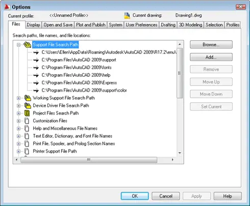
The support file search path is one or more locations where AutoCAD looks for menus, fonts, linetypes, and hatch patterns. It also looks there for drawings to insert (using the INSERT command) and plug-ins. AutoCAD comes with a default support file search path, which varies based on your version of Windows. To find it, choose Tools> Options. This opens the Options dialog box.
Quick Tip: A shortcut to open the Options dialog box is to right-click in the drawing or command-line area with no objects selected, and choose Options.
Click the Files tab. Then click the plus sign next to the first item, Support File Search Path, to expand the list.
The top item is your default location. Your menu, font, linetype, and hatch pattern files are there by default.
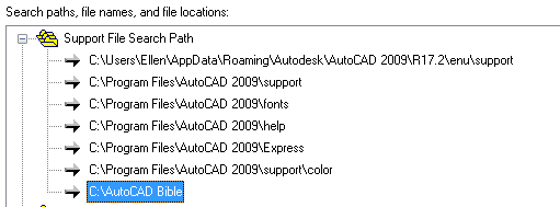
If you want to create your own menu, font, linetype, and hatch pattern files, I recommend creating a folder for them and adding that folder to the support file search path. In this way, you don’t interfere with the default installation of AutoCAD. Also, if you need to uninstall and reinstall or upgrade AutoCAD, your files are safer (although AutoCAD usually saves these files during an upgrade).
To add your own folder, select the Support File Search Path item, and click the Add button. A new text box opens at the end of the list where you can type in the path, but it’s usually easier to click Browse. Then navigate to the folder in the Browse for Folder dialog box, select it, and click OK. The new path appears in your list.
You can create several folders for files and add them to your support file search parth. For example, many people put their AutoLISP and VBA files in a separate folder and add it to the support file search path.
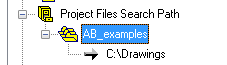
Specify the search path for xrefs
The Project Files Search Path item is for xrefs. You can specify a project name for a drawing, using the PROJECTNAME system variable. Then, that drawing will look for xrefs in the project files search path related to that project name. You use this to ensure that the drawing can find the xref even if it’s moved and therefore isn’t in its original location. Project names are also used for images and DWF underlays.
To add a project name in the Options dialog box, click the Project Files Search Path item to expand it. If you haven’t used this item before, a new line appears, called Empty. Click Add. Then a new project appears, called Project1. It’s highlighted, so you can rename it. Choose a name that’s easy to type, as you’ll have to type it on the command line.
To add a location, follow these steps:
Click Add.
Either type in a path, or click Browse to navigate to it, as previously described.
Click OK, and your new path appears in the listing.W
When you’re done, click OK to close the Options dialog box. The project name you specified is now stored in the Windows Registry.
To use a project files search path, enter projectname on the command line. At the Enter new value for PROJECTNAME, or . for none <“”>: prompt, enter the projectname that you specified in the Options dialog box. If you enter a name that you haven’t listed in the Options dialog box, you get the following message:
“hello” not found in the registry. Use the Options dialog Files tab to create the project name and set the project search paths.
The next time you open the drawing, AutoCAD will know where to search for the xrefs for that drawing, even if they’ve been moved.
Important: While we don't collect cookies, some of our 3rd-party services (such as PayPal and WordPress) do, to give you a safer and better browsing experience. Read about how we use cookies and keep your personal information secure by reading our Privacy Policy here.