You should have at least 1 text style for your dimensions and perhaps a text style for each dimension style.
When you create a dimension style, you can create a text style from within the New Dimension Style dialog box. On the Text tab, click the Ellipsis button as shown here.
The Text Style dialog box opens.
The secret here is to set the height of the text style to zero. This allows you to set the height as part of the dimension style. If you instead specify a height in the text style, that height overrides the dimension style’s setting.
If you want the default settings, just click Cancel. Otherwise, make the desired changes and click Apply, then click Close.
Now, you can set the text height in the New Dimension Style dialog box, as you see here.
Now, go do some dimensioning!
What techniques do you use to make sure that your text looks the way you want it to in your dimensions? Leave a comment!
Xrefs (external references) let you view another drawing within your current drawing without actually inserting that other drawing.
Why use xrefs?
Xrefs keep your drawing smaller.
Each time you open a drawing, AutoCAD loads a current copy of the xref, so that you always have the most updated version. The drawing contains a link to the xref, so you don’t have to worry if what you’re seeing is outdated.
You can attach and detach xrefs easily. You can also load and unloaded them to display or hide them, without losing the connection.
Xrefs are ideal for times when you need to reference another drawing but don’t want the relationship to be permanent. They are also ideal for situations in which multiple people work on a drawing. For example, both an electrician and a plumber might add an architect’s plans to their drawing as an xref.
Attach an xref
Follow these steps to attach an xref:
Choose Insert tab> Reference panel> Attach (the ATTACH command) to open the Select Reference File dialog box. (In earlier releases, this was the XATTACH command.)
Make sure Drawing (*.dwg) is visible in the Files of Type drop-down list in the dialog box. If not, click the list and choose it.
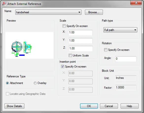
Navigate to the drawing you want to attach, choose it and click Open. The Attach External Reference dialog box appears.
Set the Reference Type to Attachment (the default). If you want, you can specify the scale, insertion point, and rotation in the dialog box. Click OK.
If you used the settings you see in the dialog box here, you’ll be prompted for an insertion point. You’ll see an image of the xref, so you can place it by eye if you want. Click to place the xref.
Notes:
An overlay is useful when you’re sharing drawings over a network. If someone else attaches your current drawing, that person doesn’t see the overlay, only the main drawing.
In the Scale section, you can check the Uniform Scale checkbox to ensure that the Y and Z values are always the same as the X value. This ensures that the xref isn’t distorted from its original ratios.
Do you use xrefs a lot? What tips do you have to make using xrefs easier and more efficient? Please leave a comment and let everyone know!
Draw and edit faster and easier with these top 25 productivity tips every AutoCAD user should know. Check out “Top Productivity Tips Every AutoCAD User Should Know” at http://www.ellenhelps.me/25-Productivity-Tips
You can auto-fill data in an AutoCAD table like you can in an Excel spreadsheet. This makes it easy to copy data along a row or column and to automatically create incremental data, such as consecutive numbers.
To auto-fill cell data, click in a cell that you’ve already filled with a value. Click and drag the cyan (turquoise) diamond to the desired cell and click.
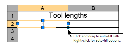
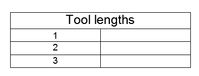
To auto-fill incremental data, such as consecutive numbers, drag across two cells that already have incremental data. For example, if you typed 1 and 2, drag across those cells. Then click and drag the cyan diamond to the desired cell and click. Before the final click, a tooltip shows you what results to expect. Click to place the data.
I’ve written posts about how to create specific types of dynamic blocks and about some of their features, but I’ve never explained when and why you would use a dynamic block.
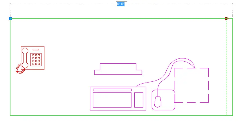
If you have a block library that contains variations on an object or component and you insert them at various scales and rotations angles, you can probably save a lot of time with dynamic blocks. For example, you may have a desk that comes in various lengths. You can create one dynamic block to replace all the individual variations. Moreover, your dynamic block will give you even more flexibility to add additional lengths.
It takes some time to define a dynamic block — of course, simple ones take less time but complex ones can take a long time. For this reason, the most common use for dynamic blocks is to create a block library. That means you don’t usually define dynamic blocks for your current drawing. Instead, you create them and save them to use in future drawings.
But if you’ll need to draw several components in variations in your current drawing, you can create a quick dynamic block to save yourself some time.
The first part of the process of creating dynamic blocks is to define the block. Here’s an overview of the workflow:
In your block library drawing or a new drawing, create the block.
Choose Home tab> Block panel> Block Editor (BEDIT command) or just double-click the block. In the Edit Block Definition dialog box, choose the block, and click OK to open the Block Editor. (You can also start the BEDIT command, name the block, and create the objects in the Block Editor.)
Add parameters and associated actions, or geometric parametric constraints.
Save the block definition in the Block Editor.
Close the Block Editor.
If the drawing will contain just this block, use the BASE command to set the drawing origin where you want the insertion point to be, usually somewhere on the block. You do this when creating a block library that has one block per drawing.
Save the drawing.
You may want to follow this process for any number of blocks. When your blocks are defined, do the following to insert your dynamic blocks:
In your current drawing, either use the INSERT command to insert the drawing containing the block, or use the DesignCenter to choose the block from within the drawing.
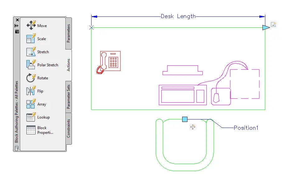
Select the block to see its special grips. These grips show you where you can modify the block.
Usually, you click and drag a grip to modify the block. Some dynamic block parameters involve choosing a visibility or option from a drop-down list or table.
Here you see the process of stretching the desk length.
When and why do you use dynamic blocks? What is your process for creating and storing them?
This is a guest post by Sanjay Kulkarni, an AutoCAD programmer.
This post describes the method to load an AutoLISP program in an open drawing.
Some basic & fundamental information before we move to the procedure
An AutoLISP program runs inside (in the same workspace of) an open drawing. Therefore it is necessary to load the program in each individual drawing you want to use the program in. You can load a program into a drawing at any time.
Once you load the program in a drawing, it remains loaded into that specific drawing until the drawing is closed. This means that you can use the functions in the program multiple times once you load the program.
The flip side is that you can’t unload an AutoLISP program once you load it except by closing the drawing.
If you want to use the same program in multiple drawings, you will need to load the program in each individual drawing even if there exists a drawing in which the program has been already loaded.
Loading an AutoLISP program
Now to the action:
Type appload at the command prompt (In AutoCAD 2012, you can go to Manage tab>Applications panel>Load Application.). This will display the Load/Unload Applications dialog box.
Click the History List tab at the bottom of the dialog box. In case the program was previously loaded in any drawing with Add to History checked, it will be listed there. Select the desired file in the list and go to step 7. Otherwise, go to step 3.
Make sure that Files of type displays the .lsp extension.
Using the LookIn drop-down, you browse to the desired location (folder).
If you want to be able to use step 2 above in future, select the Add to History checkbox.
Select the .lsp file to load in the window.
Click Load. If the file is successfully loaded, a message to that effect is displayed at the bottom of the dialog box. Also if you have checked Add to History, the names of loaded programs are added to in the History List tab of the window.Click the Close button to close the dialog box.
You are now ready to use the functions in the loaded files.
Notes:
You can select multiple files in the History List or the browser using Shift & Control keys and then click the Load button to load all the selected files simultaneously.
You can double-click on an individual file to both select and load it. Then you don’t need to click the Load button.
When you double-click on a file in History List with Add to History checked, the file name is added again to the History List. You can remove filenames in the History List by selecting the file and clicking the Remove button.
If you load a file multiple times in a drawing, AutoCAD does not generate any error and overwrites the previous version of the loaded file.
For a quicker method of loading a program, see the tip, “Loading AutoLISP programs quickly.” This will also obviate the need to load the program in each drawing.
Sanjay Kulkarni is an experienced CAD (AutoCAD, Inventor, SolidEdge, CATIA, NX) programmer and a member of the Autodesk Developer Network. He is fluent in AutoLISP, VBA, and VB.NET. He has written for AugiWORLD and Inside AutoCAD (a monthly magazine that has since gone out of publication). You can contact him at sanganakskha@gmail.com
When you trim objects, the first prompt asks you for a cutting edge. Gerardo Martinez e-mailed me a reminder that you can press Enter (or right-click, depending on your right-click settings) to specify all objects as potential cutting edges.
Then you just select the part of the object that you want to trim and AutoCAD automatically trims it at the closest possible cutting edge.
So remember:
Start the TRIM command
At the Select cutting edges … Select objects or <select all>: prompt, press Enter.
Select the object(s) to trim.
There’s another shortcut for trimming objects—the EXTRIM command. EXTRIM lets you choose an object and then one side of the object. Here are the steps:
Type extrim on the command line.
At the Pick a POLYLINE, LINE, CIRCLE, ARC, ELLIPSE, IMAGE or TEXT for cutting edge: prompt, select one of the listed objects.
At the Specify the side to trim on: prompt, pick on one side of the selected object.
What tips do you have for trimming objects? Leave a comment!
Start the APPLOAD command. In AutoCAD 2012, you can go to Manage tab>Applications panel>Load Application.
In the Load/Unload Application dialog box, make sure that the Files of Type drop-down list displays the .lsp extension. In the Look In box, navigate to the AutoLISP file and select it.
Click the Load button. You should see a message at the bottom of the dialog box saying that the file was successfully loaded.
Follow the prompts. At the Select the line to align rectangle with: prompt, select the line to align the rectangle with. The program repeats the prompt until you select a line or press the Escape key to abort the program.
At the Specify first corner point or [Chamfer/Elevation/Fillet/Thickness/Width]: prompt, specify the first corner of the rectangle. You can now see that the rectangle is aligned with the line.
At the Specify other corner point or [Area/Dimensions/Rotation]: prompt, specify the other corner of the rectangle to finish the routine and create a rectangle aligned with the selected line.
Tip: You can repeat the command in the drawing as long as the drawing is open. But if you open another drawing you will need to reload the program. To avoid having to do this, you can add it to your Startup Suite. In the Load/Unload Application dialog box, drag the AutoLISP file from the list of files at the top to the Startup Suite in the lower-right section of the dialog box.
I won’t show you the actual code in all my posts, but this one is simple enough that it will be useful to look at its structure. As I said, you can use this same structure for many situations. It’s similar to a script file; you are using the COMMAND function to execute an AutoCAD command. The code also defines an alias, RA. The PAUSE function waits for your input. Of course, the code also defines some variables, does some error checking, sets up the prompts, and a little more.
Do you use AutoLISP in this way? Let us know how you use simple routines like this in your work–leave a comment!
Sanjay Kulkarni is an experienced CAD (AutoCAD, Inventor, SolidEdge, CATIA, NX) programmer and a member of the Autodesk Developer Network. He is fluent in AutoLISP, VBA, and VB.NET. He has written for AugiWORLD and Inside AutoCAD (a monthly magazine that has since gone out of publication). He can be contacted at sanganakskha@gmail.com
You may have objects on the wrong layer–in fact, you may not want to even keep the layer those objects are on. The solution is the LAYMRG command. This is a guest post by Will Forty, who has a great blog called HowToAutoCAD.com.
He writes:
“I was recently asked if there was a quick way to put all the objects on a certain layer onto another layer, which reminded me of this little beauty that you need to know about.
LAYMRG is a command for manipulating layers in AutoCAD, and gives you the facility to merge two or more layers together so that the objects end up on the final target layer that you choose. The old layers that now contain no objects are removed, effectively merging the layers. Precisely what you’d expect from a command named LAYMRG.
Whilst this feature alone is very useful, this command can also be really helpful for getting rid of unwanted layers in your drawing. This has happened to all of us – you’re working away and there’s a layer in the drawing that refuses to allow you to delete it! Probably this is because it’s used within a block, or perhaps a block within a block, and it can be a real nightmare trying to identify where the offending object is that is using it.
A workaround to the problem is to just merge it with, say, layer 0, so that you get rid of the offending layer, and whatever was using it now is on Layer 0.
So that’s my piece for today – LAYMRG, a really useful tool you should remember!”
I just wanted to add the prompts:
At the Select object on layer to merge or [Name/Undo]: prompt, select an object on the layer that you want to delete. All objects on that layer will move to the layer you’ll specify next. The prompt repeats, so press Enter to continue.
At the Select object on target layer or [Name]: prompt, select an object on the layer that you want to merge to. All objects on the first layer will now be on this target layer.
You’ll need to confirm the change.
Will Forty’s HowToAutoCAD blog aims to show you “How to use, customise and ultimately master AutoCAD.” I suggest that you browse through the posts. If you find it valuable, you can subscribe to get e-mail updates when he publishes a new post.
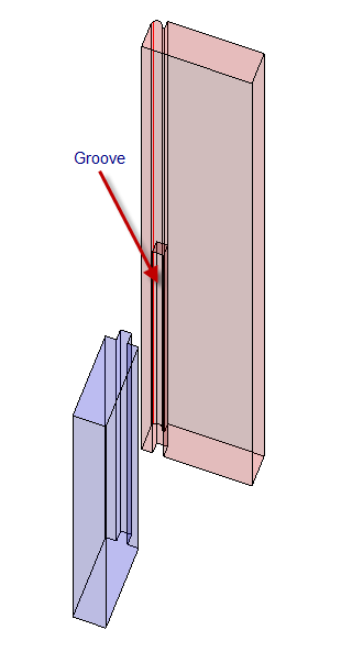
Sometimes you need to cut out part of one 3D object to fit another object. For example, in tongue & grove construction, you need to cut out the groove to fit the tongue. You can make this process easy with an option of the INTERFERE command.
Follow these steps:
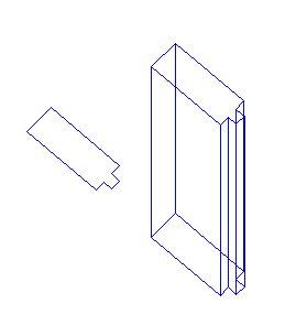
1. Create an object with a tongue. For example, I drew a closed polyline and extruded it with the EXTRUDE command. (You could also create two boxes and use the UNION command to join them.)
2. Create an object that will receive the tongue. For this example, I’ve made a length of beaded face frame stock. It’s taller than the piece with the tongue, so the associated groove needs to stop at the end of the tongue. Again, you can draw a closed polyline and extrude it.
3. Position the two parts in the orientation that they will take when your model is complete. This is important, because we will be using the actual geometry of the two parts to create their final relationship. You can see that the tongue model interferes with the taller model that will have a groove (to accommodate the tongue).
4. Switch to a layer whose color contrasts with the colors of the existing objects’ layers.
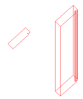
5. Start the INTERFERE command. At the Select first set of objects or [Nested selection/Settings]: prompt, select both object and press Enter when the prompt repeats.
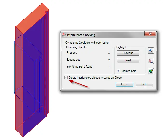
6. At the Select second set of objects or [Nested selection/checK first set] <checK>: prompt, press Enter to check for interference and open the Interference Checking dialog box.
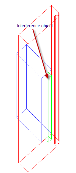
7. In the dialog box, make sure to uncheck the Delete Interference Objects Created on Close check box. The result is that you create an interference object. You see it here in green.
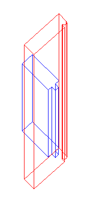
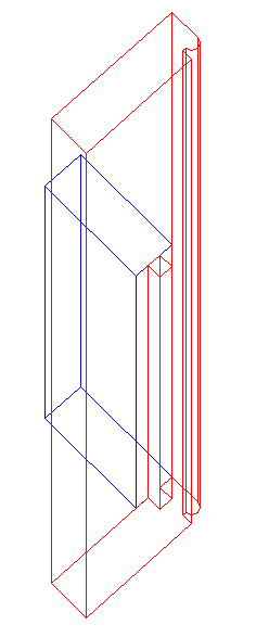
8. Start the SUBTRACT command. At the Select solids, surfaces, and regions to subtract from .. Select objects: prompt, select the solid that will have the groove and press Enter to end selection. At the Select solids, surfaces, and regions to subtract ..Select objects: prompt, select the interference object you created and press Enter to end selection. You have just created the perfect groove for the tongue.
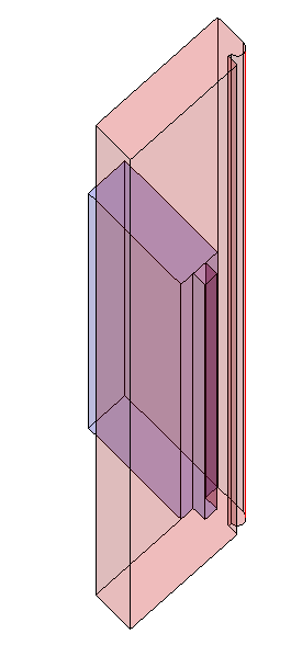
Here’s the same model and view with the Xray visual style.
Finally, I separated the objects and changed the viewpoint so you can see the groove more clearly.
Thanks to Bill Walker for submitting this tip! He is a 30+ yr. veteran of the Cabinet-Making Business who has focused on 3D modeling in AutoCAD for the last 10 years, ever since he realized that modeling in 3D let him solve problems the same way he would in the shop, but with less mess and noise. He’s a freelance AutoCAD modeler.
A reader of my book, AutoCAD & AutoCAD LT Bible (the 2010 version) wrote me the following:
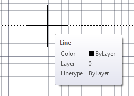
“Whenever the mouse crosshairs land on a line in a drawing, a small ‘window’ appears, listing
Line.
Color. By layer
Layer. Plan
Linetype. Continuous
This is extremely annoying and I can’t see how I can prevent this entirely superfluous ‘window’ from appearing whenever the mouse lands on a line, or is left parked on a line. You can imagine my frustration when working on a graph, with a grid as a background. This was never the case with previous versions of AutoCAD, and in my opinion, is not an ‘upgrade’ but a retrograde move.”
As you can see, he is quite annoyed. Frankly, I hardly even notice this and at first I thought he was talking about the Quick Properties window that opens when you select an object. But he was talking about hovering over an object.
The solution is to change the value of the ROLLOVERTIPS system variable. The default, 1, shows information about an object when you roll the mouse over it. Change the default to 0 to make it go away. This system variable is saved in the Registry, so once you change it, you won’t see that tooltip in any of your drawings.
It’s just 2 steps:
Type rollovertips on the command line and press Enter.
Type 0 and press Enter again.
By the way, to make the Quick Properties box go away, just click the Quick Properties button on the status bar to deselect it.
Important: While we don't collect cookies, some of our 3rd-party services (such as PayPal and WordPress) do, to give you a safer and better browsing experience. Read about how we use cookies and keep your personal information secure by reading our Privacy Policy here.