Xref in AutoCAD means ‘external reference’ to other drawing files. One file can reference many other files and display them as an overlay (or background) on the main file.
Xrefs are usually used in larger projects to manage complexity of the main files, however, it is also beneficial in smaller and less complex projects where greater control of information layering is required.
In this example, we will look into creating a simple Xref of grid system for a floor plan:
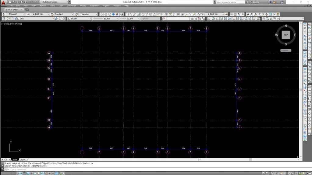
Create a drawing file containing grid lines, grid tags and general dimensioning
Save file with an identifier name (i.e. 0-FP-A-GRID.dwg) and preferably under the same folder as the project file
In the project folder, create and open a new drawing file where the floor plan will be drawn In this case, we will name the floor plan file as 0-FP-A-UL.dwg
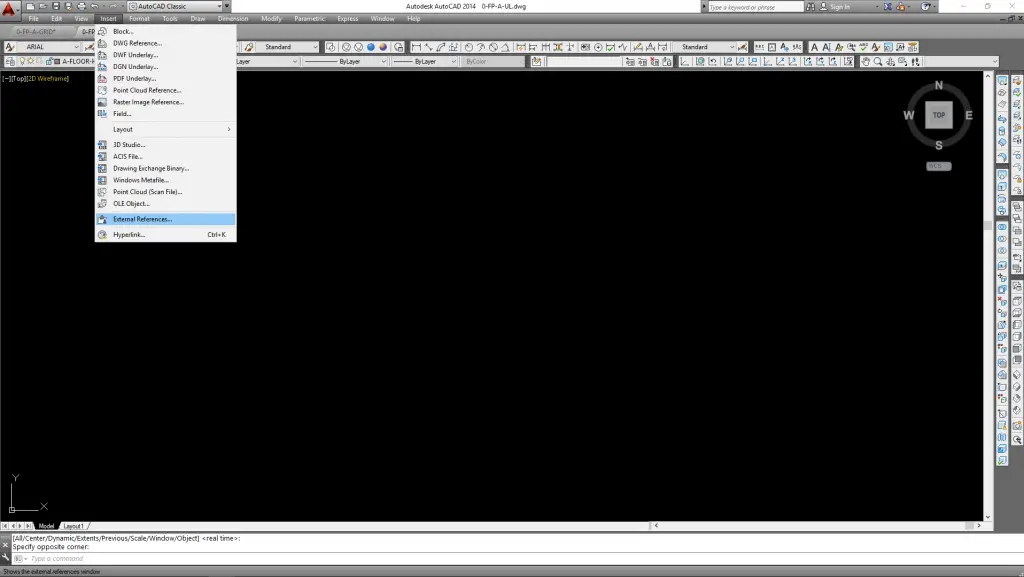
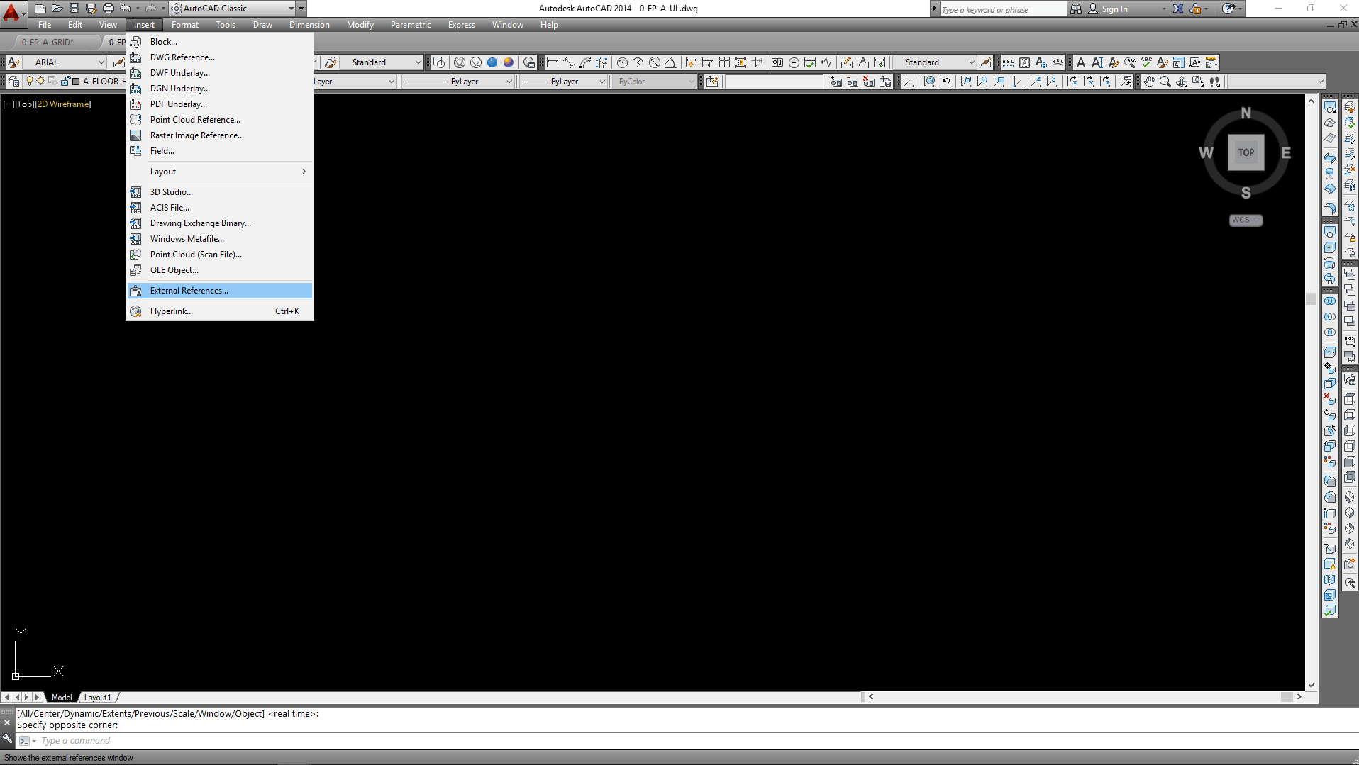
In 0-FP-A-UL.dwg, click Insert/External References
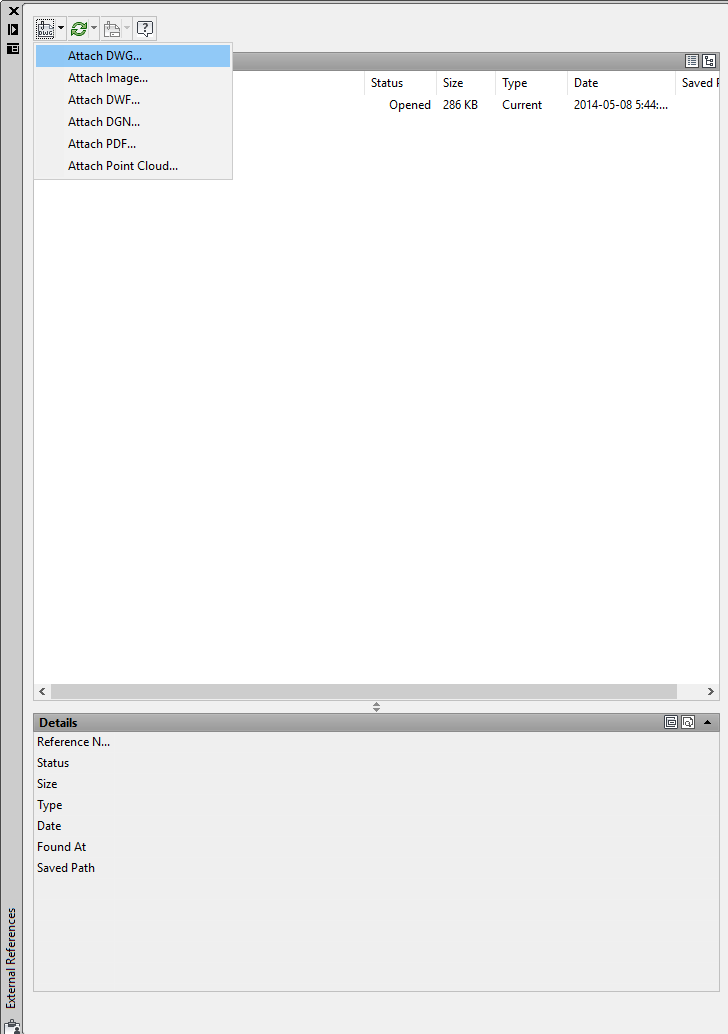
This will bring up the ‘External References’ window as follow. Pull down the ‘DWG icon’ on top right corner, select ‘Attach DWG’
In the ‘Select Reference File’ window, select the grid file 0-FP-A-GRID.dwg and click ‘Open’
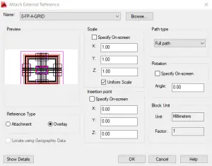
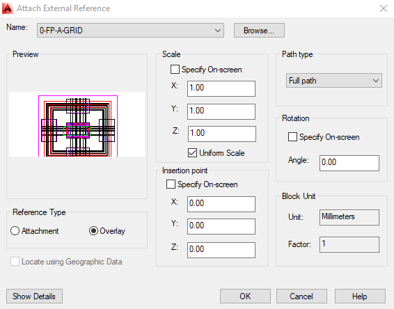
This will bring up ‘Attached External Reference’ window. Check ‘Overlay’ under Reference Type and click ‘OK’
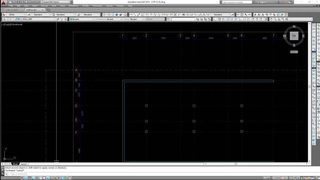
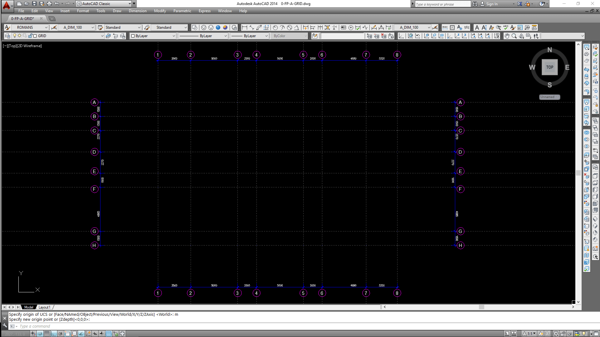
The grid file is now loaded into the floor plan file. It is recommended to assign a unique layer for the Xref file and have this layer locked to prevent accidental shift/moved from its origin
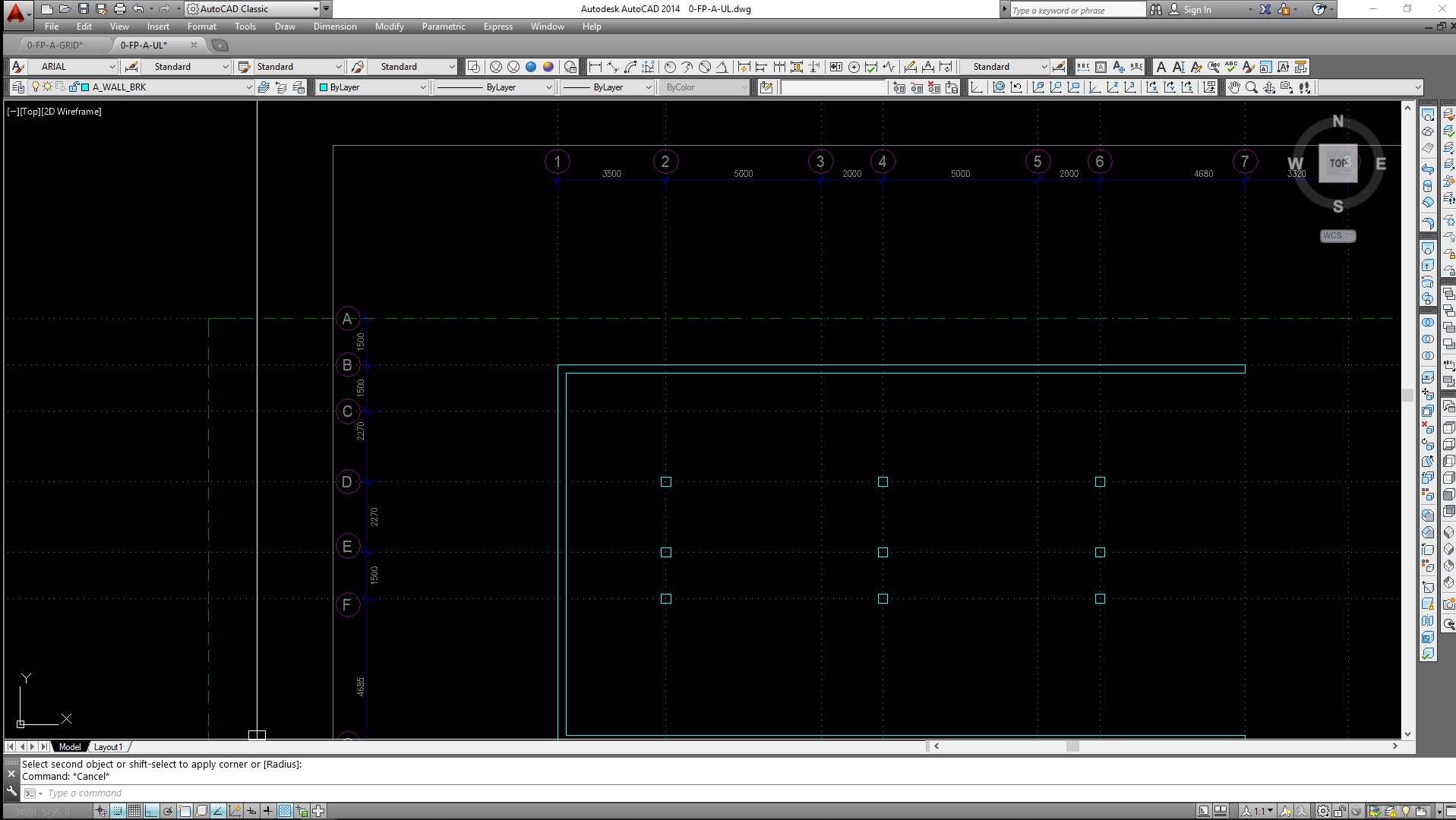
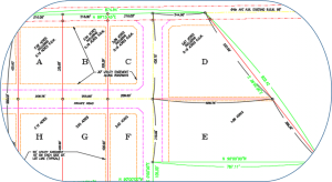
Building elements such as walls and columns can be drawn over the Xref file as follow with the grid lines as references
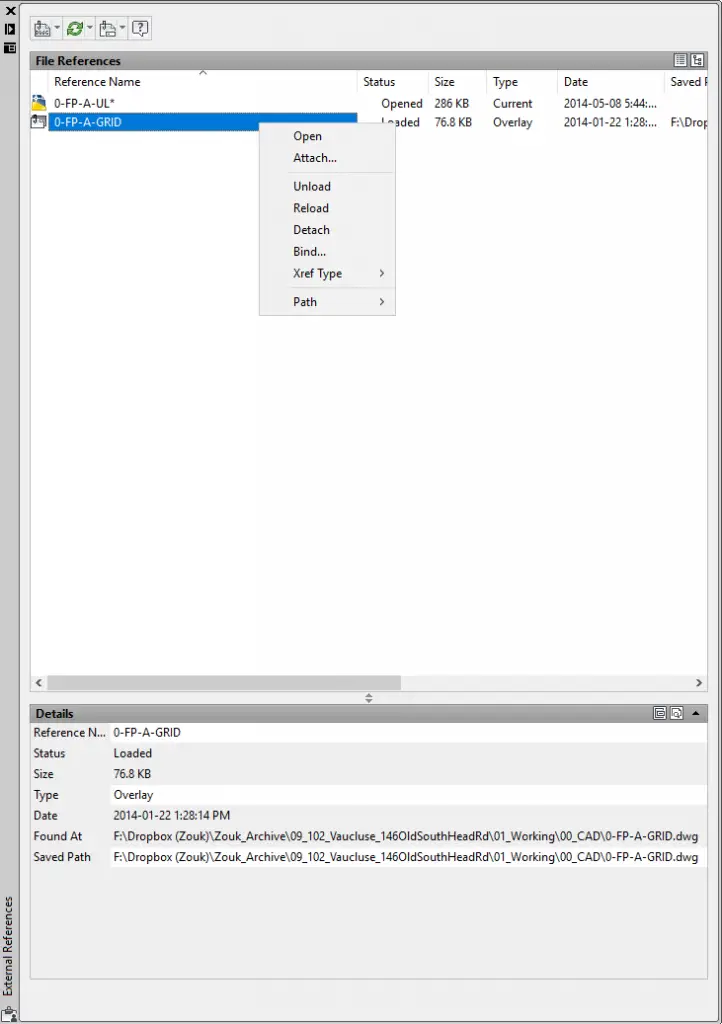
To manage Xref file, type “Xref” in the command prompt to bring up the ‘External References’ window again. Right click the Xref file for editing options (such as Unload) to temporary turning off the file or Detach to delete the file.
Have you noticed how grip-editing a viewport is different from grip-editing a rectangle?
When you grip-edit the upper-right corner of a viewport to stretch it, the viewport keeps its rectangular shape. You can freely choose your new corner location, so you’re not just scaling. You can change the proportion between the width and height, all without losing its rectangle-ness.
Stretching a viewport
But when you grip-edit the upper-right corner of a rectangle, the rectangle is distorted. The rectangle doesn’t know that it’s supposed to remain a rectangle. AutoCAD just thinks of it as a 4-sided, closed polyline. Indeed, select it and check in the Properties palette (Ctrl+1) and you’ll discover that it is indeed just a polyline.
Stretching a rectangle in AutoCAD
AutoCAD 2010’s geometric parameters can help you easily create a rectangle that knows it’s a rectangle. And, what is a rectangle? Well, “rect” means right, as in 90°. “Angle” is self-explanatory. So, we need to ensure that the angles will stay 90°.
Here’s how:
Draw a rectangle.
Go to Parametric tab> Geometric panel, and click the Perpendicular button.
At the Select first object: prompt, click the top horizontal line of the rectangle.
At the Select second object: prompt, click the left vertical line. You’ll see the Perpendicular icon near the upper-left corner of the rectangle.
Repeat the process for the two lines that meet at the lower-left corner and the lower-right corner.
A rectangle with 3 perpendicular geometric constraints
Note: If you try to do all 4 corners, you’ll get a message telling you that AutoCAD can’t apply the constraint. That’s because when you have 3 corners constrained to perpendicular, the last corner is superfluous, and is therefore an overconstraint.
You can’t overconstrain an object in AutoCAD
Now, you can grip-edit that upper-right corner and it will behave just like a viewport!
This is a guest post by Ben Richardson. Ben is director of Acuity Training, a UK based IT training business. Acuity Training focuses on high quality classroom-based IT applications training including AutoCAD (of course!), Adobe and Microsoft.
You can’t succeed in 3D drawing without learning how to view your model from various angles. In this tutorial, you will become familiar with AutoCAD’s Isometric views, learning to move and alter AutoCAD objects in 3D. You will do this by creating a simple 3D representation of a door and manipulating it to suit your needs. It isn’t an exact model but will give you the experience you need to create more precise 3D models.unit
1) Specify settings
Before we start, you need to make sure your settings are identical to mine for the tutorial to work.
We’ll be working in inches. If you customarily work in the metric system, type DWGUNITS on the command line and type 1, for inches.
Type UNITS and in the Units dialog box, under Length, Type, choose Architectural and click OK.
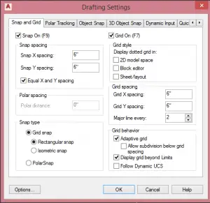
To specify the Snap and Grid settings, right-click the Gridmode button on the Status bar and choose Grid Settings.
This is a guest post by Andreea Georgiana. She is a CAD enthusiast who likes using the power of Computer Aided Design to create cool useful designs, from conception to 3D printing. She has a 21-day AutoCAD course at tutorial45.com.
She says, “Being able to use Computer Aided Design software to bring your ideas to life is one of the things I totally disagree only engineers should be able to do. With the numerous advantages of being able to move past the level of a 3D model to actually having the model 3D printed, anyone should consider learning at least the basics of modifying a CAD model.
“As a CAD hobbyist, wife and mother, I have found many cases where a customized solution designed myself has solved a problem in the exact manner I wanted, thanks to the power of CAD and 3D printing. You can find some free tutorials here.”
* * * * *
Before I start, here are 2D and 3D images of the model you’ll draw in this tutorial,
This is a guest post by Viktor Rask, founder of CAD Modeand author of the e-book 101 CAD Exercises – Learn & Improve Your Skills. He is a mechanical engineer (BSc.) with a passion for CAD and 3D! He also loves to help others grow.
* * * * *
When I first started to learn CAD a few years back, I had a major problem with my learning process. I couldn’t find any exercise material. I searched and searched but couldn’t find anything useful. I decided to create the 101 CAD Exercises book to help others speed up their learning process and make it more hands-on and fun. If you want more exercises like this, you can get them here. (The exercises are 2D and 3D drawings without instructions so that they are not specific to AutoCAD.)
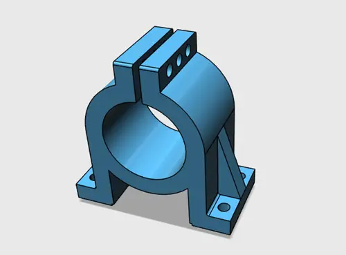
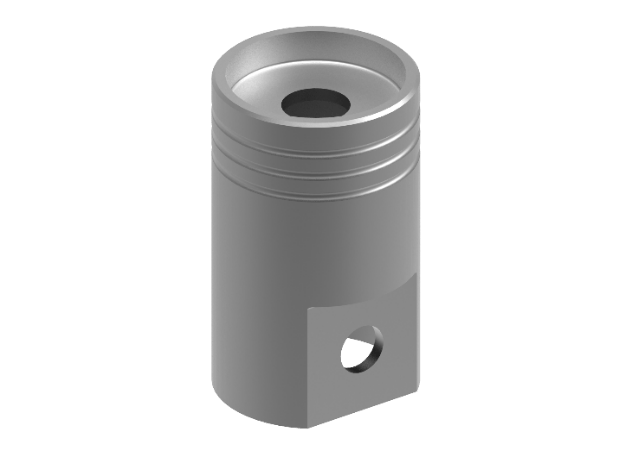
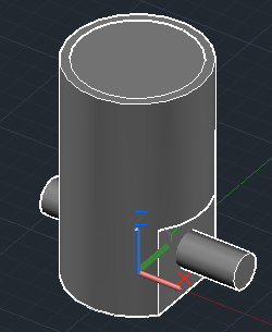
In this tutorial, you will learn how to create a piston using 3D geometry in AutoCAD. To do this you will use the 2D drafting and annotations and the 3D features. I assume that you are already a bit familiar with the basic 2D drawing commands such as LINE, CIRCLE, TRIM, etc. The final model should look something like this in 3D.
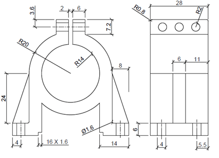
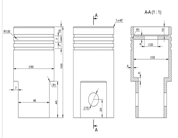
Here are the 2D drawings:
Remember that using gridmode (F9) and snapmode (F7) can be helpful between drawing tasks. For this exercise, I’ve been using AutoCAD 2017 but it will work with previous versions as well as other CAD software. Your commands and shortcuts might differ with other versions, though. The dimensions that are used in this exercise are originally metric but since it’s all proportional you can use the same values but with imperial units instead. I’ve decided to keep the measurements unitless for this exact reason.
Start a new drawing in AutoCAD.
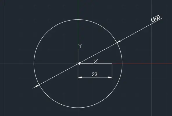
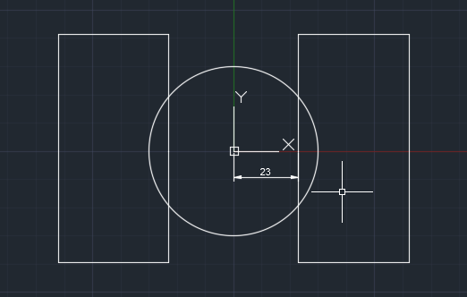
Draw a circle with a diameter of 60 and place its center on the origin (0,0).
Draw a horizontal line that starts at the origin and a length of 23. This line will be used as a reference length for the next step.
Draw a rectangle using the RECTANG command as shown on the right side of the image below, using the endpoint of the line as a guide to place the rectangle. The dimensions of the rectangle don’t need to be exact but they must exceed the circle perimeter as we use it as a cutter. Then mirror the rectangle using the start point of the line (or the center of the circle) for the mirror line. Remember to erase the reference line that you used to create the rectangle.
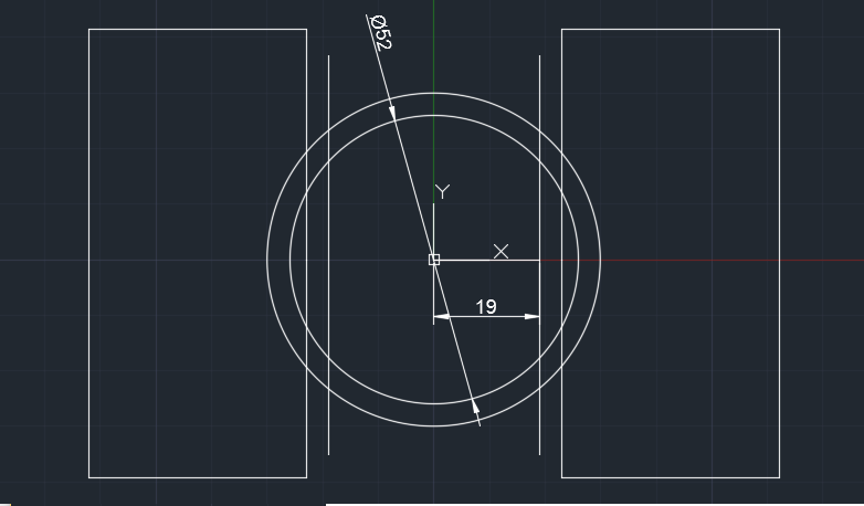
Now draw a concentric smaller circle with a diameter of 52. Also, draw a vertical line 19 units to the right of the center of the circles as shown below and mirror it. As with the rectangles, the lines need to exceed the circle perimeter.
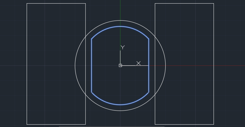
Now use the TRIM command and use the vertical lines as edges to trim the inner circle. Resize the 2 vertical lines so that they end at the top and bottom arcs. Then use the JOIN command to make the following shape in the center.
Click the gear (Workspace Switching) icon on the bottom right of the screen and choose 3D Basics instead of Drafting and Annotation. Also choose a 3D viewpoint so you aren’t looking at plan view.
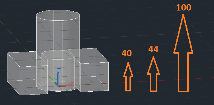
Now use the EXTRUDE command to extrude the shapes to make a 3D model. The Z dimensions (shown below) are 40 units for the rectangles, 44 units for the central shape, and100 units for the circle. This image is using the X-ray visual style.
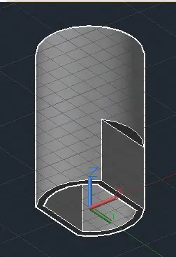
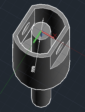
Now start the SUBTRACT command and subtract every shape from the main cylinder. Remember that first you must select the main cylinder, press Enter and then select the objects you want to subtract from it. You might need to change your viewpoint or visual style, especially to subtract the central shape. Now you should have a model looking like this:
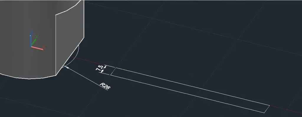
Now you should go back to the 2D Drawing and Annotation and return to a top 3D view such as SE Isometric if necessary. Drawa concentric circle with a diameter of 52 and a rectangle (using the RECTANG command) with a height of 7.5 and one of its sides on the x-axis as shown in the image. The length of the rectangle should exceed the cylinder diameter, which is 60.
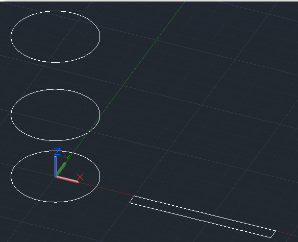
You can isolate (hide) the main body by right-clicking on it and choosing Hide or Isolate>Hide. Then use the COPY command to create two more circles, 44 units and 100 units in the z-direction. After this, delete the base circle. Go back to the 3D Basics workspace.
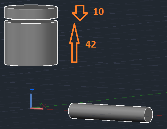
Use the EXTRUDE command on the 2 circles; the lower circle should be 42 units upwards and the circle on top should be 10 units downwards. Then use the REVOLVE command on the rectangle to make another cylinder. Specify the X axis as the axis of revolution and use the default 360° revolution.
Now right-click and end object isolation (Unhide). Using the MOVE command, bring the thin cylinder 20 units upwards in the Z-direction and move it towards the main body of the piston so that it extends on both sides.
Now subtract the 3 cyllinders from the main body. You can use the Bottom view for easier access.
In the 2D Drawing & Annotations workspace, draw a concentric circle with a diameter of 20 units. Use the EXTRUDE command to create a cylinder that is higher than the main body. Then subtract it from the main body.
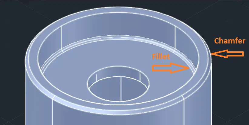
Now use the CHAMFEREDGEcommand pick the outer edge of the top face of the cylinder, press Enter and type d to give it a distance from the edge. Choose 1 unit as the distance and then press Enter. You must enter the distance twice to give it the same distance from both edges.
Start the FILLETEDGE command and then pick the inner edge of the top face of the cylinder, press Enter, and type r to give the fillet a radius. Choose 1 unit as the radius and press Enter.
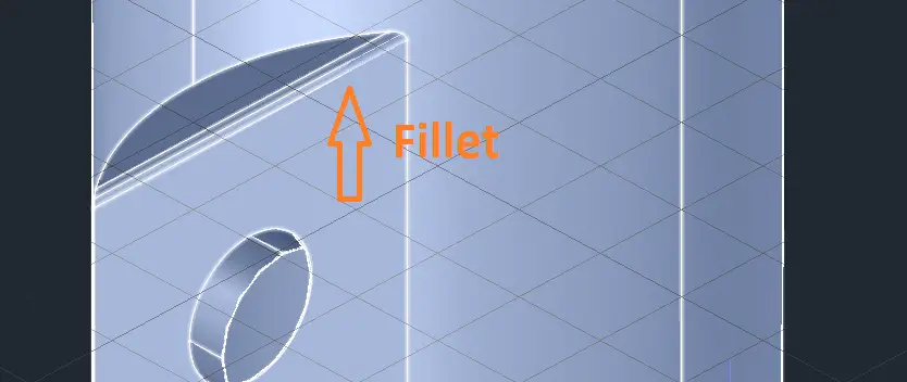
Next task is to fillet the side faces. Use the same command as in the previous step.
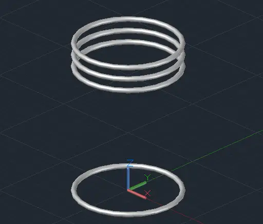
We will now create the ring pockets on the piston’s outer wall. Use the TORUS command. Set the center of the torus to the origin (0,0) and then use 60 units as the diameter and 3 units as the thickness. Make three copies of the torus (using the COPY command) with the following values in the z-direction: 76, 83 and 90 units.
You should delete the first torus. Remember that you can isolate (hide) the main body for this step.
Finally, subtract the tori (plural of torus) from the main body. You should now have a 3D model that looks like the one at the beginning of this post.
For more drawings that you can use to practice your skills, be sure to check out my book!
If you have any questions you can also email me at viktor@cadmode.com and I’ll do my best to help you out.
Do you have any tips to help make this tutorial easier? Did you find this tutorial helpful? Leave a comment! And please share the knowledge using the Share buttons below!
Are your drawings bloated for no obvious reason? When you insert a block, is there a long list of blocks that aren’t in the drawing? Ditto for layers?
Oversized drawings load more slowly, take up more storage space, and take longer to save.
Then you need the PURGE command!
Yes, you want slim drawings
Definitions of blocks, layers, styles, and more that aren’t actually used in the drawing make it slow and cumbersome. The PURGE command finds named components that aren’t used and lets you delete them. In a complicated drawing, there can be dozens or even hundreds of unused layers, blocks, text styles, dimension styles, and more.
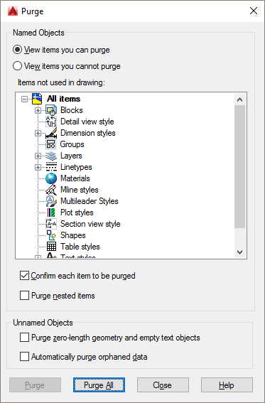
To start the PURGE command, choose Application Button, Drawing Utilities, Purge or just type purge on the command line. The Purge dialog box opens. Components that have unused items have a plus sign next to them. In this figure, you can see that there are unused blocks, dimension styles, layers, and linetypes. You can expand these items to see what you can purge.
This is a guest blog post by Jaiprakash Pandey, who is a CAD Corporate Trainer specializing in AutoCAD, CATIA and other CAD software’s. He is an Autodesk AutoCAD Certified professional and an Autodesk expert elite. He is a regular contributor to AUGI World magazine and he has also developed AutoCAD video courses for pluralsight, his own platform SourceCAD, and other E-Learning businesses. Explore more AutoCAD tutorials on his blog, SourceCAD.
* * * * *
With AutoCAD, you can create a short animated walkthrough video of your architectural model that can help you in presenting your ideas in a more creative way. Using short animated walkthroughs you can simply convey a lot of information without using many tools or drawings and even a non-technical person will be able to understand your design ideas.
This is a guest post by Khwaja Ibrahim. He is a Mechanical Engineer by profession and a CAD Engineer from Pakistan. His services range from designing for 3D Printing, Sheet Metal, Injection Molding and Manufacturing processes to providing Photo-Realistic Rendered Images.
He gets the utmost satisfaction in bringing ideas to life allowing him to demonstrate his creativity, designing and imaginative skills. As you can see, he also writes tutorials. This one is from 12CAD.com
By default design, AutoCAD’s line is a single entity. This singularity of the line allows it to be treated as a simple drawing element without the leverage of more complex types. However, for those of you who may require such a feature, there is a way other than grouping different colored lines into one.
As said, by default the line is a simple element hence to replicate functionality not built-in, we need to setup the proper environment before we proceed with the actual development. See the below screenshots for a step by step explanation of the prerequisites of sawing multicolored lines.
Preparation
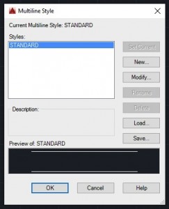
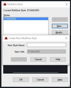
Step 1: Command: MLSTYLE. Use the command MLSTYLE to access the Multi-Style menu. When you press enter, the dialogue box should open up.
Step 2: View current profiles
By default a “Standard” profile is defined for regular line drawing. This is also set to the current profile in selection. At any time, this one profile will be available if there are no other. Create a new profile as shown below.Step 3: Create a new Multi-Style profileContinue reading How to create multicolored lines in AutoCAD
This is a guest post by AutoCAD expert Edwin Prakoso. You can find this and other AutoCAD tips on his website here.Edwin Prakoso works as an Application Engineer in Jakarta, Indonesia. He’s been using AutoCAD since R14 and Revit since Revit Building 9. He occasionally writes for AUGIWorld magazine and is also active in the Autodesk discussion forum. He’s an Autodesk Expert Elite, certified as Revit Architecture 2014 and an AutoCAD 2014 certified professional.
One common question that I get is how to access AutoCAD commands quickly.
AutoCAD is 30-year-old software. People used it before it ran on Windows. It was designed to run on different operating systems and different standard interfaces that are used today. That’s why there are many methods to access AutoCAD commands. One method may be faster in general, but another method can be faster when doing other tasks.
For example the command line is faster for most AutoCAD users for activating a line command. But Function keys are faster to toggle Ortho mode. It would be better for you to know all methods, so you can decide which one works best for you.
So let’s explore all the methods that you can use to execute AutoCAD commands and see how you can use them effectively.
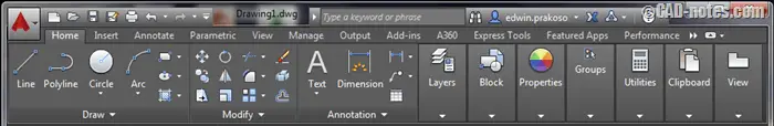
1. Ribbon
The ribbon was introduced in AutoCAD 2009. If you learn AutoCAD after this version, you probably use this as primary method. I found that many occasional users also like ribbon.
Many AutoCAD veterans don’t like ribbon, because it’s a big change from toolbar to ribbon. It feels slow (personally I feel it becomes better in later version) and take too much screen real estate.
This is the most apparent way to activate a command in latest version. Even if you’ve never seen AutoCAD in your entire life, you know you can activate a command from here.
Important: While we don't collect cookies, some of our 3rd-party services (such as PayPal and WordPress) do, to give you a safer and better browsing experience. Read about how we use cookies and keep your personal information secure by reading our Privacy Policy here.