Tool palettes are a great way to store blocks and hatches for easy access when needed. But if you have only one instance of each block or hatch, you may find that the scale isn’t right and the block or hatch comes in at the wrong size.
For example, you may need to change the scale of a hatch based on the plot scale you’ll be using. You would set the plot scale in the Plot dialog box.
And some blocks are used in dimensions or other annotation, and you may change the dimension scale for a dimension style, which you do on the Fit tab of the Modify Dimension Style dialog box. You may want the block to match that scale.
You could create a tool of the block or hatch at each of the sizes you use, but that might be overkill. Instead, you can automatically match the scale to the scale you’re using in your drawing. Here’s how:
Find the block or hatch on the tool palette.
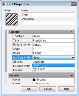
Right-click the block or hatch and choose Properties.
Click the Auxiliary Scale item to display the drop-down list.
Choose Dimscale to change the dimension scale or Plot scale to change the plot scale.
Click OK.
Now, your block or hatch automatically scales to your dimension or plot scale.
Sometimes, you need a more precise tool to select objects. AutoCAD’s most full-featured tool for selection is the FILTER command. The filter command has 3 advantages:
You can create very complex filtering parameters, using relational operators
You can group multiple filters
You can save filters
Create a single filter
To create a single filter, follow these steps:
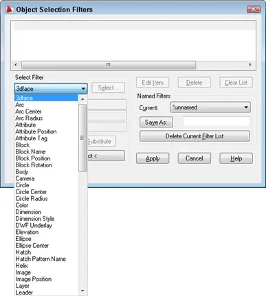
Type filter on the command line. If you’re in the middle of a command, type ‘filter to start the command transparently. The Object Selection Filters dialog box opens.
Click the drop-down list in the Select Filter section of the dialog box to display the available objects, properties, object snaps (such as Line End and Line Start), and logical operators. You use the logical operators to combine filters.
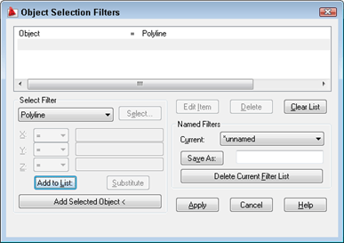
Choose the item that want from the drop-down list and click Add to List. You now see the item in the top pane. This filter you see here selects all polylines.
Repeat to add other criteria, clicking Add to List each time. Some filters need a value, which you can supply in 2 ways:
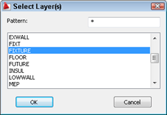
You can choose from a list. For example, you can choose Layer. Then click the Select button to open the Select Layer(s) dialog box, where you can choose from the layers that exist in the drawing.
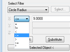
You can enter a value. For example, you can choose Circle Radius. Depending on which item you choose, one or more of the X, Y, and Z boxes become available. When you need only one value, use the X box. Then choose one of the relational operators from the drop-down list, as shown in the table. Here, I set the Circle Radius item to be less than or equal to 9.0000.
Here are your choices for operators that you can use when you need to specify a value.
Relational Operator
Description
=
Equal to
!=
Not equal to
<
Less than
<=
Less than or equal to
>
Greater than
>=
Greater than or equal to
*
Equal to any value
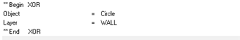
Note: As you add filters, AutoCAD assumes the AND operator, meaning that the selection needs to meet all of the criteria you specified. So, the following filter finds circles on the WALL layer whose radius is less than or equal to 9.0000.
Circle Radius <= 9.0000 Layer = WALL Object = Circle
Save your filter, in case you didn’t get it right or may need it again. Enter a name in the Save As text box and click the Save As button.
To correct a filter item, click it in the top pane and click Delete, or Edit Item. You can also click Clear List to start over.
When you’re done, click the Apply button.
The dialog box closes and you see the Select objects: prompt. This allows you to specify the objects that you want to filter. You can type all and press Enter, or specify a window. AutoCAD selects the objects you specified in the filter.
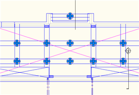
If you didn’t start a command, you can start one now and use the Previous option to select the objects defined by the filter. Here you see the circles on the WALL layer with radius less than or equal to 9.0000 selected.
Create multiple filters
The previous example uses multiple filters with the default AND logical operator. However, you can combine filter criteria using the following logical operators:
Operator
Description
Example
AND
Objects that meet all criteria
Circles on the WALL layer
OR
Objects that meet any of the criteria
All circles and all objects on the WALL layer
XOR
Objects that meet one or the other criteria, but not both
Circles not on the WALL layer and non-circles on the WALL layer
NOT
Objects that don’t meet the criteria
If applied to the Object=Circle criterion, objects on the WALL layer that are not circles
For example, to find objects that are not circles on the WALL layer and circles not on the WALL layer, follow these steps:
From the Select Filter drop-down list, choose BEGIN XOR and click Add to List.
From the Select Filter drop-down list, choose Circle and click Add to List.
From the Select Filter drop-down list, choose Layer. Click the Select button and choose the WALL layer. Click OK. Click Add to List.
From the Select Filter drop-down list, choose END XOR and click Add to List.
The result is shown here.
Note: The XOR logical operator must enclose 2 criteria. The NOT logical operator must enclose only 1 criterion, the one that you don’t want to include in the selection.
Continue to add criteria as described.
Save the filter as previously described.
Click Apply.
The dialog box closes and you see the Select objects: prompt. This allows you to specify the objects that you want to filter. You can type all and press Enter, or specify a window.
The Properties palette (Ctrl+1) is a great place to edit objects in many cases. When you double-click most objects, the Properties palette opens so that you can edit them. (Starting in AutoCAD 2012, the Quick Properties window opens instead.)
Note: There are exceptions, however. For example, if you double-click a polyline, the PEDIT command starts. You can use the CUI command to change what happens when you double-click an object.
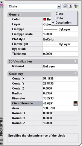
When you make changes in the Properties palette, you can undo those changes by clicking the Undo button on the Standard (or Standard Annotation) toolbar. But that’s a separate step in a different location; more importantly, it undoes all the changes you made in the Properties palette. Instead, you can undo edits, one by one, directly in the Properties palette.
After making a number of changes, right-click in any free (unused) section of the Properties palette, as you see here. Any of the margins around the edge are fine. Then click Undo as many times as you want.
We select objects all of the time, but most of us stick with a small number of familiar ways to select objects, and forget the rest. Perhaps it’s worthwhile to review all of the ways to select objects and learn some selection tips at the same time.
When you start an editing command, such as MOVE, you see the Select objects: prompt on the command line. But AutoCAD doesn’t show you any of your options.
Tip #1: At the Select objects: prompt, enter any nonsense, such as xx and press Enter to get this prompt:
Expects a point or Window/Last/Crossing/BOX/ALL/Fence/WPolygon/CPolygon/Group/Add/Remove/ Multiple /Previous/Undo/AUto/SIngle/SUbobject/Object
Now you can see all of your selection options! (Thanks to Leonid Nemirovsky for this tip.)
Here are the options, their shortcut, and how they work:
Selection Option
Keyboard Shortcut
Use
Window
W
Pick 2 diagonal corners. Everything completely inside the window is selected.*
Last
L
Selects that last object you drew in the current space (model or paper) whose layer isn’t off or frozen.
Crossing
C
Pick 2 diagonal corners. Everything completely or partially inside the window is selected.*
BOX
BOX
Combines Window and Crossing: If you pick the corners from left to right, you get the Window option; if you pick from right to left, you get the Crossing option. This is the default for Implied Windowing.
ALL
ALL
Selects all objects on layers that are thawed andunlocked.
Fence
F
Pick a series of points to define temporary line segments and select any object that crosses the lines.
WPolygon
WP
Like Window, but you pick more than 2 points, defining a polygon. Selects everything completely within the polygon.
CPolygon
CP
Like Crossing, but you pick more than 2 points, defining a polygon. Selects everything completely or partially within the polygon.
Group
G
Selects a named group of objects that you define with the GROUP command.
Add
A
Sets the selection mode to add objects to the selection set. This is the default; you’d use this after using the Remove option.**
Remove
R
Sets the selection mode to remove objects from the selection set. After using this option, any object that you specify is deselected.***
Multiple
M
Turns off highlighting as you select objects; you can’t preview which objects are in the selection set. (This old option had value when computers were slower than they are today and highlighting took time.)
Previous
P
Selects all objecst that you selected for the previous command’s Select objects: prompt.
Undo
U
Deselects objects select at the last Select objects: prompt.
AUto
AU
Combines picking objects with the BOX option. This is the default in implied windowing.
SIngle
SI
Ends the selection process after one selection process, without you pressing Enter.
SUbobject
SU
Selects vertices, edges, and faces of 3D objects.
Object
O
Ends subobject selection.
You may sometimes see a CLass option, which lets you select objects created in another application, such as Autodesk Map, that can add a classification to an object. You can then select objects by their classification property.
Implied windowing is active by default and is equivalent to the AUto option, which includes picking objects (clicking them directly) and the BOX option.
*Tip #2: While specifying a window or a crossing window, you can drag past the edge of the viewport (or screen if you have only 1 viewport displayed). AutoCAD pans the display to that you can see objects that were previously not visible. You can then specify the second corner of the window.
**Tip#3: You can press Ctrl+A to select all objects, but this cancels the command. You could then repeat the command and use the Previous option.
***Tip#4: Instead of using the Remove option, you can press Shift and use implied windowing to specify the objects to remove.
Tip#5: If you have many objects close together, at the Select objects: prompt, place the cursor over the area where objects overlap. Then press and hold the Shift key and press the Spacebar. Continue to press the Spacebar (with the Shift key down) to highlight one object after another, until you have the one you want. Then you can pick it.
You can turn off layers to make objects easier to select. For example, you might want to select only text; this will be easier if you turn off all other layers. The LAYISO command makes this easy. Start the command. At the prompt, use the Settings option and choose the Off suboption. Then select objects on layers that you don’t want to turn them off.
Another method to facilitate selection by layers is to create a layer filter to display only the objects on the layers that you need to select.
The QSELECT command and the FILTER command are other ways to filter objects according to their properties and select them.
In my earlier “Break objects quickly” tip, I have 4 routines that help you break objects more quickly than the standard AutoCAD command.
Febien Mosen sent me another routine, SCISSORS, that has 3 features:
You don’t need to preselect the object; you just click the point where you want to break
Only if there are more than 1 object under the break point (that is, if you click on the intersection of objects), does the command as you to select which object you want to break
;;first, get the breaking point (setq pt1 (getpoint “Give me the break point… “)) ;;point where to break
;;now, check if there’s more than one object under that point (setq ss1 (selectfrompoint pt1))
;;if there’s more than 1 object under point, ask to select, else use existing point (if (> (sslength ss1) 1) (progn ;;then (princ “DISAMBIGUATION : pick the object to break…”) (setq ent1 (entsel)) (setq ent1n (car ent1)) ;; e-name of ent1 (setq bpt1 (cadr ent1)) ;; point on ent to break ) (progn ;;else (setq ent1n (ssname ss1 0));;store into an entity (can be useful further) (setq bpt1 pt1) ;; point on ent to break ) )
;;but if it’s a circle (thus usually unbreakable)… (if (= (cdr (assoc 0 (entget ent1n))) “CIRCLE”) ;;then replace the circle by 2 arcs joining at the break point (progn (princ “It’s a circle !”) (setq centrecercle (cdr (assoc 10 (entget ent1n)))) (command “_arc” “_c” centrecercle pt1 “_a” “180”) (command “_arc” “_c” centrecercle pt1 “_a” “-180”) (entdel ent1n) ) ;;else perform a normal break (progn (command “_break” bpt1 “_f” pt1 pt1) ) )
;;— this function makes a selection set of entities beneath a point (defun selectfrompoint (bpt1 / dist1 ss1) (setq dist1 (/ (getvar “viewsize”) 200)) ;; set a distance equal to 1/200-th of view height (setq ss1 ;;select by fence around point (ssget “_F” (list (list (+ (car bpt1) dist1) (+ (cadr bpt1) dist1) 0) (list (- (car bpt1) dist1) (- (cadr bpt1) dist1) 0) ) ) );; setq ss1 ss1 )
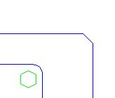
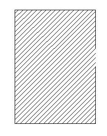
The CHAMFER command makes mitered (angled) corners, like the one below.
However, you can also use the CHAMFER command to extend lines to meet and make right-angled corners. In other words, you can use the command to turn the situation on the left to the situation on the right.
You do this by setting the Distance and Angle options to zero.
When you start the command, it lists the current settings:
Command: _chamfer (TRIM mode) Current chamfer Length = 1.0000, Angle = 45 Select first line or [Undo/Polyline/Distance/Angle/Trim/mEthod/Multiple]:
In this example the Distance option (which shows as Length) is 1 unit, and the angle is 45°. To create a square corner, use the Distance option and set both distances to 0. (You can specify a chamfer with two distances, rather than with a distance and an angle.) Then use the Angle option and set its value to 0. Then select both lines near their endpoints to get a square corner.
But that’s a lot of setting. Instead, you can quickly and temporarily override any non-zero settings by selecting the first line, and then pressing Shift as you select the second line. Presto! Instant square corners.
You could also use the EXTEND command (or the TRIM command with the Shift key), but the CHAMFER command is faster.
When you create a block in a drawing, you should think if it will be useful in other drawings.
You can access that block from other drawings using the DesignCenter or Content Explorer, but you’ll probably need to remember where the block was, in order to find it.
Instead, many people create block libraries, putting several blocks in a special block library drawing, or putting each block in a separate drawing. Because you name and store these drawings specially to make them easy to find and identify, the blocks they contain are easier to find.
For example, you may have a folder named Blocks. And you could name a drawing with a double-hung window block in it Double-Hung Window. That certainly helps you to find it!
To save a block in your drawing as a separate file, you use the WBLOCK command. This is called writing (saving) the block. Follow these steps:
Select the block that you want to write. (This saves you from having to find it in the drop-down list of all the blocks in your drawing when you open the Write Block dialog box.)
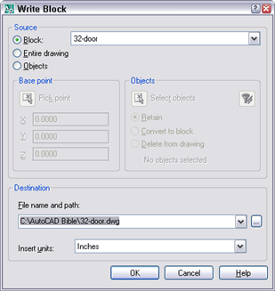
Type wblock on the command line. The Write Block dialog box opens.
In the Source section, choose Block. Your selected block appears in the drop-down list.
Click the Ellipsis button to navigate to the desired location and enter the desired drawing name in the File Name text box. Click Save.
In the Insert Units drop-down list, choose a unit type, if desired.
Click OK.
How do you keep track of drawings and create a block library? Leave a comment!
Gaps can be frustrating. You want to hatch an almost-closed object, but it doesn’t work. You may want to join lines, or close an arc or an elliptical arc to remove the gap. Finally, you may want to join polylines. Here are some tips about dealing with gaps.
First, and foremost, if you don’t want surprise gaps while you draw, always use object snaps when drawing. If you need to draw to the endpoint of a line, don’t eyeball it, use the Endpoint object snap.
Hatching
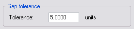
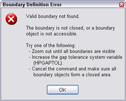
If you need to hatch an open area, use the DIST command to find out the length of the break. Then start the HATCH command. If you don’t see the Gap Tolerance section, click the right-facing arrow at the lower-right corner of the Hatch and Gradient dialog box. This section controls the HPGAPTOL system variable, which you can also specify on the command line. In AutoCAD releases with the Hatch Creation tab, click the Option panel’s drop-down arrow to find this setting.
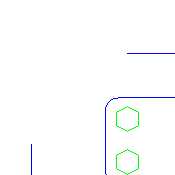
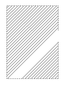
Enter a number larger than the gap. Then place the hatch by clicking the Add: Select Objects or Add: Pick Points button. However, these two methods of placing the hatch don’t always work the same way. Sometimes one button won’t work at all or won’t give the right results. In this example, only picking points worked properly.
By selecting objects
By picking points
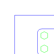
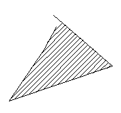
However, in the example below, selecting objects gave acceptable results, picking points displayed this dialog box and wouldn’t hatch at all.
Therefore, before giving up, try both options! Also, in some cases, you can fill with a regular hatch, but not with a solid.
Joining objects
You can use the JOIN command to eliminate gaps. The command requires lines, polylines, arcs, or elliptical arcs. (However, it combines splines and helixes if they touch each other, but are separate objects). Although AutoCAD’s Help on this command doesn’t explain this, the objects must be on the same linear, circular, or elliptical path. Therefore, JOIN works best for objects that you broke with the BREAK command and were therefore once one object.
A nice feature of JOIN is that you can close arcs to make circles and elliptical arcs to make ellipses.
Joining polylines
The PEDIT command has its own Join option. Start the PEDIT command and at the first prompt, choose the Multiple option and select both objects. Then use the Join option. At the Enter fuzz distance or [Jointype] <5.0000>: prompt, enter a number larger than the gap to close it, and end the command.
Use the Jointype suboption to specify how the gap is closed. The Extend method extends or trims segments to the nearest endpoints. The Add method adds a straight segment between the two nearest endpoints. The Both method tries to extend or trim, but if it can’t, adds a segment.
You’re drawing merrily along and you want to draw a line to a point, but you have OSNAP on, so the line keeps on snapping to the nearest endpoint. That’s not what you want! So you turn off OSNAP, but for the next line segment, you need it on again. So you turn it on.
There’s an easier way; you can use a temporary override. Temporary overrides are keyboard shortcuts that you press and hold to override a setting such as OSNAP, ORTHO, and more. Sometimes they’re a little awkward to use (you may feel as if you need an extra finger or two), but they’re so useful, you won’t mind.
Note that the overrides all use Shift and most have two, one for the left Shift key and one for the right key. Most people, having the mouse in their right hand, will use the first set with the left Shift key. But those of you who put your mouse in your left hand need not feel left out!
Here they are.
OSNAP on/off: Shift+A; Shift + ‘
ORTHO on/off: Shift
Object snap tracking on/off: Shift+Q; Shift+]
OSNAP and object snap tracking on/off: Shift+D; Shift+L (turns them both on or off)
Endpoint OSNAP: Shift+E; Shift+P
Midpoint OSNAP: Shift+V; Shift+M
Center OSNAP: Shift+C; Shift+,
There’s one more. Instead of working with OSNAP on and toggling it off temporarily, you could work with it off and toggle it on. The override above doesn’t do that. Instead, use Shift+S; Shift+;
One of the advantages of blocks is that you can substitute one for another. Why would you do that?
Your organization switches to a different part
You need to create more than one version of a drawing, each with a different part
If you use blocks for this purpose, think how much faster it would be to substitute the block instead of deleting the existing blocks and reinserting new ones for each instance!
In order for this to work, you need a file that contains only the new block that you want to use. If the block’s base point isn’t at 0,0, use the BASE command in that drawing and set the base point to the base point you want to use for the block, perhaps somewhere on the block.
Follow these steps:
Type -insert on the command line.
Type blockname=filename, where blockname is the name of the current block in your drawing and filename is the name of the file containing the new block you want to use. (If the file isn’t in the support file search path, type its path.) Press Enter.
At the prompt asking if you want to redefine the block (the current one in the drawing), type y and press Enter.
Press Esc to avoid inserting a new copy of the file. The file that you specified replaces all instances of the current block.
If you think that you might need to replace certain components in your drawing, make blocks out of them so that you can use this technique.
Remember, however, that you now have a block in your drawing that has the same name as before but is actually defined as something different, based on the file you specified. For example, you could have a block, circle, that is defined as square.
Express Tools has a command, BLOCKREPLACE, that you can also use to substitute blocks.
Important: While we don't collect cookies, some of our 3rd-party services (such as PayPal and WordPress) do, to give you a safer and better browsing experience. Read about how we use cookies and keep your personal information secure by reading our Privacy Policy here.