A region is an interesting type of AutoCAD object. You can think of it as a 2D surface. Regions are always closed and they look like polylines, but AutoCAD can do some interesting things with regions, such as:
Calculate centroid, moments of inertia, and products of inertia
Extrude them to create 3D solids
Combine (UNION command), subtract, and intersect them to create complex shapes
Follow these steps to create a region:
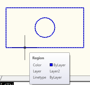
Draw objects that create a closed area. You can use closed polylines, closed splines, circles, ellipses, and a combination of lines, arcs, and elliptical arcs. The objects cannot intersect (like a figure 8). Here’s a simple example:
Objects for a region
If you want to keep your original objects (and create new regions, rather than converting the original objects to regions), type delobj on the command line. At the Enter new value for DELOBJ <1>: prompt, enter 0.
Start the REGION command.
At the Select objects: prompt, select all of the objects (including any internal objects, such as the circle inside the rectangle in the image you see here). End selection.
To subtract the circle from the rectangle, start the SUBTRACT command. At the Select solids, surfaces, and regions to subtract from .. Select objects: prompt, select the outer object, in this example, the rectangle. End selection.
At the Select solids, surfaces, and regions to subtract .. Select objects: prompt, select the inner objects, in this case, the circle. End selection.
AutoCAD creates one object, which is a rectangular 2D region with a hole in it.
Sometimes you need to create a closed polyline from several existing objects that don’t meet end to end.For example, let’s say that you want to draw a polyline from the inside border created by the rectangle and two circles.
The BOUNDARY command is a very easy way to do this.
Start the BOUNDARY command to open the Boundary Creation dialog box. Notice that the default object type is Polyline. You can also choose to create a region. Click the Pick Points button and click inside the closed boundary. Press Enter and you’re done!
Watch the video.
Note: If the objects do meet end to end, you can start the PEDIT command. At the Convert Lines, Arcs and Splines to polylines [Yes/No]? prompt, use the Yes option.
At the Enter an option [Close/Open/Join/Width/Fit/Spline/Decurve/Ltype gen/Reverse/Undo]: prompt, use the Join option to join the individual polylines into one.
Some coordinates are easy to find. For example, to find the endpoint of a line, you just use the Endpoint object snap.
But others are more elusive.
For example, recently someone asked me, “I would like to ask if there is a simple way to select a center of a rectangle.”
My answer was: If you press Shift and right-click, you’ll get the OSNAP menu. Choose Mid Between 2 Points, and choose two diagonal corners.
Finding coordinates is a very common task, so here are some other tips for specifying hard-to-find coordinates.
Polar coordinates
To find a point at a specific angle, use polar coordinates, in the format distance<angle. So, to draw a line that is 3.5 units at a 15°, enter 3.5<15.
Apparent Intersection OSNAP
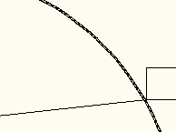
The Apparent Intersection object finds an intersection that would be created if you extended two objects until they met. It’s very simple to use. You start a command, such as the LINE command, specify the OSNAP (you can type app), specify a first point, such as an Endpoint, then hover over the second point. You’ll see an X at the apparent intersection. Just click to lock in the coordinate.
Watch the video.
Extension OSNAP
The Extension object extends lines and arcs in the same direction, past their endpoints. Look for the Extension tooltip; at the same time you’ll see a temporary extension path.
Watch the video.
Object snap tracking
Object snap tracking lets you specify a point based on object snaps of existing objects. When you’re looking for the intersection of two existing endpoints, it works similarly to the Apparent Intersection OSNAP. But it has more uses that that. For example:
Your want the endpoint of a line you’re drawing to be vertical to the endpoint of an existing line.
You want to center a circle inside a rectangle
You want to start a line where two existing lines would intersect if they extended (you can do this with the Apparent Intersection object snap, too)
Note that you can use object snap tracking with polar snapping, so the angles don’t have to be orthogonal.
Follow these steps:
Turn on at least one running object snap. To do so, right-click the Object Snap (OSNAP) button on the status bar and choose an object snap, or choose Settings first (depending on your version).
Click the Object Snap Tracking button on the status bar (which is different from the Object Snap button). to turn on this feature.
Start a drawing command that requires you to specify a point.
Hover the cursor over an object snap, to acquire that point. You see a small plus sign at the object snap point.
If necessary, acquire a second point.
Move the cursor toward the coordinate you want to locate until you see one or two temporary, dotted alignment paths. You’ll also see one or two tooltips and an X.
Click to specify the point. Then continue the command you started..
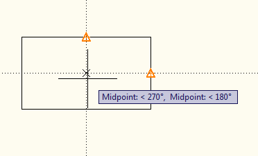
Here, I started the CIRCLE command and acquired the midpoints of the two sides of the rectangle to find its center. This specifies the center of the circle at the center of the rectangle
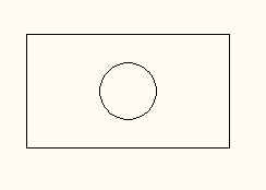
Here’s the result:
Temporary tracking
You can also use temporary tracking to accomplish the same result, as long as the angles are orthogonal. Follow these steps:
Turn on at least one running object snap. To do so, right-click the Object Snap(OSNAP) button on the status bar and choose an object snap, or choose Settings first (depending on your version).
Start a drawing command that requires you to specify a point
Type tk and press Enter.
At the First Tracking point: prompt, specify an object snap by clicking it. It must be horizontal or vertical to the final point that you want to specify.
Move the cursor horizontally or vertically toward the desired coordinate. You see a solid, temporary rubber-band line.
At the Next point: prompt, move the cursor from the rubber-band line to the second object snap, and click.
Press Enter to end tracking and continue the command.
Point filters
Point filters are the original way to specify coordinates that aren’t on an object, based on object snaps of existing objects. Most people use object snap tracking now, but they can still be useful, especially in 3D work. You build an X,Y (or X,Y,Z) coordinate by using the X coordinate of one object snap, the Y of another, and perhaps a Z of another.
Follow these steps:
Start a drawing command that requires you to specify a point.
Type .x or .y and press Enter. (You can also Shift + right-click to choose a point filter from the object snap menu.) Let’s say I start by typing .x.
At the of (need YZ): prompt, use an object snap to specify the x coordinate of the desired coordinate. To continue the example of drawing a circle centered inside a rectangle, you would specify the midpoint one of the rectangle’s horizontal lines, because the x coordinate of the circle’s center should be the same as the x coordinate of the horizontal line’s midpoint.
Now, simply specify the object snap on an object to locate the y coordinate. In this example, specify the midpoint of one of the rectangle’s vertical lines.
AutoCAD locates the coordinate and you can continue the command.
From
From is a feature that lets you find coordinates off objects by specify the offset from an object snap. You can specify that offset as the x,y distance or polar coordinate notation.
Follow these steps:
Type from and press Enter. (You can also Shift + right-click and click From on the object snap menu.)
At the Base point: prompt, specify the base point with an object snap.
At the Offset: prompt, enter @ and relative x,y or polar coordinates. Note:You must use @ even if you are using a default of relative coordinates.
Continue the command.
Do you have other ways of locating hard-to-find coordinates? Leave a comment here.
Sometimes, you need text to have a specific line spacing, to fit into a schedule in your drawing. If you can use the TABLE command, that’s great, because the text automatically fits nicely into the rows of the table.
But sometimes, you need to fit your text into an existing set of lines, like a title block, or just want the lines of text to fit nicely into a certain space. In these instances, you should know how to specify line spacing for multiline text. By using multiline text, you can quickly enter many lines of text and place them exactly where you want.
Follow these steps to set the line spacing:
Start the MTEXT command.
At the Specify first corner: prompt, pick the first corner of the Mtext bounding box.
At the Specify opposite corner or [Height/Justify/Line spacing/Rotation/Style/Width/Columns]: prompt, don’t do what you usually do, which is specify the opposite corner. Instead. use the Line spacing option (you can type l).
At the Enter line spacing type [At least/Exactly] <At least>: prompt, use the Exactly option.
At the Enter line spacing factor or distance <1x>: prompt, enter the line spacing in units. The default, 1x, gives you single-line spacing, which varies with the side of the text. For text that is .5 units apart, enter .5
The Specify opposite corner or [Height/Justify/Line spacing/Rotation/Style/Width/Columns]: prompt returns, and now you specify the opposite corner.
Enter your text.
The MTEXT command doesn’t allow for easy placement, but once you have the text entered with the right line spacing, it’s easy to move. Now you’ll see the advantage of having all the text as one object; move it and all the lines of text move together.
Note that this setting persists for future MTEXT objects. To set the linespacing back to the default setting, at the Line spacing option, enter 1x. Then set the line spacing type to At Least.
You might not realize that you need to set line spacing until you’ve entered the text and seen that it doesn’t fit properly. In this case, you need to change the line spacing of the existing text. Follow these steps:
Select the multline text object.
Open the Properties palette.
Set the Line Space Distance item to the line spacing you want.
Some people prefer to learn from video, so I’ve created a video of a tutorial that I created on drawing a 3D threaded bolt. The video is 9 minutes long. You can find the text version at “Draw a 3D threaded bolt.”
You can use the Shift key in AutoCAD in many ways to help make your AutoCAD tasks easier and quicker:
Press Shift with the FILLET or CHAMFER command to change the radius to 0 and extend to lines to meet
Press and hold Shift to temporarily override ORTHO.
Press and hold Shift+A to temporarily override OSNAP.
Press Shift to change TRIM to EXTEND and vice versa.
Press Shift and pick objects to remove them from the current selection set. You can also press Shift and click a window or crossing selection.
If you have several objects that overlap at a point, mouse over that point, press Shift and press the Spacebar repeatedly to cycle through these objects
In the AutoCAD Text window (press F2 to open and close it), press SHIFT with a key to highlight text. For example, press Shift + Home to highlight text from the cursor to the beginning of the line. Or press Shift + the Up arrow to select the previous line of prompts.
Here are all the keyboard shortcuts I could find in AutoCAD’s Help that use Shift:
SHIFT+, Object Snap Override: Center
SHIFT+. Toggles Polar Tracking
SHIFT+/ Toggles UCSDETECT
SHIFT+; Enables Object Snap Enforcement
SHIFT+] Toggles Object Snap Tracking
SHIFT+C Object Snap Override: Center
SHIFT+D Disable All Snapping and Tracking
SHIFT+E Object Snap Override: Endpoint
SHIFT+L Disable All Snapping and Tracking
SHIFT+M Object Snap Override: Midpoint
SHIFT+P Object Snap Override: Endpoint
SHIFT+Q Toggles Object Snap Tracking
SHIFT+S Enables Object Snap Enforcement
SHIFT+V Object Snap Override: Midpoint
SHIFT+X Toggles Polar Tracking
SHIFT+Z Toggles UCSDETECT
Do you know of another Shift tip? Leave a comment.
Several people (Kent Elrod, Edwin Prakoso, Jon Groelz, W.S.Walker, Hans Graveman, Kevin Schaefer) mentioned Shift + right mouse button to display the OSNAP menu. Of course! That was probably the first Shift shortcut I ever used!
Several people (Kent Elrod, Edwin Prakoso, W.S.Walker, Susan Lafleur) mentioned Shift + middle mouse button (usually the scroll wheel) to transparently go into 3D orbit. Another good one! I use that a lot when I’m working in 3D.
Several people (Kent Elrod, Rusty Gesner, Gary Ketter) mentioned pressing Shift and clicking multiple grips, to select them.
Bill Northrup mentioned two great ones, which work well together:
Ctrl+Shift+C: This is the COPYBASE command. It copies a selected object, prompting you for the base point.
Ctrl+Shift+V: This is the PASTEBLOCK command. It pastes an object that you copied to the clipboard as a block. (AutoCAD assigns it a name.)
A couple of people noted that you can set AutoCAD (on the Drafting tab of the Options dialog box) to require pressing the Shift key to acquire a point for tracking; it’s not the default setting, though. As a matter of fact, you can set AutoCAD (on the Selection tab of the Options dialog box) to require pressing the Shift key to select more than one object at a time (the way you do in most other programs).
Ken Monsanto of Bahrain Precast Concrete sent in this tip for scaling an object when you know the current and desired dimensions. For example, let’s say that you have a circle with a diameter of 35 and you want to scale it so that it has a diameter of 50.
He suggested these steps:
Start the CAL command.
Command: cal >> Expression: 50/35 1.42857143
Select the quotient 1.42857143 and copy it to the Clipboard.
Start the SCALE command, select the object, specify the base point, and click on the Command line. (If you don’t click on the Command line, AutoCAD thinks that you want to paste a text object into your drawing.)
Paste the quotient from the Clipboard and press Enter.
Your circle now has a diameter of 50.
Instead of the CAL command, you can use the newer QUICKCALC command and use the calculator-like interface.
CAL command
The advantage is that the command automatically copies the result to the Clipboard for you.
If you’re scaling a circle, and you know the radius (or dividing by two is easy), here’s an easier method. This method works in AutoCAD 2006 and later. Follow these steps:
Select the circle.
Click one of the quadrant handles and drag inward or outward.
Type the new radius and press Enter.
For other techniques of changing a circle’s size, see the first tip below.
You can put an AutoCAD drawing — in DWF format — directly into PowerPoint. Not just a JPEG or other image of the drawing, but the actual drawing. More incredible, with Autodesk® Design Review, you can zoom in and out and pan around the drawing to show all of the drawing in detail, all from within your PowerPoint presentation. To get the latest version, go to www.autodesk.com/designreview.
These instructions are updated for AutoCAD 2008 and PowerPoint 2007. The instructions are quite different, because PowerPoint 2007 requires a different procedure.
Here are the steps:
Make sure you have Autodesk Design Review on the computers you use to create and deliver your presentation. In PowerPoint, display the slide where you want to put the drawing.
In PowerPoint 2007 only, make sure that the Developer tab is displayed. (It’s not displayed by default.) Choose Office button>PowerPoint Options>Popular, and check the Show Developer Tab in the Ribbon check box.
PowerPoint 2007 may block ActiveX content. In PowerPoint 2007 only, choose Office button>PowerPoint Options>Trust Center>Trust Center Settings button>ActiveX Settings, and make sure that the Disable All Controls without Notification option is not selected. Instead, choose the third option, Prompt Me before Enabling All Controls with Minimal Restrictions.
In PowerPoint 2003, right-click any toolbar and choose Control Toolbox to display that toolbar. Then click the More Controls button. In PowerPoint 2007, choose Developer tab>Controls group>More Controls.
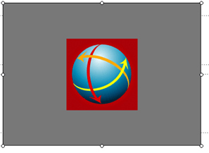
From the list that appears, choose Autodesk DWF Viewer Control. (In PowerPoint 2007 only, click OK.) Drag diagonally on the slide to specify a bounding box for the AutoCAD drawing. You now see the Autodesk Design Review logo on the slide.
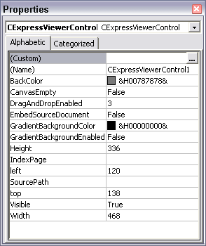
Right-click the rectangle and choose Properties to open the Properties window.
Click the Custom item and then click the Ellipsis button that appears to display the Property Pages dialog box
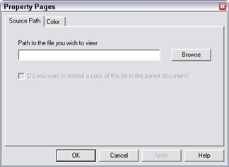
On the Source Path tab, click Browse and browse to the DWF file. Double-click the file. To embed the DWF in the PowerPoint presentation (a good idea if you’ll be viewing it on another computer or want to send it to someone), check the Do You Want to Embed a Copy… check box. You can also use the Color tab to change the color of the background. (Below you see a custom teal color.) Click OK to return to your presentation. Close the Properties window. You now see the drawing on the slide.
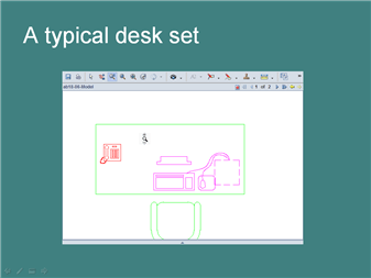
In PowerPoint, go into Slide Show view to view the slide. After a brief pause/adjustment (perhaps embarrassing in a presentation environment), you see the drawing, along with the Autodesk Design Review toolbar. Here you see the Zoom cursor.
From the toolbar, you can zoom, pan, print, mark up, and measure. Click the Show/Hide Navigator button on the toolbar to display the Navigator, where you can turn layers on and off (if this feature has been enabled), display named views, and more. You can also right-click to use the shortcut menu for many tasks. Other options may be available depending on how the drawing was saved.
This makes for a very nice presentation, zooming in and panning to show the drawing in detail. It’s certainly more than you can do with a JPEG.
Architects use sheet sets all the time to pull together the many required drawings into one package. Other disciplines use them less often, but if you need to deliver a number of drawings together, they can help you organize and maintain them.
Sheet sets have a reputation for being complicated and they are, if you use all of the features. But you can create a simple sheet set easily and you may find that they help you out a lot. For example, you can do the following with a sheet set:
Number them
Plot and publish them
Open them
eTransmit them
ZIP them
Top Customization Tips Every AutoCAD User Should Know
AutoCAD is meant to be customized, but customization is one of the most complex features of AutoCAD. Gain the knowledge you need to be a master at customizing AutoCAD!
A sheet set is a DST file that contains the properties of the sheet set. You start with drawings that have model space content; these are your resource drawings. One layout for each drawing becomes the sheet in the sheet set. Therefore, a sheet set is a collection of layouts, one for each drawing.
Follow these steps to create a simple sheet set:
In a folder where you normally save drawings, create a new subfolder and name it so that you’ll recognize the drawings that will be in the sheet set.
Create your drawings as normal and save them in the new folder. For easiest workflow, don’t put any other drawings in that folder.
Start a new drawing, because you need an open drawing to create a sheet set.
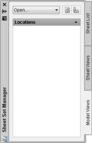
Choose View tab> Palettes panel> Sheet Set Manager or press Ctrl+4.
From the drop-down list at the top of the Sheet Set Manager (SSM), choose New Sheet Set to open the Create Sheet Set wizard.
Choose the Existing Drawings option and click Next.
Enter a name for the sheet set and a description. Notice that there’s a default location for the sheet set, which is a DST file. This will probably be in Documents\AutoCAD Sheet Sets. Use the default, or click the Ellipsis button to browse to another location that you want to use, and click Open. Click Next.
On the Choose Layouts page, click Browse, navigate to the folder where you saved the drawings for the sheet set, and click OK. You see the folder listed with a checked check mark. Click Next.
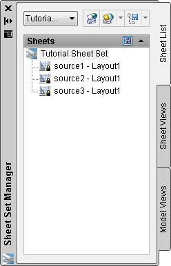
You now see a preview of the sheet set’s properties, including its name and location. Click Finish. You should see your new sheet set listed in the SSM on the Sheet List tab.
Click the Model Views tab of the SSM. Double-click the Add New Location text.
In the Browse for Folder dialog box, navigate to the folder containing the subfolder that has your drawings. Chose the folder and click Open. You are designating a folder location for the drawings that the sheet set will use.
If you haven’t already done so, you should create a layout that displays what you want to plot. To do so, on the Model Views tab, expand the folder if necessary. Then double-click the first drawing to open it. One task that the sheet set feature makes easy is opening multiple, related drawings.
Each drawing needs to have a saved layout. Click the Layout button on the status bar, or click the layout tab. (The SSM works best when you have only one layout per drawing.) Create the viewport(s) and views that you want, and save the drawing.
Do the same for all of the drawings.
Click the Sheet List tab. Now, you can add layouts as sheets in your sheet set. Right-click the name of the sheet set and choose Import Layout as Sheet. In the Import Layouts as Sheets dialog box, click Browse for Drawings. Choose the drawings you saved in the subfolder (click the first, press Shift, and click the last) and click Open. Click Import Checked to return to the SSM. Congratulations! You now have a sheet set.
To give the sheets numbers, right-click any sheet, and choose Rename & Renumber. You can then drag them on the Sheet List tab to reorder them.
To plot the sheets, select them on the Sheet List tab, click the Publish button’s down arrow, and choose Publish to Plotter.
To eTransmit them, right-click the name of the sheet set and choose eTransmit.
To ZIP them, right-click the name of the sheet set and choose Archive.
Throughout these steps, you’ll see various settings that I didn’t mention. Investigate them to get the exact results that you want. To specify properties for the entire sheet set, right-click its name on the Sheet List tab and choose Properties.
The advanced features of sheet sets help you to automatically number and annotate text in title blocks, callout blocks, and label blocks.
Important: While we don't collect cookies, some of our 3rd-party services (such as PayPal and WordPress) do, to give you a safer and better browsing experience. Read about how we use cookies and keep your personal information secure by reading our Privacy Policy here.