
A common, but difficult task, is to create a threaded bolt. I recently got a request for more 3D tutorials, so here you go. This tutorial assumes an intermediate knowledge of AutoCAD.
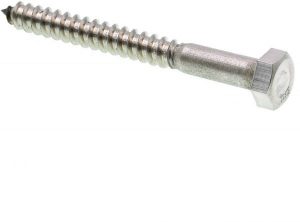
I rummaged around a box of miscellaneous junk and found this bolt. It’s about 3 inches long.
Follow these steps:
- Start a new drawing using acad3d.dwt as the template. Set the visual style to 3D Wireframe and the workspace to 3D Modeling.
- Type plan to see the view from the top.
- Create a new layer, object, and make it blue.
- Start the POLYLINE command, specify a start point anywhere in the middle of the screen, and draw segments as follows:
- 3<180
- 3/16<90
- .5<0
- 1/4,-1/16 (this will be a diagonal line whose delta X = 1/4 and delta Y = 1/16
- 2<0
- Close
Note: Close the polyline ensures that you’ll get a solid rather than a surface when you revolve. You’ll need the solid for later operations, such as UNION.


- Start the REVOLVE command and select the polyline. Revolve it along the 3-unit line, for the default 360 degrees.
- To get a fuller look, set the ISOLINES system variable to 8 and use the REGEN command.

- Just to see the result, switch to the SW isometric viewpoint.
- Then, switch to the Left viewpoint. You should be viewing the bolt from the top.
- Start the UCS command and use the View option to create a new UCS. If you want, save it.
- Return to the SW Isometric viewpoint again. You’re still in the new UCS. This will help you create the bolt’s head.
- Start the CYLINDER command. The center should be the center of the revolved solid’s top. Use the Diameter option and set it to 9/16. The height is 0.25.
- Create a polygon of 6 sides. The center is the bottom center of the cylinder, use the Circumscribe About Circle option. The radius = 9/32.
- Use the EXTRUDE command to extrude the hexagon to the top of the cylinder.
- To create the beveled top, draw a circle at the top of the cylinder, with the same 9/32 radius.
- Extrude it, using the Taper Angle option. The taper angle = -45 degrees, the distance is -0.5, to extrude it downward.
- Use the INTERSECT command and choose the extruded, tapered circle and the extruded hexagon, and you should see the familiar look of the head of a bolt. Here you see it in the Conceptual visual style.

- To create the threads, start the HELIX command. The center is the center of the circle at the top of the thread area. The base radius is any quadrant of the same circle. Press Enter to set the top radius to the same as the base radius. Use the Turns option and set the turns to 14. For the axis endpoint, pick the center at the bottom of the rod, before it tapers to a point.
- Switch to the World UCS and use the PLAN command. Turn the viewpoint so that the end of the helix is at the top or bottom. Below, you see it at the bottom. Use the UCS command with the View option.
- To create the triangular shape of the thread, start the POLYGON command and set it to 3 sides. Set the center to the endpoint at the end of the rod. Use the Inscribed in Circle option. Set the radius to 1/16. If the endpoint of the heliix is at the bottom, as you see here, you need to rotate the triangle 180 degrees. It should look like the figure here. The point of the triangle needs to be facing outward from the rod of the bolt.

- Start the SWEEP command and select the triangle. Use the Alignment option and set it to No. Then select the helix as the sweep path.
- Use the UNION command to combine all the objects. Here’s the result in the 3D Hidden visual style.

Here’s the result with the Framing Steel material. I expected it to be silver but it came out coppery. It looked so good that I left it.

For an excellent set of 3D tutorials, go to JD Mather’s site.
Related tips:
* Tutorial: Draw a 3D threaded bolt-video tutorial (See a video of this tutorial!)
* 3D Tutorial: Draw a glass
* Carve a solid with a surface
Draw and edit faster and easier with these top 25 productivity tips every AutoCAD user should know. Check out “Top Productivity Tips Every AutoCAD User Should Know” at http://www.ellenhelps.me/25-Productivity-Tips

- Combine or subtract 2D shapes to create custom shapes - February 17, 2022
- Working with linetype scales - January 18, 2022
- Rename named objects–blocks, dimension styles, layers, and more - December 21, 2021


[…] Some people prefer to learn from video, so I’ve created a video of a tutorial that I created on drawing a 3D threaded bolt. The video is 9 minutes long. You can find the text version at “Draw a 3D threaded bolt.” […]
Very useful, I appreciate the instructions.
Thank you very much for this. It looks awesome.
Probably everyone in the world has mentioned this, but that’s actually a lag screw, not a bolt. Bolts are designed to be used with nuts, although there’s some “definition bleed” where “machine screws” are concerned; they can be used in tapped holes OR used with nuts, just like a bolt.
If it’s made to screw into wood, though, it’s definitely NOT a bolt!
Your anal-retentive fan,
Mark
Mark, in the UK (I don’t know about the US) we call a wood screw with a hexagon head a “Coach Bolt”. However this is not important and does not detract from this very useful tutorial.
thank you.,,nice site
Thanks…..nice instructions..:)
thanks..
Hi i need help!!!,when i attempt to sweep 3-sided polygon after choosing non-alignment sweep option i get the unable to sweep object reply,any ideas why/,thanks.
What happens if you don’t choose the non-alignment option?
Sorry for late reply,i had to put screw shaft on a different layer to the helix turn it off,then sweep polygon & turn shaft back on then union & hey Presto,thanks anyway looks good!
The screw/bolt/lagbolt/lagscrew (geez who cares!) was an excellent choice for a 3D tutorial. I also watched the video as well. The biggest problem I have is being in the correct UCS! Thanks for the help.
thanks dude!
Really it is very useful but while doing the same i am not able to design properly… can you help me out with this please
thankyou ellen,you really tought nicely and i will surely seek for more help from you to be more perfect…
Worked first time although I used your methodology to draw a completely different “bolt”. Now I need to understand why my multiple attempts didn’t work even though the methodology was almost identical. In my version the trianglular thread form would always rotate 60deg whichever sweep options I used. I even tried to offset the rotation but I couldn’t fool it, it would just rotate a different amount.
Without seeing what you’re doing, I can’t know. Perhaps you can find some other tutorial that uses the same features to get some other information on it.
[…] Tutorial: Draw a 3D threaded bolt « AutoCAD Tips BlogJun 19, 2011 … A common, but difficult task, is to create a threaded bolt. I recently got a request for more 3D tutorials, so here you go. This tutorial assumes an … […]
I am drawing a screw for a conveyor. my cross section is not a triangle. It is more of a rectangle. 3 x 120 rectangle. my shaft has 25mm radius. when i tried to draw it like this it started acting really weird and gave some weird results. can u leave some instructions please.
I’m beginner and i watch your video Its very very useful and nice. Thank for your video.
I have the following questions:
1. I do not have acad3d.dwt, only acad.dwt, so how do I start the former???
2. How do I set visual style to 3D Wireframe and the workspace to 3D Modeling???
3. When I perform Step 4 of the Tutorial, I get a funny looking shape!
Please advise.
El tutorial es muy explicito y no tuve problema alguno para dibujar el tornillo.
Gracias y un cordial saludo.
Thank you so much, I’ve been trying ƭσ make screw threads for weeks, and with this, drew ɪt in a few seconds. Lovely page!
tnx a lot
thank you it is very useful for me. please tell me that there is any other way to draw thread by using only revolve comand. how to made internal thread in autocad
[…] There in more than one way to model a Threaded rod in AutoCAD, another way is to create a shape on a right form and add it to your cylinder, Ellen Finkelstein wrote about this. […]
Helpful
Thanks
SL
Useful tip. Thank you
wonderfull tutorial!
Nicely drawn with the front and side elevations designs. Perspective matter when doing 3D diagrams.
thanks ellen
thanks………………..this method is most helpful…..
3<180 please explain…which direction ect.???
hi eric
3<180 explain
3(length)<180(degres)
Thanks with your help i manage to draw a nut bolt and washers
hi Ellen, thanks for the nice tutorial. I have a problem though, in step 16, when I use ‘intersect’ command, the whole polygon below the extruded tapered circle is gone. I can’t have the result like yours.
What went wrong ?
how do you get a hexagon that’s 9/32 in radius to fit around a cylinder that’s 9/16 in radius, and the method you describe for adding the bevel simply doesn’t work.