
Some coordinates are easy to find. For example, to find the endpoint of a line, you just use the Endpoint object snap.
But others are more elusive.
For example, recently someone asked me, “I would like to ask if there is a simple way to select a center of a rectangle.”
My answer was: If you press Shift and right-click, you’ll get the OSNAP menu. Choose Mid Between 2 Points, and choose two diagonal corners.
Finding coordinates is a very common task, so here are some other tips for specifying hard-to-find coordinates.
Polar coordinates
To find a point at a specific angle, use polar coordinates, in the format distance<angle. So, to draw a line that is 3.5 units at a 15°, enter 3.5<15.
Apparent Intersection OSNAP
The Apparent Intersection object finds an intersection that would be created if you extended two objects until they met. It’s very simple to use. You start a command, such as the LINE command, specify the OSNAP (you can type app), specify a first point, such as an Endpoint, then hover over the second point. You’ll see an X at the apparent intersection. Just click to lock in the coordinate.
Watch the video.
Extension OSNAP
The Extension object extends lines and arcs in the same direction, past their endpoints. Look for the Extension tooltip; at the same time you’ll see a temporary extension path.
Watch the video.
Object snap tracking
Object snap tracking lets you specify a point based on object snaps of existing objects. When you’re looking for the intersection of two existing endpoints, it works similarly to the Apparent Intersection OSNAP. But it has more uses that that. For example:
- Your want the endpoint of a line you’re drawing to be vertical to the endpoint of an existing line.
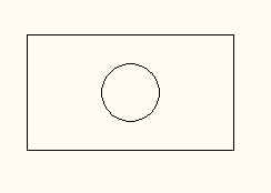
- You want to center a circle inside a rectangle
- You want to start a line where two existing lines would intersect if they extended (you can do this with the Apparent Intersection object snap, too)
Note that you can use object snap tracking with polar snapping, so the angles don’t have to be orthogonal.
Follow these steps:
- Turn on at least one running object snap. To do so, right-click the Object Snap (OSNAP) button on the status bar and choose an object snap, or choose Settings first (depending on your version).
- Click the Object Snap Tracking button on the status bar (which is different from the Object Snap button). to turn on this feature.
- Start a drawing command that requires you to specify a point.
- Hover the cursor over an object snap, to acquire that point. You see a small plus sign at the object snap point.
- If necessary, acquire a second point.
- Move the cursor toward the coordinate you want to locate until you see one or two temporary, dotted alignment paths. You’ll also see one or two tooltips and an X.
- Click to specify the point. Then continue the command you started..
Here, I started the CIRCLE command and acquired the midpoints of the two sides of the rectangle to find its center. This specifies the center of the circle at the center of the rectangle
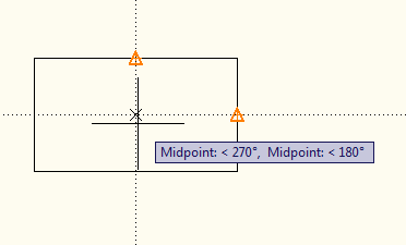
Here’s the result:
Temporary tracking
You can also use temporary tracking to accomplish the same result, as long as the angles are orthogonal. Follow these steps:
- Turn on at least one running object snap. To do so, right-click the Object Snap(OSNAP) button on the status bar and choose an object snap, or choose Settings first (depending on your version).
- Start a drawing command that requires you to specify a point
- Type tk and press Enter.
- At the First Tracking point: prompt, specify an object snap by clicking it. It must be horizontal or vertical to the final point that you want to specify.
- Move the cursor horizontally or vertically toward the desired coordinate. You see a solid, temporary rubber-band line.
- At the Next point: prompt, move the cursor from the rubber-band line to the second object snap, and click.
- Press Enter to end tracking and continue the command.
Point filters
Point filters are the original way to specify coordinates that aren’t on an object, based on object snaps of existing objects. Most people use object snap tracking now, but they can still be useful, especially in 3D work. You build an X,Y (or X,Y,Z) coordinate by using the X coordinate of one object snap, the Y of another, and perhaps a Z of another.
Follow these steps:
- Start a drawing command that requires you to specify a point.
- Type .x or .y and press Enter. (You can also Shift + right-click to choose a point filter from the object snap menu.) Let’s say I start by typing .x.
- At the of (need YZ): prompt, use an object snap to specify the x coordinate of the desired coordinate. To continue the example of drawing a circle centered inside a rectangle, you would specify the midpoint one of the rectangle’s horizontal lines, because the x coordinate of the circle’s center should be the same as the x coordinate of the horizontal line’s midpoint.
- Now, simply specify the object snap on an object to locate the y coordinate. In this example, specify the midpoint of one of the rectangle’s vertical lines.
- AutoCAD locates the coordinate and you can continue the command.
From
From is a feature that lets you find coordinates off objects by specify the offset from an object snap. You can specify that offset as the x,y distance or polar coordinate notation.
Follow these steps:
- Type from and press Enter. (You can also Shift + right-click and click From on the object snap menu.)
- At the Base point: prompt, specify the base point with an object snap.
- At the Offset: prompt, enter @ and relative x,y or polar coordinates. Note:You must use @ even if you are using a default of relative coordinates.
- Continue the command.
Do you have other ways of locating hard-to-find coordinates? Leave a comment here.

- Combine or subtract 2D shapes to create custom shapes - February 17, 2022
- Working with linetype scales - January 18, 2022
- Rename named objects–blocks, dimension styles, layers, and more - December 21, 2021


Ellen, great new blog! The layout is very nice, clean, easy to read, and follow. As always, looking forward to your future posts!
~Kevin
These Tips were very helpful and assisted me with a drawing of some runway PAPI LIGHTS which were rectangular in design.However,I now need to locate the PAPI LIGHTS 50′-0″ from the edge of the runway.Can Auto Cad give me values for each point of a rectangle in X and Y coordinates(northings and eastings).The PAPI LIGHTS are 3′-0″x 5′-0″.I need the coordinates to accurately set out the PAPI LIGHTS and thier cylindrical conduit cans.Thank you for all the tips you have given.
Can Auto Cad give me values for each point of a rectangle in X and Y coordinates
Kevin,
Thanks, I’m really glad to finally get this done!
Ellen
Desmond,
I’m not sure exactly what you mean, but just to get the coordinates of the corners of a rectangle, I can think of the following 2 methods:
1. Select the rectangle and open the Properties palette. In the Geometry section, there’s a Vertex item and beneath it you see the coordinates of the vertex list. Click the Vertex item and you’ll see arrows that let you change to vertex 2, 3 and 4. Each time you do so, you see the coordinates of that vertex.
2. Use the ID command and use the Endpoint OSNAP to select any corner.
Ellen
Nice information.
I would like to ask something regarding above answer.
1. I didn’t get method 1 as I cannot find anything like ‘vertex’ in properties.
2. Method 2 is working but its shows 1 point’s coordinates at a time and can’t be printed. What if I need multiple coordinates and to print them?
Hi. very useful blog. can you tell me how to raise ductwork to the desired height? for example if i have drawn my mechanical services ductwork at zero point height wise and 0,0,0 coordinate wise, and i want to raise everything to 571800mm. how do i do that? is there a way to do that at all? it would be appreciated if i could get some help here.
Thank you
Do you mean in the Z direction? You can just move everything in the Z direction the desired distance.
Hi, How do I can start a line where two existing lines would intersect if they extended, using object snap tracking.Without using Apparant Intersection. Many Thanks
Simple tips and yet very useful for making faster autocad drawings.
i am a land surveyor and faced a problem at all projects because all consultants given me soft copy but the soft copies were not a original location so please help me. i got a projects lay out drawings soft copy in auto cad. this drawings are perpendicular with the XY coordinates but our plot is 30.18 degree tiled with XY coordinates. so how to get original coordinates from this soft copy drawings without tiled the drawings.
thanks
I have one line and i need to divide that line in regular interval.then i want to know all divide point co-ordinate in one click.is it possible?
I can’t see how you could know those coordinates without writing some code.
Ellen to find co-ordinate at regular interval (say 10m) then divide the line a regular interval.
2) For that command-measure (me)-select line-specify length of interval-go to point style to change the point style.
3) To find out the co-ordinate all points we have to delete all or off entire layer except point. Then Command-list enter-all enter-enter.
Auto cad text window will appear with all co-ordinate.we can then make a excell sheet of co-ordinate from that.
we can use command for point co-ordinate dblist-enter
plz tell me how can i check coordinate in drawing..
i need to get coordinates of my scanning drawing yes there is scales but i need easy way to get real coordinates without calculate because there is much points in 3 D thank you
I have found very useful your tutorials, thankyou
Dear ..
I need to find coordinates point in drawing .
Examples I have Z 16822.231 Y 40508.013
Please halp me to find the coordination .