This is a guest post by Will Forty, who runs www.HowToAutoCAD.com. I recommend that you visit Will’s website and sign up for his newsletter to get blog posts like this.
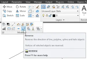
Probably my favourite entity in AutoCAD is the polyline. However, there have been a few things in the past that I’ve found somewhat annoying, one of which is controlling the direction of polylines.
Normally the direction of polylines makes little difference, but for some purposes it can be important. For example, linetype text is oriented in line with the direction of the line segment, so if the polyline flows from right to left, as opposed to from left to right, the text will appear upside-down.
Reversing the vertices in a polyline has historically been quite cumbersome to achieve, but as of AutoCAD 2010, there is now a REVERSE command. Simply enter the REVERSE command by either typing it, or selecting it from the Home ribbon, and select the polyline you want to reverse.
This command can also be used on a few other entities, namely LINE, SPLINE and HELIX entities.
Have you ever done a ZOOM Extents and found objects way out there like stars in outer space? Or tried to delete a layer but found you couldn’t because there was an object on it — but you couldn’t find it?
When troubleshooting objects, you might find it useful to have a list of them all. You can get that with DBLIST. Just type the command on the command line and press Enter whenever it pauses. Of course, in a busy drawing, that could take a while. And the list gets long even in a small drawing, because AutoCAD tells you everything about each object, like the LIST command does for selected objects. Below is the list for a drawing with only 5 objects!
Perhaps a better way to use it is to erase everything you can find and then run DBLIST. That way, you can see what is still left. You can then undo the ERASE command. (Luckily, undoing the DBLIST command, which came after, won’t delete your list!)
How do you troubleshoot wayward objects?
Command: dblist
CIRCLE Layer: “0” Space: Model space Handle = 1c4 center point, X= 8.8432 Y= 9.7202 Z= 0.0000 radius 5.2470 circumference 32.9678 area 86.4907
LWPOLYLINE Layer: “Layer1” Space: Model space Handle = 1c8 Closed Constant width 0.0000 area 20.3371 perimeter 18.2710
at point X= 21.1067 Y= 10.7852 Z= 0.0000 at point X= 26.4006 Y= 10.7852 Z= 0.0000 at point X= 26.4006 Y= 6.9436 Z= 0.0000 at point X= 21.1067 Y= 6.9436 Z= 0.0000
Press ENTER to continue: CIRCLE Layer: “Layer1” Space: Model space Handle = 1c9 center point, X= 15.0511 Y= 14.9691 Z= 0.0000 radius 2.2651 circumference 14.2322 area 16.1188
LINE Layer: “0” Space: Model space Handle = 1ca from point, X= 17.5267 Y= 7.1338 Z= 0.0000 to point, X= 30.2472 Y= 12.8391 Z= 0.0000 Length = 13.9414, Angle in XY Plane = 24 Delta X = 12.7205, Delta Y = 5.7054, Delta Z = 0.0000
LINE Layer: “0” Space: Model space Handle = 1cb from point, X= 30.2472 Y= 12.8391 Z= 0.0000 to point, X= 33.5226 Y= 7.9706 Z= 0.0000 Length = 5.8678, Angle in XY Plane = 304 Press ENTER to continue: Delta X = 3.2753, Delta Y = -4.8686, Delta Z = 0.0000
Sometimes you need to hide your dirty laundry. The WIPEOUT command lets you do just that. You can create a polygonal outline that is filled with the drawing area’s background color. Everything behind the wipeout is covered up.
Also check out our other blog discussing CLIP and WIPEOUT function in detail.
You might cover up part of your drawing that represents unapproved designs, confidential data, or anything else.
You can find the command on the Home tab in the expanded Draw panel. It’s also on the Annotate tab in the Markup panel. Here are the prompts:
Specify first point or [Frames/Polyline] <Polyline>: Specify next point: Specify next point or [Undo]: Specify next point or [Close/Undo]:
If you specify a point, you are prompted for more points so that you can create a custom shape, as you see here.
Here is the result when you press Enter to end the command.
If you have a polyline surrounding the area you want to cover up, you can choose the Polyline option. Then you see the following prompts:
Select a closed polyline: Erase polyline? [Yes/No] <No>:
Use the Erase polyline? prompt to specify whether or not to keep the original polyline.
At the first prompt, there’s a Frames option. The frame is the border that you see surrounding the wipeout. When you choose this option, you have 3 subuptions:
ON
OFF
Display but not plot
When you turn off frames, the wipeout seems to disappear, especially if no objects are partially covered by the wipeout, because it matches the drawing area background.
Just the very name DDEDIT brings back old memories! Once upon a time, DD was used to indicate that the command opened a dialog box. Now, it seems that there are only 3 left — DDEDIT, DDVPOINT, and DDPTYPE — listed in the alphabetical list of command in AutoCAD’s Help.
But there is no long a dialog box for DDEDIT. (The other two commands do open a dialog box.)
Editing single-line text
When you create single-line text (DTEXT) and double-click it, you can edit it in place, meaning you can simply type your correction. Nevertheless, AutoCAD starts the DDEDIT command. When you press Enter, you see the Select an annotation object or [Undo]: prompt. DDEDIT continues to prompt you to select another annotation object to edit (it doesn’t have to be DTEXT), making it easy to edit a number of text objects at once.
If you want, you can start the DDTEXT command first, but why do that? In fact, I couldn’t find the command on the ribbon at all! You can select the text, right-click in the Drawing area and choose edit, but that’s very roundabout.
Editing multi-line text (Mtext)
On the other hand, when you double-click Mtext (multi-line text), AutoCAD starts the MTEDIT command. As with the DDEDIT command, you do your editing in place. When you’re done, click outside the editor to end the command. There’s no prompt to edit another text object. So, the question arises, can you use DDEDIT on Mtext if you want to edit several Mtext objects in a row?
The answer is yes. Type DDEDIT on the command line. At the prompt, select your first Mtext object and edit it. Click outside the editor to end editing. DDEDIT repeats the prompt so that you can select another object.
DDEDIT is especially good when you want to edit both DTEXT and Mtext objects in one pass.
An excellent (and old) feature of AutoCAD is that you can define your own coordinate system:
The location of 0,0
The direction of the X axis
The direction of the Y axis
A custom UCS is a common aid for 3D drawing. For example, if you’re drawing a peaked roof of a house, it’s much easier to draw when you align the X and Y axes with the angle of the roof and set 0,0 to one corner of the roof. However, you can also create a custom UCS in a 2D drawing to rotate the axes and make drawing at an angle easier.
Starting in AutoCAD 2012, you can move and rotate the UCS by dragging it:
To move the origin, select the UCS, click the origin (the square handle), and click at the new location
To rotate the X and Y axes, select the UCS, click one of the axis handles (circular handles) and click at the new location.
Otherwise, you use the UCS command. You can find it in the 3D Modeling workspace on the View tab, in the Coordinates panel. The UCS command has lots of options and there are buttons for all of them:
World: The default UCS, with a horizontal X axis, vertical Y axis and origin at the default 0,0 point
Origin: Sets a new 0,0 point without changing the direction of the axes
View: Aligns the axes with the current view and arbitrarily sets the origin
X: Rotates the Y and Z axes around the current X axis.
Y: Rotates the X and Z axes around the current Y axis.
Z: Rotates the X and Y axes around the current Z axis. This is used in 2D drawings.
Object: Aligns the UCS with an object.
Z-Axis Vector: Specifies which way the Z axis points.
Face: Aligns the UCS with the face of a 3D solid
3-Point: Lets you specify the origin, then the positive direction of the X axis and finally the positive direction of the Y axis. I used this option to set the UCS shown in the above figure of the roof.
If you start the UCS command, you see the following prompt:
Specify origin of UCS or [Face/NAmed/OBject/Previous/View/World/X/Y/Z/ZAxis] <World>:
If you choose the NAmed option, you see the following prompt:
Enter an option [Restore/Save/Delete/?]:
You can use these options to save, restore, delete and list custom UCSs.
I recommend liberally saving custom UCSs. If you use it once, you’ll probably need to use it again!
Do you have any tips on creating and using UCSs? Leave a comment!
In an architectural drawing, you often need to break walls to insert a door. There are many ways to do this, but here is one way:
Let’s assume that you have a simple wall 4 inches thick. You want to insert a door that is 28 inches wide. You can easily translate these numbers into metric if you need to–the exact numbers don’t matter.
Use the BREAK command
At the Select object: prompt, select the bottom line of the wall — the one you’ll attach the door block to.
At the Specify second break point or [First point]: prompt, choose the First point option.
At the Specify first break point: prompt, use an object snap to specify the point on the wall line. You’ll need to find some way to make this point exact. At the very least, use the NEA object snap to make sure that you’re exactly on the line. If you use the NEA object snap, at the to prompt, click the line. Otherwise, specify the point using the object snap.
At the Specify second break point: prompt, specify the distance using relative coordinates. In this instance, you would type @-28,0 and press Enter
Draw lines to the other side of the wall
Draw a line from one of the endpoints of the break to the other line representing the opposite site of the wall. You can use an Intersection or Perpendicular object snap.
Do the same from the other endpoint.
Break the other line
Start the BREAK command again. This time, it’s easy. Select the endpoint of the first short line you drew as the first point of the break and the endpoint of the second short line you drew as the second point of the break.
Move the door block into place
Ideally, your door block’s insertion point should be the point where the door meets the end of the wall. Here are the steps:
Select the door block.
Click the insertion point to make it “hot.”
Press the Spacebar to display the Specify move point: prompt.
Move the cursor to the endpoint of the wall and the short line you draw and click.
Deselect the door. The door is now in place between the break in the wall.
Points have many uses in AutoCAD drawings. They are used for construction purposes, to help you find a coordinate. You can find a point using the NODE object snap. Sometimes, they are used as symbols, especially the more visible point styles.
The default point style is a simple dot, but it’s hard to see. Some disciplines specify a certain type of point style, such as an x, a cross, or a circle. AutoCAD comes with 20 point styles, so you can generally find the one you need. You would usually define the point style first, and then use the POINT command, but if you change the point style, AutoCAD changes the style of existing points accordingly.
To specify a point style, follow these steps:
Choose Home tab> Utilities panel drop-down, Point Style in the Drafting & Annotation workspace. (This is the DDPTYPE command or PDMODE system variable.)
Choose the style you want. Note that the second style is invisible.
By default, the point size is relative to the screen. This means that the point size doesn’t change when you zoom in or out. This type of point is meant for reference. However, if you want to use the point to represent a real-world object, choose the Set Size in Absolute Units option and enter a size in the Point Size text box.
When you’re done, click OK.
Then use the POINT command to insert the points into the drawing. You can find this command on the ribbon, on the Home tab, in the expanded Draw panel. The tooltip says Multiple Points. When you specify a location for a point, AutoCAD continues to prompt you to Specify a point until you press the Esc key on your keyboard.
If you don’t want your points to appear when you plot, you can change the point style to the second point style, because it’s invisible. Another option is to put your points on a separate layer with the Not Plottable properly.
How do you use points?
Do you use them to represent physical objects or just for construction? Leave a comment!
Draw and edit faster and easier with these top 25 productivity tips every AutoCAD user should know. Check out “Top Productivity Tips Every AutoCAD User Should Know” at http://www.ellenhelps.me/25-Productivity-Tips
Custom commands can really make your work go more quickly. Even if they save only a fraction of a second, they make you feel like you’re saving time — that extra smoothness is very satisfying!
Here’s one that I like. It creates a 1-segment line. Yes, I could press Enter to end the LINE command, but since I often create just one line segment, it’s nice not to have to do that extra step.
Here’s the 1LINE command that I created. Yup, it’s pretty simple!
^C^C_line \\;
(The underscore before “line” allows for translation and isn’t necessary most of the time.)
The backslashes pause for you to specify the start and end points of the line. The semi-colon ends the command. I have an old tip on ways to end the LINE command quickly here.
Whether you receive drawings from others or just need to fix up some sloppy work created in-house, you sometimes need to change layer names and properties for objects in your drawings so that they match your layer standards.
A great way to do this is to use the LAYTRANS command, that is, the layer translator. You specify sets of Translate From and Translate To layers based on existing drawings. For example, if you have a drawing with Layer1 (bad form!), you can translate it to the OBJECT layer. This process is called layer mapping.
Set up layer mapping
If the layer names in your current drawing are meaningless to you, I recommend that you start by writing down how you want to map these layers. That’s because the dialog box you’ll be working in doesn’t give you any information except for the names. You can’t tell which color a layer is, for example.
From the drawing that you want to change, choose Manage tab> CAD Standards panel> Layer Translator (the LAYTRANS command). The Layer Translator dialog box opens.
In the Translate From box, you see the layers in your current drawing.
In the Translate To box, you can create new layers by clicking the New box, but usually you’ll click Load, navigate to another drawing that has the layers you need and use those. Then, you’ll see the layers you need in the Translate To box.
To map a layer, click it in the Translate From box. Then click the layer your want to map it to in the Translate To box. Finally, click the Map button. You can select multiple layers in the left-hand box to map them all to one layer in the right-hand box. When you’re done, you’ll see the layer mappings in the bottom box.
You can make changes by clicking the Edit or Remove button. You can save your layer mapping to a Drawing Standards File (.dws) or a drawing file. In fact, if you don’t save it, AutoCAD will prompt you to do so.
Finally, click Translate.
Do you use this Layer Translation feature? Leave a comment!
Important: While we don't collect cookies, some of our 3rd-party services (such as PayPal and WordPress) do, to give you a safer and better browsing experience. Read about how we use cookies and keep your personal information secure by reading our Privacy Policy here.