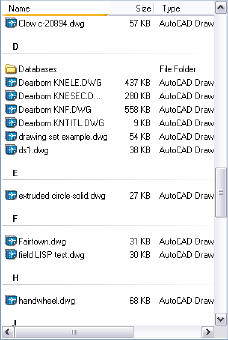
Some of you may remember the Today feature of AutoCAD 2002, which was a front-end window that allowed you to open existing files, create new files, and so on. One of its views was an alphabetical list of files, separated by the first letter of their name. Another was a listing by date.
Today quickly disappeared (and became yesterday), but some people missed this listing as a way to quickly find files. Kent Elrod, of Sumco Phoenix Corp. sent in this tip that explains how to organize files similarly in Windows XP.
When you’re ready to open a drawing, you choose File > Open to get the Select Drawing dialog box. Place the cursor over some white space in the area where the files are listed, right-click, and choose Arrange Icons By > Show in Groups. If the files weren’t already sorted by name, click the Name header. (If you don’t have any headers, click Views at the upper-right corner of the dialog box and choose Details.)
To see the files by date, click the Date Modified heading.
Kent notes that you can do this in Windows Explorer as well, and click on any header to sort by that header.
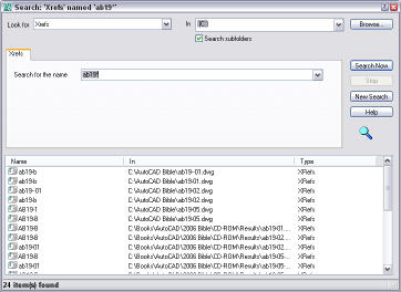
Would you like to know in which drawings a specific file is used as an xref? Let’s say that you’re editing a drawing and you’re pretty sure that it’s used as an xref in some other drawings. Changing the drawing will change these other drawings, too.
Mai Ezzat of Egypt sent in this tip to solve this problem.
Open the DesignCenter and click the Search button.
From the Look For drop-down list, choose Xrefs.
From the In drop-down list, choose a location.
In the Search for the Name text box, enter the name of the xref. You can use wildcards; for example ab19*. If you’re really ambitious, you can just put * to search for all the xrefs on your computer or network.
Click Search Now.
The results shows all the drawings that contain that drawing (or those drawings) as xrefs, as you can see here.
Mai Ezzat notes that you can click any column name to sort by that column, so you can easily sort by either the xref files or by the host drawings.
The eTransmit feature helps you send drawings to others by collecting all of a drawing’s associated files. It’s also an excellent tool when you simply want to move drawings. You can create a folder (use this option for moving files), a ZIP file, or an EXE file that is a self-extracting compressed format. You can automate the process of sending an e-mail with the transmittal attached.
Follow these steps:
Save your drawing. If there are any unsaved changes, you’ll see a message telling you that you need to save your drawing first.
Choose File> eTransmit. The Create Transmittal dialog box opens.
If you want, enter a note to the recipient in the text box at the lower-left corner of the dialog box. If you send an e-mail, the note will become part of the body of the e-mail. If you create an EXE or ZIP file, the note becomes part of the transmittal report, which is a separate file included with the drawing and other files.
Use the Select a Transmittal Setup box to choose a saved transmittal, if you’ve saved one from previous etransmittals. Otherwise, click Transmittal Settings to open the Transmittal Setups dialog box. Click New, name the transmittal and click Continue to create a new transmittal. If you have a saved transmittal that you want to change, choose it, and click Modify. Either way, you end up in the Modify Transmittal Setup dialog box.
From the Transmittal Package Type drop-down list, choose Folder, Self-extracting Executable, or Zip.
From the File Format drop-down list, you can choose an earlier release of AutoCAD. Use this feature if your recipient has an earlier release.
In AutoCAD 2008, there’s a checkbox, Maintain Visual Fidelity for Annotative Objects. This is checked by default, which saves each scale representation as a separate block on its own layer. Recipients with earlier versions can then choose which representation they want by turning off the unwanted layers or deleting the unwanted blocks.
From the Transmittal File Folder drop-down list, enter a location or click Browse to navigate to a location for the transmittal file. If you leave this blank, the files are saved in the same folder as the current drawing. (If you’re transmitting a sheet set, the file goes in the same folder as the DST file.
In the Transmittal File Name drop-down list, you can choose to be prompted for a file name, let AutoCAD assign a name (overwriting any existing file with that name), or let AutoCAD assign an incremental file name.
In the Transmittal Options section, choose one of these options:
Use Organized Folder Structure to create a hierarchical folder structure based on the structure of the files
Place All Files in One Folder to do just that
Keep Files and Folders As Is recreates the exact paths of the existing files
Check the Include Fonts check box to include AutoCAD fonts used. Choose this if you have created your own AutoCAD fonts that the recipient might not have. This option does not include TrueType fonts.
Check the Include Textures from Materials check box to include texture files.
In AutoCAD 2008, check the Include Files from Data Links check box to include Excel or CSV files that the drawing links to.
In AutoCAD 2008, check the Include Photometric Web Files check box to include web files that you have used for photometric data for lights.
Check the Send E-mail with Transmittal check box to open your e-mail program, create a new message, insert the note in the body of the message, and attach the transmittal file.
Check the Default Plotter to ‘None’ check box to do just that. If your recipient will plot the drawing and has a different plotter, this is a good idea.
Use the Bind External References check box to bind xrefs, rather than keeping them as separate files.
Use the Prompt for Password check box to let you specify a password after you save the transmittal file. You then give this password to the recipient, to make sure no one else can open the drawing.
If you want, add a description at the bottom that describes the choices you have made.
Click OK to return to the Transmittal Setups dialog box. Select the transmittal that you want and click Close. You’re now back in the Create Transmittal dialog box.
You can click the Files Table tab to check which files will be included in the transmittal file. Note that eTransmit does not include files that you hyperlinked to.
To add a file manually, click Add File, navigate to the file, select it, and click Open.
Click the View Report button to see the Transmittal Report, which includes your note and instructions to the recipient, depending on the choices you made. You can choose Save As to make a copy for yourself.
Click OK to create the transmittal. If you chose to send an e-mail, your e-mail program opens.
When you create a layout, including viewports, a title block, text, and so on, you can save it as a template to use in the future. If you would sometimes like to use a layout from a different drawing, one that isn’t included in your drawing’s template, and therefore not available to you in your drawing, then the LAYOUT command is ideal.
You can specially save a layout as a template, or you can use a layout from any existing drawing or template. What’s special about using templates in this way is that you get only the layout and its objects, layers, and settings; you don’t import any model space objects, block definitions, layers, and so on. So it’s a clean way to use existing layout in your current drawing and you don’t need to purge unwanted definitions.
Save a layout template
First, name the layout tab, because a name of Layout1 won’t be very helpful.
When you create a unique layout that you might want to use at another time, enter layout on the command line. At the prompt, use the SAveas option, and enter the name of the layout.
Enter layout option [Copy/Delete/New/Template/Rename/SAveas/Set/?] <set>: sa Enter layout to save to template <3-detail>:
The Create Drawing File opens, with the Template folder automatically selected and the template file type specified. Enter a name for the template, perhaps the same as the name of the layout, and click Save.
Use a template layout
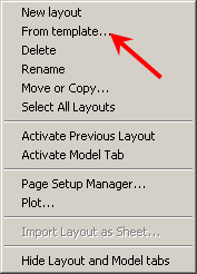
To use a template layout, right-click a layout tab, and choose From Template.
In the Select Template from File dialog box, choose the template that you want and click Open.
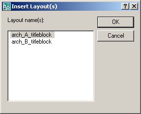
In the Insert Layout(s) dialog box that opens, choose the layout that you want, and click OK. AutoCAD creates a new tab with the same name, settings, and objects as the source layout.
Note: You can choose any drawing file, not only a template.
Note: If the viewport layers are frozen in the template or other drawing, they’ll come in to your drawing frozen.
A DWF file is a vector image format that you can use to share your designs with others, without sending the actual drawing. You might do this to share your designs without revealing the details, or to send them to people without AutoCAD. The recipients use Autodesk Design Review to view the DWF file. Autodesk Design Review is a free download, available from www.autodesk.com/designreview.
Follow these steps to create a DWF file:
Open the drawing or drawings that you want to use. You can include more than one drawing and layout in the DWF file.
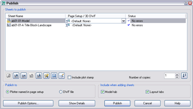
Choose File> Publish to open the Publish dialog box.
Use the Add Sheet and Remove Sheets buttons to add or remove drawings and layouts. Other buttons lets you change the order, choose a Page Setup, change the page name, and save the list of drawings for future use.
From the Publish To section, choose the DWF File option.
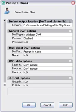
Click the Publish Options button to open the Publish Options dialog box.
In this dialog box, you can specify the location, a single- or multi-page file, file name, and password. You can also choose to provide layer, block, and sheet set information. For example, if you provide layer information, viewers can turn layers on or off. Click OK.
In the Publish dialog box, click the Publish button.
At the message asking if you want to save the list of sheets, answer Yes if you may want to create the DWF again for those drawings and layouts. Otherwise, click No.
You may see a message saying that the publishing is going on in the background. Click OK to create the file.
To view the file, you should be able to double-click it. Autodesk Design Review is installed with AutoCAD automatically. If not, you can find it in your Program Files\Autodesk folder.
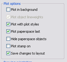
When you set up a plot in the Plot dialog box, you can save your settings to the Model tab or any layout tab. In the Plot dialog box, check the Save Changes to Layout check box. Then, the next time you plot from the same tab (Model or layout), the default settings will be the same and you can just plot.
You’ll find this check box in the Plot Options section of the Plot dialog box. If you don’t see that section, click the right-facing arrow at the lower-right corner of the dialog box to expand it and display the Plot Options section.
While you create your drawing, you may specify named views (View > Named Views) that display areas you’ll want to show in a viewport on a layout (paper space).
When it comes to creating viewports, you can display a named view in a couple of ways. One, of course, is to double-click inside a viewport and choose View > Named Views. There you can choose the named view you want and make it current.
But you can also display a named view while you create the viewport, saving some steps. Here’s how:
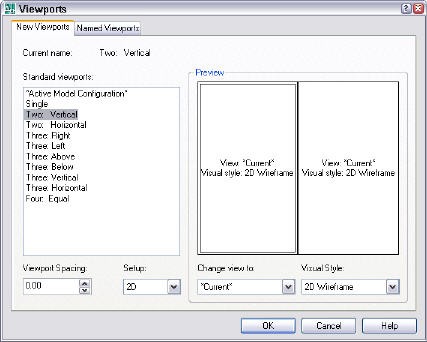
Choose View > Viewports > New Viewports to open the Viewports dialog box.
Choose the configuration you want. Then, for each viewport that you see in the preview, click it to make it active, and choose the named view from the Change View To drop-down list.
You can even choose a visual style for that viewport from the Visual Style drop-down list.
Do you ever print out draft plots on a black & white laser printer? If so, you may have found that the plots were in grayscale and some of your objects were such a light gray that they were hard to see. Instead, you’d probably like all objects to appear in full black.
Here’s a simple technique to accomplish this task:
Start the PLOT command.
Click the More Options button at the lower-right corner of the dialog box to open the right side, shown here.
Click the drop-down list in the Plot Style Table section at the top and choose monochrome.ctb (or monochrome.stb). This is a plot style that prints everything in black, just what you want.
Make sure that the Plot with Plot Styles check box (a little further down) is checked.
Now, plot again and all your objects will be dark black.
“I draw diagrams in AutoCAD and export them as Windows Metafiles(WMF). After that I import them to an MS Word document. Unfortunately they are imported with the background. But I want them without background (only the line work). How do I overcome this problem?”
This is a common task. WMF is a vector format, so it’s ideal for creating images from AutoCAD objects. Here are the steps to create a WMF file:
Choose File (AutoCAD button)>Export> Other Formats.
In the Export Data dialog box, from the File of Type drop-down list, choose etafile (*.wmf).
Specify a file name and location, then click Save.
At the prompt, select the objects that you want to export and press Enter to end selection.
Now you can insert that image file into another program, such as Microsoft Word or PowerPoint. Note that sometimes the image seems to be rotated, but you can rotate it as desired in the destination program.
By default, you should not get the background. The system variable WMFBKGND controls the background. Set it to Off to make the background transparent. This is the default value, so if you get the background, either it was changed or perhaps the version of AutoCAD is pre-release 2000. I took a screen capture of this cylinder after importing it into Microsoft Word.
Another system variable, WMFFOREGND, works only when WMFBKGND is Off and controls the line color. By default its value is 0, which swaps the foreground and background colors to make the objects darker than the background. If you use a black screen and your object is white, you don’t want the object to export as white, but as black. So AutoCAD would convert the black to white and vice versa.
Even if you only select 1 object when creating the WMF, AutoCAD creates a large file area. You can get rid of this by cropping the image in the destination program. You can also ungroup the WMF file in Word and PowerPoint, letting you format the individual objects. When you do this, it becomes clear that you’re seeing a 2D representation of a 3D object.
Since AutoCAD 2004, you can create multi-page DWF files. These are great when you want to send one DWF file but many drawings or layouts to someone. The new DWF reader (now called Autodesk DWF Reader) can also display these multi-page files. Suppose you have some existing DWF files and want to combine them into the new format? You can use the free MergeFiles application, available unofficially (and without support) from Autodesk. Download it here. Here are the instructions to install and use this application:
Unzip the ZIP file, keeping the files in the same folder. Double click the MergeFiles.exe file to open the application. Click Add Files or just drag a bunch of DWF’s from Windows Explorer onto the application. Click Merge.
MergeFiles is compiled from the free DWF v6.0 Toolkit, which is for developers creating applications that read or write DWF files. For a method of combining DWF files that includes support, buy DWF Composer for $99. There’s a 30-day free trial.
Important: While we don't collect cookies, some of our 3rd-party services (such as PayPal and WordPress) do, to give you a safer and better browsing experience. Read about how we use cookies and keep your personal information secure by reading our Privacy Policy here.