Many people like to use the keyboard to enter commands, but some of the commands are long, hard to type, or difficult to remember. You can create keyboard shortcuts for commands, such as DL for DIMLINEAR or RVC for REVCLOUD.
AutoCAD comes with a large number of aliases already made for you. You edit the acad.pgp file to add to these, or change them.
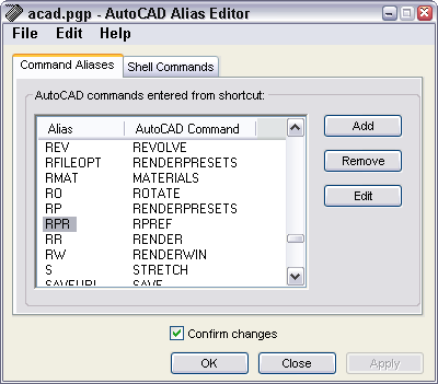
The acad.pgp file is a text file and you can edit it directly, but the easiest way is to use the Express Tools ALIASEDIT command.
Follow these steps:
Choose Express > Tools > Command Alias Editor.
After deciding the command and alias you want, check to see if the command already has an alias. Click the AutoCAD Command column to alphabetize the list by commands. Scroll to look for the command.
If it doesn’t have an alias, check to see if the alias is already in use. To do so, click the Alias column to alphabetize that column. Click any alias, and type the first letter of the alias to jump to aliases starting with that letter. Look for the alias.
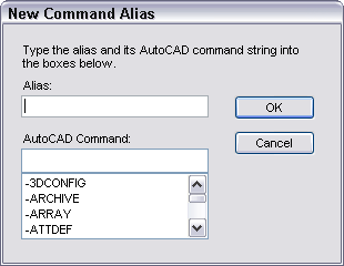
If your command isn’t listed and your alias isn’t being used, click Add.
Type the alias in the Alias text box and the AutoCAD command below it. All the commands are on the list, and as you start to type, the command appears on the list. You can click it as soon as you see it, or type the entire command. For example, I added rvc for REVCLOUD. Click OK.
If your command is on the list, but your alias isn’t, you can add the alias for the command. As before, click Add, enter the alias, and specify the command. A command can have more than one alias. I added dl for DIMLINEAR, even though there were other aliases for that command.
If your alias is being used, you can delete or change it. Then you can use it for a different command. For example, rc is the alias for RENDERCROP, which you might rarely use. By deleting it, you could use rc for RECTANG. To delete an alias, select it and click Remove, then click Yes to confirm.
You can change an existing alias. For example, you might want to change the alias for RENDERCROP to rencr, instead of deleting it. To do so, choose the alias, and click Edit. In the Edit Command Alias dialog box (which looks just like the New Command Alias dialog box), enter the new alias and click OK.
Note: You might be surprised to see some aliases on the list that are longer than their commands! Or completely different. AutoCAD uses this to map one command to another or to include command names that don’t exist, but that people might still use. For example, the RECTANG command has an alias of rectangle.
Top Customization Tips Every AutoCAD User Should Know
AutoCAD is meant to be customized, but customization is one of the most complex features of AutoCAD. Gain the knowledge you need to be a master at customizing AutoCAD!
Tip: To print the alias list, choose File > Print from the AutoCAD Alias Editor’s menu.
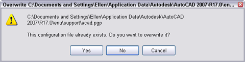
When you’re done, click OK. If the Confirm Changes dialog box is checked, you get a message asking you to confirm that you want to replace the configuration file (acad.pgp). Click Yes.
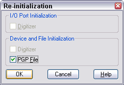
AutoCAD doesn’t recognize the change right away, because it doesn’t re-check the acad.pgp file during a session. You could close and re-open AutoCAD, but there’s an easier way. On the command line, enter reinit.
Check the PGP File check box and click OK. Now your new aliases will work. Try them out!
Note: You can edit the acad.pgp file directly. It’s in the Support folder. To find that folder, choose Tools > Options and click the Files tab. Double-click the Support File Search Path item and look at the first item. This file contains a User Defined Command Aliases section at the end where you can add your own aliases; these aliases override those in the main section. Use the same format as you see in the file, which is Shortcut,*Full_command_name. Save the file and use the REINIT command as just described.
You can attach other drawings to the current drawing to facilitate the drawing process. For example, you can attach a floor plan to a drawing of an electrical layout to make sure that you put the outlets in the right location. These other drawings are called external references, or xrefs.
Sometimes, xrefs can be large. For example, you may only want to see one room at a time in the floor plan. Or the xref may contain an entire city block and all you want is one house.
For this purpose, you can clip xrefs so that you see only the portion you need. It’s similar to cropping an image in an image-editing program, except that the process is temporary (you can undo it) and doesn’t affect the original drawing at all. Whatever is outside the clipping boundary disappears until you turn off the clipping boundary.
Although many people don’t realize this, you can also clip blocks that you insert into a drawing.
To clip an xref or block, use the XCLIP command. Choose Insert tab>Reference panel> Clip.
Select the xref or block and press Enter to end selection.
At the [ON/OFF/Clipdepth/Delete/generate Polyline/New boundary] <New>: prompt, press Enter to use the New option.
At the [Select polyline/Polygonal/Rectangular/Invert clip] <Rectangular>: prompt, you can do one of the following:
Press Enter to use the default Rectangular sub-option. Then specify two corners of the rectangle to clip the xref or block.
Specify the Polygonal sub-option and pick points to specify a multi-sided shape to clip the xref or block
Specify the Select Polyline sub-option. Then select an existing polyline to use as the clipping boundary.
Specify the Invert Clip sub-option to clip whatever is inside the boundary and then choose one of the three previous options to specify that boundary.
Here you see an xref with a polygonal clip.
Once you have a clipping boundary, you can use the command again and choose the OFF option to re-display the entire xref or block. However, AutoCAD remembers the boundary, so you can use the ON option later on to turn it back on.
The Clipdepth option is for 3D drawings only and specifies front and back planes for the clipping boundary.
The Generate Polyline option draws a polyline from an existing clipping boundary, using the current layer and linetype. You can then edit that polyline using the PEDIT command if you want to redefine the clipping boundary later.
The most obvious problem is that you can’t open a drawing. Here are some techniques to try:
Rename the drawing’s BAK (backup) file by changing its filename extension to .dwg and see if you can open that.
Find any temporary files (auto.sv$ by default) and rename them with a DWG extension and try to open them.
Open a new drawing and try to insert the drawing (use the INSERT command). If it works, EXPLODE the drawing after you insert it. Then use the AUDIT command.
Open a new drawing and try to insert the drawing as an external reference. (Choose Insert > External Reference.) Then use the AUDIT command.
If the drawing crashes just when it seems to be almost loaded, try again but this time press Esc repeatedly until the loading is complete. This procedure stops the regeneration of the drawing, which may be causing the crash. Then use the AUDIT command.
Finally, try the RECOVER command. Open a new drawing and choose File > Drawing Utilities > Recover. Choose the drawing from the dialog box and click OK. Actually, there’s no harm in using RECOVER first and then trying the other techniques.
If you can open a drawing but get an error message, use the AUDIT command, which you can find right next to the RECOVER command on the File menu. AutoCAD tries to correct any errors.
Check out this free dynamic block tutorial
Plus get free tips in our AutoCAD Tips Newsletter!
Get a free tutorial on creating a complete dynamic block, including a drawing to practice on. You'll make a movable chair, resizable desk, and more. PLUS, the highly-acclaimed AutoCAD Tips Newsletter will keep your skills up to date!
Timothy Keyser suggests setting the AUDITCTL system variable to 1 to create a log file of the results of the AUDIT command in your working folder with the same name as your drawing and a filename extension of .adt. He notes that this report is overwritten every time you use the AUDIT command, so it you want to save it, move it to another folder or rename the file. You can also send this file to Autodesk to help them troubleshoot your drawing.
If you can’t correct some settings, and it’s driving you crazy trying to find them, select everything in the drawing and choose Edit > Copy to copy everything to the Clipboard. Open a new drawing with a template you know and trust and choose Edit > Paste. You can also open a new drawing with the Start from Scratch option to open a drawing with as few settings as possible. Another technique is to use WBLOCK to save all the objects in the drawing as a new drawing file. This is similar to the previous technique.
I received a question about how to replace one block with another block. Replacing blocks is useful for 3 reasons:
To create multiple versions of a drawing, each with a different block. For example, you could try out a floor plan with different desks.
When your company replaces one part with another part
If your drawing is very complex, to reduce regeneration time, by replacing a complex block with a simpler one. Of course, before plotting, you would reverse the replacement.
There are two methods to replace one block with another.
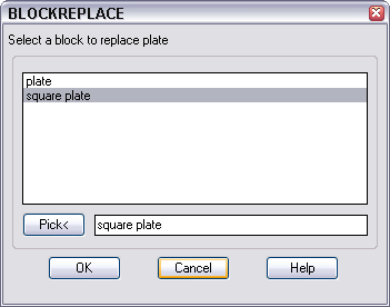
Use Express Tools BLOCKREPLACE
This Express Tool lets you replace one block with another globally in a drawing. Follow these steps:
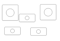
Make sure that the new block you want to insert is defined in the drawing. (If necessary, insert it to check.)
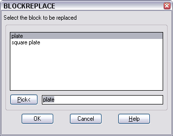
Choose Express> Blocks> Replace Block with Another Block or enter blockreplace on the command line.
In the BLOCKREPLACE dialog box, choose the block that you want to replace from the list of blocks in the drawing.
Click OK.
Still in the dialog box, choose the block that you want to use to replace the original block.
Click OK.
At the Purge unreferenced items when finished? <Y>: prompt, enter y or n.
You see a message, n blocks replaced. Results may not be apparent until next regen. If necessary, do a regen. (In my test, I didn’t need to regenerate the drawing to see the new block.)
Tips from our reader : If the BLOCKREPLACE command changes the scale of the block after replacement, find your block in the drop-down list and uncheck the box next to Annotative.
## Dynamic block is another great productivity tip to master. It creates rules and restrictions that control the appearance and behavior of a block when it is inserted into a drawing. Sign up below to get your Free tutorial on creating a complete dynamic block, including a drawing to practice on. You’ll make a movable chair, resizable desk, and more.
Use the -INSERT command
This older method allows you to replace a block in your drawing with a file. If necessary, first use the WBLOCK command to export the new block to a file. Follow these steps:
Type -insert on the command line.
At the Enter block name or [?] <square plate>: prompt, enter blockname=filename, where blockname is the name of the block in your drawing and filename is the name of the file containing the block you want to use. If the file is not in the support file search path, type the entire path. (You don’t need to add .dwg.) Press Enter. For example:
square plate=c:\drawings\plate
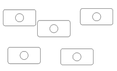
At the Block “square plate” already exists. Redefine it? [Yes/No] <N>: prompt, enter y and press Enter. You see the message: Block “square plate” redefined (with your block name inserted).
At the Specify insertion point or [Basepoint/Scale/X/Y/Z/Rotate]: prompt, press Esc to not insert a copy of the new file; all you want to do is redefine the old block.
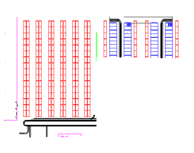
Here, I replaced the square plate block with the plate block, which was in plate.dwg.
Duplicate and overlapping objects waste ink and mean that your drawing isn’t accurate. However, often, they’re invisible.
The OVERKILL command, part of Express Tools, can help. This command deletes duplicate objects and goes further to combine overlapping lines and arcs. However, it’s not on the menu, toolbar, or ribbon, so you have to type it on the command line. For that reason, many people don’t know about it. (Update: As of AutoCAD 2012, this command is part of core AutoCAD. and is now on the ribbon. Go to the Home tab, Modify panel, and expand it to find the button.)
When you start the command, the next prompt is Select objects: and you can type all and press Enter to apply the command to the entire drawing. Then press Enter again to end object selection.
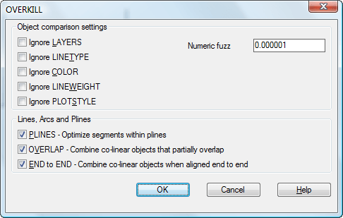
The Overkill dialog box opens.
To keep the default settings, just click OK. If there are duplicate or overlapping objects, you’ll see a message like this:
1 object(s) deleted.
You can specify lots of settings to control the process. For example, you can check the Ignore LAYERS check box to delete overlapping lines, even if they are on different layers.
Check out this free dynamic block tutorial
Plus get free tips in our AutoCAD Tips Newsletter!
Get a free tutorial on creating a complete dynamic block, including a drawing to practice on. You'll make a movable chair, resizable desk, and more. PLUS, the highly-acclaimed AutoCAD Tips Newsletter will keep your skills up to date!
The Numberic Fuzz text box determines how exact two objects must be to be considered duplicates. The default, 0.000001, deletes almost exact objects. You can change this to 0, to delete only objects that are exactly on top of each other.
The PLINES check box, on by default, removes duplicate line or arc segments within a polyline, or lines and arcs that overlap a polyline. If you uncheck this, the command only removes duplicates of entire polylines.
The OVERLAP check box, also on by default, combines objects that partially overlap into one object.
The END to END check box combines objects that don’t overlap, but are end to end, such as two colinear lines with one common endpoint.
Click OK to execute the command.
Draw and edit faster and easier with these top 25 productivity tips every AutoCAD user should know. Check out “Top Productivity Tips Every AutoCAD User Should Know” at http://www.ellenhelps.me/25-Productivity-Tips
One of the new features in AutoCAD 2008 is data extraction. This might make you think of block attributes and data connectivity, but it combines features of both. It’s both simple and powerful.
You start with the new DATAEXTRACTION command, or by starting the TABLE command and choosing the From Object Data in the Drawing (Data Extraction) option. Either way, the Data Extraction wizard opens.
Here are the basic steps:
Choose to start a new extraction or modify an existing one
Choose whether you want to include data from multiple drawings or just the current drawing. If you choose to extract data from multiple drawings, you can’t choose objects in those drawings. You can add drawings individually, or add an entire folder. If you choose to extract only from the current drawing, you can then go back to the drawing and select objects.
Then you choose which categories of data you want, and further refine the selection by choosing properties within those categories. You can extract 10 categories of data from objects, although not every drawing contains all 10 categories. These are:
3D Visualization, including materials
Attributes
Drawing data, such as file name, file size, and more
Dynamic Blocks, meaning their properties
General, which means properties such as color, layer, etc.
Geometry, which includes X,Y coordinates, and other object-specific data
Misc, which includes block unit and closed/open status
Pattern, which means hatch pattern properties
Table, which is table properties
Text, which includes single or multiline text properties
Next you refine the data. You can create formulas, specify data format, and more using the right-click shortcut menu. You can also sort columns and link to external data.
On the next page, you choose whether you want to create a table, an external file, or both. You can create XLS, CSV, MDB, or TXT files.
Finally, you place the table, specify the file name and location, or both. Here you see part of a table that includes drawing information from an entire folder of drawings.
The data extraction table is linked to its objects. If you change the data, you’re notified when you try to plot or publish a drawing. For example, if your table includes objects within a drawing and their X,Y coordinates, and you move one of those objects, you see the following dialog box when you start the PLOT command. You can then click Update to keep the table accurate before plotting.
Need to create a drawing at an angle? AutoCAD offers several options.
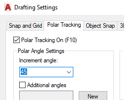
Use polar tracking to guide you
Right-click the POLAR button on the Status bar and choose Settings or click its down arrow and choose Tracking Settings. Set the angles you want and click OK. For example, a 45° angle will display tracking guides every 45°. Click OK. Now you can use polar tracking and direct distance entry (just type in the distance of a line) to draw.
Rotate the crosshairs
Thanks to Garry Stack of CADCO in Cork, Ireland for his tip suggesting this method. He likes it better because he finds that the tracking guides get in the way. To rotate the crosshairs, right-click the SNAP button on the Status bar and choose Settings. Type a value, such as 45° for the Angle and click OK. Now your crosshairs are at that angle. However, you need to use ORTHO to use direct distance entry using this method. Garry suggests making toolbar buttons for commonly used angles. For example, the macro to rotate the crosshairs 45° would be ‘snapang;45; I think it would be useful to have a ‘snapang;0; toolbar button as well. Lots of people seem to like this tip. Jack Foster writes that he has a button with the following macro: snapang;0;;\ This sets the snap angle to 0 regardless of what it currently is, then goes back to the snapangle variable and waits on the user to type in the new angle you want. Matt Doyle likes this version: ^C^Csnap;r;\\;off; This lets you set the angle by picking two points, then shuts off the snap command (which otherwise is turned on and snaps you to the grid). Ian Matthews contributed this pair: ‘snap r 0,0;per; ‘snap r ;0; The first one matches the cursor of a line you select. The second one returns the snap angle back to 0. He puts these on two toolbar buttons.
Jon Jonas prefers using the command prompt, so he defines two commands using AutoLISP:
He explains, “SNR sets the snap angle up using 2 points while SN0 (S-N-Zero) resets it back to zero… Simply place it in the acad.lsp file and you are good to go.”
Nick Louis says, to change your crosshair angle, just type in snapang at the command prompt, then hit Enter. Now simply type the angle you want. Or, type the code below in your acad.lsp file and reload the acad.lsp file. Then just type sa for Snap Angle.
(DEFUN C:sa ( ) (COMMAND “snapang”))
Create a User Coordinate System (UCS)
To rotate the axes by 45°, choose Tools>New UCS>Z and type 45. Press Enter. (Or, as Jimmy Wesley suggests, type ucs, z and type 45.) You can use Polar Tracking with this UCS if you wish. Typing relative coordinates will be simplified (for example, @3,0 instead of @3<45). Jimmy further suggests a quick way to return to the default axes: type ucs and press enter twice. Andrew Hudson suggests creating your UCS this way. Draw a line at the angle you need, such as 7.6 degrees. Choose Tools > New UCS > Object. At the prompt, pick the line nearest the end that you want to be your new 0,0 point. Alan Praysman has a custom toolbar button that works as a toggle to rotate the UCS and then restore the WCS. To rotate the UCS, click the button and pick the endpoints of a line to specify the angle. Here’s the code:
Alan Ball from Auckland, New Zealand submitted: “I find the easiest way is to use the UCS command and type in 3. The command then asks for the 0,0,0 point and the X and Y axes. The 3 option vanished from the options shown as available with the UCS command a few years back, but is still available to use and is very handy if you don’t know the angle…you are working with.
Attributes are labels that you apply to blocks. You can extract them to create a simple database that you can then view in Excel or place in your drawing as a table. You use the EATTEXT command.
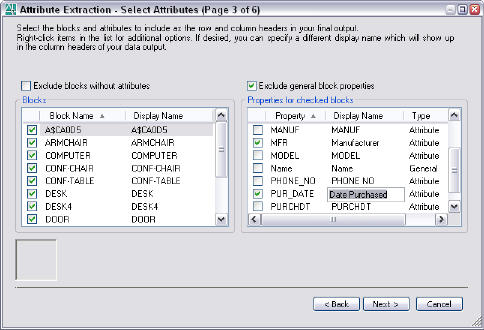
When you use EATTEXT, the Attribute Extraction wizard starts. Page 3 of the wizard looks like this:
On the left, you choose a block. On the right, you choose the data you want to extract for that block. However, the display names may not be easy to understand. In the right column, you can change the Display Name (called Alias in some earlier releases) to customize the headings in the resulting file and make them more readable.
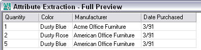
Here’s the result:
Now, for example, the last heading is “Date Purchased” instead of PUR_DATE. Much more people-friendly!
“First off, I’d like to say, love your blog and love your tips; So helpful! Especially the last one; coincidentally, I had been asking our CAD manager for the past three weeks if there was a way to give the “Break at Point” command (^C^C_break \_f \@ ) an alias, so that when we type “br” it does that instead of the regular “break” command.
“Your tip doesn’t exactly solve the issue, but it helps a little; I figured I might as well ask: Any idea how to achieve what I’ve been trying to do for weeks? (The CAD manager said he’d look into a solution through lsp programming, but hasn’t found anything so far)”
The tip Michael mentioned explains how to create a keyboard shortcut, but he wanted to type br. To do this, you need to create an AutoLISP command with that name. Michael’s question launched me into an effort to write an AutoLISP program. However, for some reason, I tried to write a program that would break an object at the original point specified, so that you could break an object with one point specification.
First of all, that’s not what Michael was asking for. His menu macro is equivalent to the Break at Point button on the Modify toolbar, which requires you to first select the object and then specify the break point.
Second, I already had an AutoLISP program that breaks an object with one point specification. It’s from Alan Praysman and available as a free download with my Breaking a Line into Two tip.
But lots of interesting code came out of the process, so I thought I’d share it with you.
I’m not a programmer, so anything I write is very amateurish. But here’s what I came up with (note that I used bap instead of br):
;;;breaks object at the point you use to select it (defun c:bap (/ object breakpoint) (terpri) (setq breakpoint (getpoint “Specify the break point “)) (setq object (ssget breakpoint)) (command “_break” object breakpoint “@”) (princ) )
I sent this back to Michael, noting that it doesn’t have any error trapping. Specifically, it just fails if you don’t select an object.
It defines a command, BAP, that asks for a break point. You can use an object snap. Then it breaks the object at that point.
Meanwhile, I sent this to Lee Ambrosius of Hyperpics.com. Lee is a real programmer and he sent this back. He notes that even this code is missing some error trapping for the situation where a user presses Esc before breaking the line.
(defun c:bap ( / object breakpoint) (terpri) ;; Set a single object (if (setq object (ssget “:S”)) (progn ;; Use the redraw function to highlight the selected object (redraw (ssname object 0) 3) ;; Get the second break point (if (setq breakpoint (getpoint “\nSpecify the break point “)) ;; Use the Break command to break the selected object at the selected point (command “._break” object breakpoint “@”) ;; Inform the user that no point was selected (progn (prompt “\nNo point selected.”) (redraw (ssname object 0) 4) ) ) ) ;; Inform the user that no object was selected (prompt “\nNo object selected”) ) (princ) )
This code does the same thing as mine, but adds some error trapping and a couple of other nice features.
Meanwhile, Michael replied:
“Thank you very much for your help Ellen. I used your LISP function to learn how LISP works, and then tweaked it to get it to do what I wanted. I’m not sure how well it works, as I’m not a programmer either, so I don’t know if it’s foolproof, but it does what I need it to so far. . “
“The main reason I had to tweak your version was because if two lines (or more) crossed each other, I could only use the command on the line that was on top in the drawing order, which wasn’t always the one I wanted.
“There was another problem too, which my LISP command can’t solve either. . . The problem is the following: The point I want too break a line at is where a 2nd line would intersect it if I were to extend it. To select this point, I drag an OTRACK line that extends from the 2nd line to the intersection. But when I click on the intersection, either the line stays intact, or the line breaks at a different point.
“When I perform the same actions using the “Break At Point” icon in the “Modify” toolbar, it does what I want it to. I’m not sure if it’s a LISP thing, or if it has to do with my AutoCAD settings, or with the program itself, or something else. If you have any ideas on that, I’d love it if you could send them over hear to help me solve this… otherwise I’ll have to settle for the tweaked LISP command…”
Here is Michael’s code:
;;;breaks selected object at the point you pick (defun c:bap (/ object breakpoint) (terpri) (setq object (entsel)) (setq breakpoint (getpoint “pick breakpoint “)) (command “break” object “f” breakpoint “@”) (princ) )
Now, you have four AutoLISP routines that can help you break objects quickly. You can see how even non-programmers can enjoy writing code and create something useful. Of course, you need to know something about AutoLISP, but amateurs can still create very useful programs. Give it a try!
Do you need to know which objects are on which layers? Count your layers? Hide objects on other layers? Layer Walk (the LAYWALK) command does all this and more. It was once part of Express Tools, but has become part of core AutoCAD.
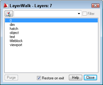
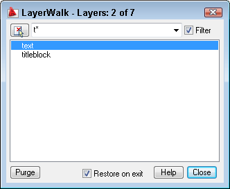
Layer Walk is quite a powerhouse and pulls together capabilities from several other commands into one dialog box. You can access it by choosing Format> Layers> Layer Walk. In AutoCAD 2009, go to Home tab> Layers panel (expanded)> Layer Walk. Of course, you can just type laywalk. The LayerWalk dialog box opens.
As you can see, you get an immediate list of all of your layers, plus a layer count.
In the text box/drop-down list at the top, you can enter a wildcard and press Enter to filter the layer list. If you have saved filters, you can choose one from the drop-down list.
By entering t*, I can display only layers starting with the letter “t.” I can easily display all of the layers again, by unchecking the Filter check box to the right.
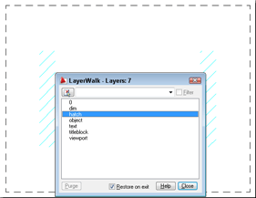
The best feature is that you can click any layer on the list to display only objects on that layer, hiding everything else. For example, I can easily click the 0 layer and make sure that nothing is on that layer, if my CAD standards say nothing should be on layer 0. Here you see the hatch layer selected, so only the hatches appear. You can select multiple layers using the usual techniques of Ctrl+click to select additional individual layers, or click, then Shift+click to select contiguous groups of layers.
With any layer or layers selected, you can right-click in the dialog box and choose Invert Selection to display the other layers and hide the selected layers.
If you select a layer that has no objects on it, you can click the Purge button to purge the layer.
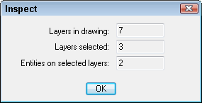
Right-click and choose Inspect to display the Inspect dialog box, which shows you the total layers in the drawing, the selected layers, and the objects on those layers.
By default, the Restore on Exit check box is checked, which returns you to your previous display when you close the dialog box. However, you can uncheck that check box to turn off undisplayed layers after you close.
All-in-all, a nice multi-purpose tool for managing your layers.
Important: While we don't collect cookies, some of our 3rd-party services (such as PayPal and WordPress) do, to give you a safer and better browsing experience. Read about how we use cookies and keep your personal information secure by reading our Privacy Policy here.


 Top Customization Tips Every AutoCAD User Should Know