Often, you need to zoom in to see a specific object. Since AutoCAD 2005, the ZOOM command has had an Object option that makes this easy, but many people still don’t know about it.
Just select the object and choose Zoom Object from the Zoom flyout. The view zooms in to display that object as if you’d placed a window perfectly around it. However, this method is often easier than specifying a window, if you’re interested in one object.
Starting with AutoCAD 2006, you can use the JOIN command to join objects that are colinear, meaning that they’re along the same line. Usually, you use JOIN to join lines or polylines. For example, you may have broken a line and now you need it whole again. The command fills in gaps, if necessary.
You can also use the JOIN command to join arcs that are along the same circumference or elliptical arcs that are along the same elliptical circumference. Just select an arc or elliptical arc and use the cLose option.
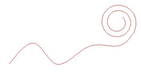
You can even join splines, as long as they don’t have any gaps. Help says that you can join helixes, but this didn’t work for me. Perhaps the language in Help is misleading, because I was able to join a helix with a spline.
Here is the result in a Top view:
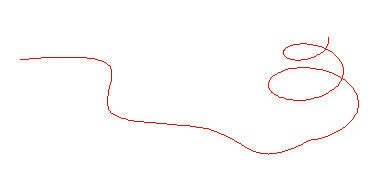
Even cooler, here it is in Souteast Isometric view:
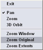
When you click either the Pan Realtime or Zoom Realtime button on the Standard toolbar, you can drag to pan or zoom. At this time, you’re in a special mode and you need to press Esc or Enter to return to the command line.
If you don’t like the result or just want to return to your original view, you could press Enter and then click the Zoom Previous button on the Standard toolbar, but this requires both hitting a key on the keyboard and then using your mouse to click the toolbar button.
I always find it awkward to have to use both the keyboard and then the mouse to accomplish something, so I was happy to discover that you can right-click in either Pan Realtime or Zoom Realtime mode and choose Zoom Original (even if you’re panning) from the shortcut menu.
Definitely faster!
In 3D Orbit, you can do the same. Right-click while in 3D Orbit mode and choose Reset View.
When you edit with grips, you can use the Copy option to copy as you edit. For example, if you are scaling a circle, use the Copy option to make concentric circles.
If you want to create a leader that points to more than one object, first create the leader pointing to one object. Then select the leader arrow. Click the grip at the arrow end to make it “hot.” Choose the Copy option at the Specify stretch point or [Base point/Copy/Undo/eXit]: prompt. Specify as many new end points as you want. Each new leader will be attached to the original Mtext at the end of the first leader.
Use the eXit option to end the command.
Note: In AutoCAD 2008, you can create leaders with multiple arrows using the MLEADER command.
You can adjust the dimension (the DIMSCALE system variable) or plot scale of a tool that you created by dragging a block, hatch, or xref from a drawing. To do so, right-click the tool and choose Properties. Click the Auxiliary Scale item. Then click the down arrow that appears at the right and choose either Dimscale or Plot Scale. Click OK. From now on, the item comes into your drawing at the scale you’ve set in your drawing.
But what if you’d like to change a different system variable, such as LTSCALE? Here’s how:
In AutoCAD, right click the tool and choose Properties. Choose DIMSCALE from the Auxiliary Scale drop-down list.
Choose Tools>Options and click the Files tab. Go to Tool Palettes File Locations to find the location of the Tool Palette ATC files.
Close AutoCAD and use Windows Explorer to navigate to the Tool Palette ATC files.
Use Notepad to open the ATC file named after your tool palette.
Find DIMSCALE assigned to your block and replace it with the system variable that you want to assign, such as LTSCALE. Save the file.
Open AutoCAD and check your Auxiliary scale value. It should now read the name of the system variable you chose, such as LTSCALE.
Thanks to Misha Belilovskiy of Autodesk for this tip.
Have you ever had the experience of redefining a block and finding that the insertion point is way off? Or perhaps the block just seemed to disappear and you couldn’t figure out where it went! It turns out that how you redefine the block makes a difference.
After you have exploded and changed the objects, choose Make Block. Instead of choosing the block name from the drop-down list, type it. You will never have the problem of the wayward insertion point again!
Note: Other possible reasons for this phenomenon are inadvertently snapping to the wrong object snap when you specify your insertion point and changing units.
Doug Merkley contributed an AutoLISP routines that “mends” lines. It joins two lines into one, using the start point of the first line selected and the end point of the second line selected to create the new line. Download it.
Mark McDonough contributed a different type of AutoLISP file, which he calls heal.lsp. It only creates the new line if the two selected lines are colinear, that is, at the same angle. Download it.
Are you used to dragging and dropping objects in graphics programs or even word processing programs? In AutoCAD 2000 you can drag and drop objects, either to move them or copy them. This is the easiest method when you don’t need exact precision about where your objects end up. There are two methods:
Select an object or several objects if you wish. With your left mouse button, click and hold down the mouse button anywhere on the object (or any one of the objects). You’ll see an arrow cursor. Drag (with the mouse button still held down) the object(s) wherever you want. Release the mouse button. To copy objects, hold down the Ctrl key as you drag. (You’ll see a little plus sign next to the cursor.)
Alexander Vulkov emailed me the following related tip from Bulgaria: Select an object or objects. Then, instead of using the left mouse button, right-click the object and drag. When you release the mouse button, a shortcut menu appears and you can choose Move Here, Copy Here, Paste as Block or Cancel.
Object snap settings let you quickly choose geometric points on an object. For example, you can set up a running (ongoing) Endpoint object snap (osnap, for short), so that whenever you get near the endpoint of an object, you can snap to it.
But sometimes, object snaps get in the way, especially if you want to specify a point near, but not on, an object snap. Temporary overrides are very helpful, because you can turn off the running osnap just for a second, while you finish your task.
Temporary overrides require you to press and hold a key, or key combination. As long as you hold down the keys, the override works. As soon as you release the keys, your running osnaps are back again. Note that some of the overrides turn on an object snap, some turn it off, and others toggle it.
I find the first one, which toggles object snap mode, most useful.
Here are the temporary overrides:
Toggle object snap mode: Shift+A or Shift+ ‘ (apostrophe)
Turn on object snap mode: Shift+S or Shift+; (semicolon)
Turn off object snap & object tracking: Shift+D or Shift+L
Note that each override has a left-handed and a right-handed option. If you use your right hand for the mouse (as I do, even though I’m left-handed), use the first option.
Print these out and attach them to the wall or a nearby bulletin board!
The Dashboard was introduced in AutoCAD 2007 for 2D tools and expanded in 2008 for 3D tools. Starting with 2008, it is also customizable.
The Dashboard has a little-known feature that lets you quickly display an associated tool palette. This tip works in both AutoCAD 2007 and 2008.
Each control panel (section) in the Dashboard has an icon at its upper-left corner. One feature of the icon is that it expands and collapses those control panels that are expandable. When you expand a control panel, you see additional tools. When you pass the cursor over the control panel, you also see a double-down arrow at the lower-left corner, which accomplishes the same task.
However, clicking the icon does something else; if the Tool Palette window is open, it displays a related tool palette (a tab of the window), if there is one.
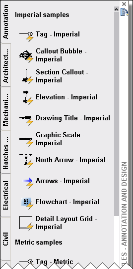
For example, if you click the Annotation Scaling icon , AutoCAD displays the Annotation tab of the Tool Palette window.
In cases where there is a tool palette group defined, you’ll get the last-used tab of that group. For example, there is a 3D Make group that has Modeling, Draw, and Modify tabs. When you click the 3D Make control panel, you see the last of those 3 tabs that you displayed.
Remember that the Tool Palette window must be open for this technique to work.
Here’s a list of the control panels and which tool palette or group they open:
2D Workspace
Layers
None
2D Draw
None
Annotation Scaling
Annotation
Dimensions
None
Text
None
Multileaders
Leaders
Tables
Tables
2D Navigate
None
3D Workspace
Layers
None
3D Make
Last used tab of 3D Make group
Visual Styles
Visual Styles
Lights
Generic Lights
Materials
Last used tab of Materials group
Render
None
3D Navigate
Cameras
Thanks to Shekhar Khedekar and Alex Bicalho of Autodesk for some of the information in this tip.
Important: While we don't collect cookies, some of our 3rd-party services (such as PayPal and WordPress) do, to give you a safer and better browsing experience. Read about how we use cookies and keep your personal information secure by reading our Privacy Policy here.