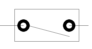
A donut looks like a wide circle with a hole in it but is actually made up of 2 semi-circle polylines. You can use donuts for electronic schematics, as trees or bushes, or as symbols.
Here are the steps to create a donut:
Choose Home tab and expand the Draw panel to find the DONUT command, or type donut.
At the Specify inside diameter of donut <2.0000>: prompt, type the diameter of the hole. To create a filled circle, type 0. The command remembers your previous diameter and uses it as the default.
At the Specify outside diameter of donut <4.0000>: prompt, type the diameter of the entire donut.
At the Specify center of donut or <exit>: prompt, place the donut by specifying where you want its center to go.
The command repeats automatically, so the next prompt is Specify center of donut or <exit>: Continue to specify center points or press Enter to end the command.
Fun fact: You can type doughnut to start this commend.
What do you use donuts for? Or, did you use donuts in the past and replace them with something else? leave a comment to share your experience!
Layers are a big issue when it comes to maintaining drawing standards. Where you work, you may have lots of rules about which layers your drawings can have.
Xrefs can be a problem for drawing standards, because when you attach an xref, its layers come along for the ride. This is especially an issue when the xrefs come from an outside organization, such as a subcontractor.
You can have AutoCAD notify you when new layers are added to a drawing. This layer notification feature doesn’t work with a drawing standards file but is just based on the layers that exist in your drawing. For more information about drawing standards files, see my post, “Use a Standards file to bring an AutoCAD drawing into line.”
Set up layer notification
Here are the steps to set up layer notification:
Choose View tab, Palettes panel, Layer Properties (or type layer) to open the Layer Properties Manager.
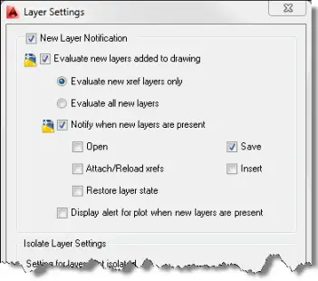
Click the Settings button (it looks like a wrench) to open the Layer Settings dialog box. You’ll use the top half of this dialog box.
Check the New Layer Notification checkbox.
Check the Evaluate New Layers Added to Drawing check box.
Keep the default option, which is to evaluate only new xref layers, or choose Evaluate All New Layers if you want to be notified whenever a new layer is added. If your templates already have all the layers you need, this option can help prevent inexperienced users from adding layers. At least, they’ll see a notification!
To specify when the notification appears, check the Notify When New Layers Are Present checkbox.
Use the other checkboxes it determine when the notification appears.
Click OK.
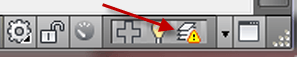
Note: If you don’t check the Notify When New Layers Are Present checkbox, you won’t see a notification bubble, but can still check for unwanted layers by right-clicking the Unreconciled New Layers alert icon on the right side of the status bar and choosing View Unreconciled New Layers. The Layer Properties Manager opens with a filter that displays only those layers. You can then delete them or change their properties.
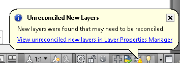
What to do when you get a notification
When you see a notification bubble or dialog box, click its link to open the Layer Properties Manager (with a filter that displays only unreconciled layers) where you can fix the problem.
When you start customizing the ribbon, you may want to create a new tab to hold all of your custom commands. On the other hand, you may want to add custom commands to existing tabs and put them in context.
If you want a new tab, here are the steps:
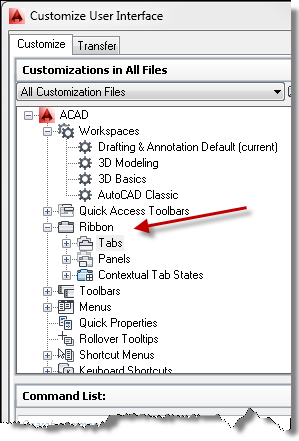
Type cui to open the Customize User Interface dialog box.
Expand the Ribbon item. Right-click the Tabs item and choose New Tab. Type a name for the tab (keep it short).
Right-click the Panels item and choose New Panel. Type a name for the panel.
Drag the new panel to the new tab.
To add the tab to your workspace. select the Workspaces item and choose the workspace. Find your new tab under Ribbon, Tabs and drag it to the Ribbon Tabs item in the Workspace Contents box. You have to be careful to drag without clicking your custom tab (and releasing the mouse button). If you expand the Ribbon Tabs item, you now see that your custom tab is there. You can also click OK to close the dialog box and see that the tab appears on your ribbon.
In the Customization in All Files section, under Panels, expand your new panel. A panel comes with a preset structure that you can change. Find the command in the lower-left box of the dialog box, called the Command List. If you want to add custom commands, choose Custom Commands from the drop-down list in the Command List section. This will help you find your custom commands more easily.
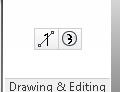
If your command doesn’t have a button, select it from the Command List and use the Button Image section at the upper-right to choose and edit your button. Click Save and save your image. It will be a BMP file. Remember the location!
To assign the image to the command, choose the command from the Command List section. Click the Small Image item in the Properties pane on the right. Click the Ellipsis button and browse to your BMP file. (Note: It’s possible to lose this type of customization when you upgrade to a new release of AutoCAD.)
To add the command to your panel, drag it from the Command List to Row 1 in your custom panel. This means that you’re dragging from the lower-left box to the upper-left box in the dialog box. There are lots and lots of panels, but yours should be at the bottom of the list.
Click Apply and OK. Click your new tab to find your custom commands.
But suppose you want to check standards for many drawings at once? You can, using the Batch Standards Checker. Here are the steps to use the Batch Standards Checker:
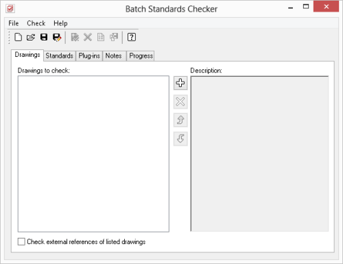
From the Windows task bar, choose Start>All Programs>Autodesk>AutoCAD 20xx – English>Batch Standards Checker. In Windows 8, move the cursor to the upper or lower-right corner to display the charms and choose the Search charm. With Apps selected, type Batch Standards Checker and select it when it appears at the left. The Batch Standards Checker window opens, as you see here.
On the Drawings tab, click the Plus (+) button and select the drawings that you want to include. Click Open. You can repeat this process to add drawings from a different location. To check xrefs attached to these drawings, check Check External References of Listed Drawings.
On the Standards tab, choose to check each drawing against its associated standards file if you have associated standards files for all of the listed drawings. Otherwise, choose to check the drawings against a standards file or files that you select. To select a standards file, click the + button, choose a standards file (.dws), and click Open.
On the Plug-ins tab, choose the standards that you want to check. You can check dimension styles, layers, linetypes, and text styles.
If you want, you can use the Notes tab to add notes that will appear in the report.
Click Save on the Batch Standards Checker toolbar. In the Batch Standards Checker – File Save Dialog box, save the standards check file (.chx), which contains information about the drawings and standards files you used for the batch standards check.
To start checking the drawings, click Start Check on the Batch Standards Checker toolbar or press Alt+T. The checking process start. You can click the Progress tab to see what is happening.
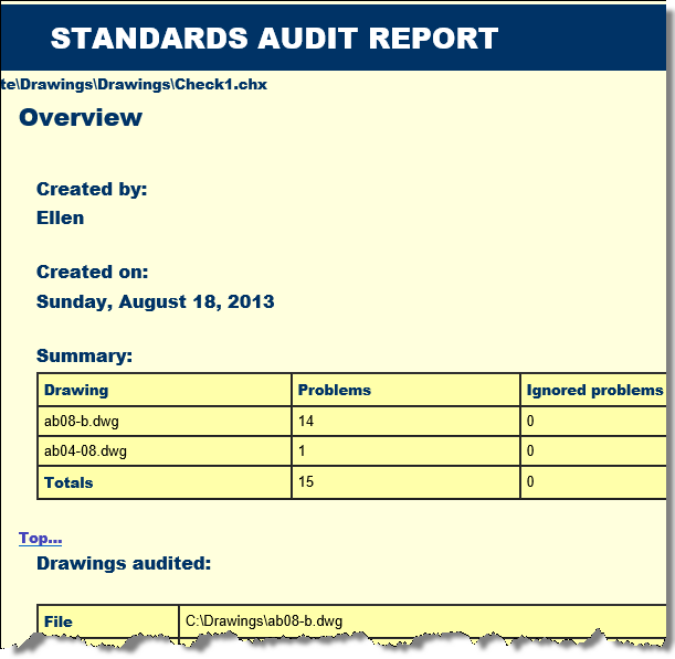
When the process is done, a Standards Audit Report is displayed in your browser. Mine opened in Internet Explorer, even though that isn’t my default browser.
Do you use the Batch Standards Checker? What is your experience with it? Do you have any tips for using it?
Recently, a reader asked how to plot a drawing in black & white except for text. I had a few thoughts — plot styles and layer states, for example — but one idea was layer overrides.
Let’s say that you want to create some plot variations of your drawing. One way to do this is to change the properties of a layer in a viewport. In this way, you have one layout with a viewport showing layers with their given properties — color, linetype, etc. On another layout, you might change the layer properties for a very different result. You actually make these changes per viewport, but I’ll assume one viewport per layout in this tip.
For example, you could change a layer’s color from green to black on one of the layouts. This feature is called layer overrides.
Set a layer override
Here is how to set layer properties for a viewport:
Display a layout and double-click inside the desired viewport to enter model space.
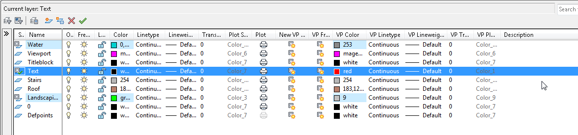
Open the Layer Properties Manager. You now see 5 special columns — VP Color, VP Linetype, VP Lineweight, VP Transparency, and VP Plot Style .
To override the properties of a layer for that viewport, click the layer’s item in the desired column, just as you normally do to change a layer’s property.
When the overridden viewport is current, the Layer Properties Manager displays a light blue rectangle for that override. The Layer drop-down list in the Layers panel on the Home tab also shows the light blue rectangle.
Remove a layer override
To remove an override, open the Layer Properties Manager and do one of the following:
To remove one property override for a layer — let’s say Color — right-click the Color column for the layer with the override and choose Remove Viewport Overrides For > Color > In Current Viewport Only or In All Viewports.
To remove all property overrides for a layer, right-click the layer and choose Remove Viewport Overrides For > Selected Layers > In Current Viewport Only or In All Viewports.
To remove all property overrides, right-click any layer and choose Remove Viewport Overrides For > All Layers > In Current Viewport Only or In All Viewports.
How do you create plot variations? Do you use layer overrides? Leave a comment and share your expertise!
A reader asked how he could display data that was linked to an Excel spreadsheet. It might be easier to update the data in the spreadsheet or you might be keeping the data there anyway for other purposes. For whatever the reason, it can be very efficient to create a data link and display the data in a drawing.
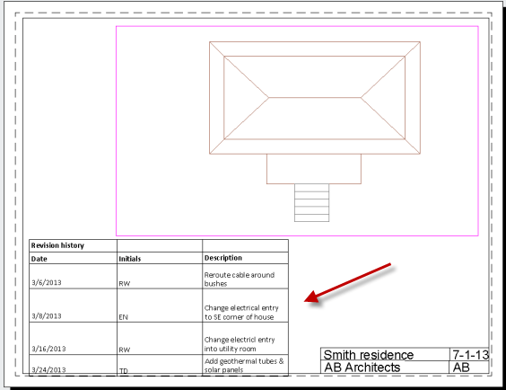
Here you see a table with a revision history.
You can do this in a table fairly easily. Here are the steps. Below is a video tutorial of the same procedure.
On the Home tab, in the Annotation panel, click Table.
In the Insert Table dialog box, choose the From a Data Link option in the Insert Options section.
Click the Launch the Data Link Manager Dialog button to the right.
Click Create a New Excel Data Link option.
Give the data link a name and click OK.
Wait a couple of seconds until the New Excel Data Link dialog box opens. At the top, click the Browse button to browse for a file. Navigate to the Excel file and click Open.
Back in the New Excel Data Link dialog box, choose which sheet you want to link to and also choose Link Entire Sheet, Link to a Named Range, or Link to Range. If you choose the latter, enter the range in the format A1::B12. As long as the Preview checkbox is checked, you’ll see a simple preview at the bottom.
Click OK 3 times to return to your drawing.
At the Specify insertion point: prompt, pick a point.
You can then select the table and make adjustments or format it.
Watch the video to see how these steps work. In the video, I also show you what happens when you change the data in Excel.
Draw and edit faster and easier with these top 25 productivity tips every AutoCAD user should know. Check out “Top Productivity Tips Every AutoCAD User Should Know” at http://www.ellenhelps.me/25-Productivity-Tips
A reader told me he was having problems with his 3DCLIP command after upgrading to AutoCAD 2013. He wrote:
“I create 3 or 4 different 3d models that I then xref them together into an arrangement drawing. I then create my viewports for the different views I will need. In the past, I would click into my viewport to get it into view model space and then I use 3dclip to adjust clipping planes to get the view looking the way I want it. I have found with Acad 2013 that I can’t do that anymore, when I get to 3dclip only my back clipping plane shows up, for some reason my front clip plane has disappeared – any idea why or how I might fix this?”
I told him I’d never heard ot this problem, so he wrote back.
“Hey Ellen, it’s the color of the clipping plane that is messing me up – with a black clipping plane and black background I can’t see it. If I change my background to white I can see the plane but my 50 yr old eyes can’t handle the white background. Any thoughts on how to change the color of a clipping plane?”
That rang a bell. Here’s what I told him to do:
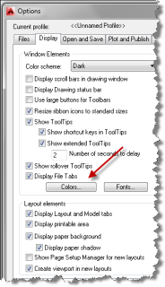
Start the OPTIONS command. You can right-click almost anywhere and choose Options.
The Options dialog box opens. Click the Display tab.
Click the Colors button to open the Drawing Window Colors dialog box. Here, you can alter the color of almost any interface item in the AutoCAD window — making AutoCAD the most customizable interface I know of. The most common item to change here is the drawing background, but you’ll find a lot more options here.
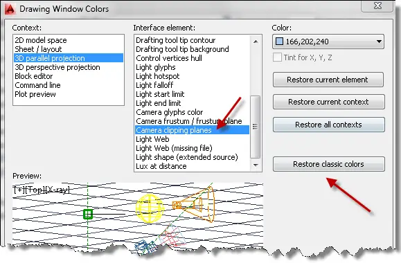
In this case, I said to choose 3D Parallel Projection (and repeat with 3D Perspective Projection) in the Context list. Don’t forget to choose the appropriate item in the Context box before going on.
Scroll down to the Camera Clipping Planes item. Or choose the item you want to change.
Click the Color drop-down list and choose a color. You can choose a standard color or click Select Color to specify any color you want.
Click Apply & Close.
Click OK to return to your drawing.
Here was his response:
“Hey Ellen, looks like you nailed it. I also chose Restore Classic Colors and that fixed it up nice as well.”
What interface item colors do you change? How does the new color help you? Leave a comment!
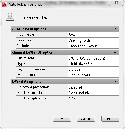
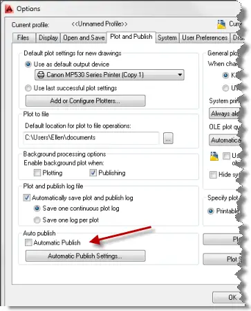
The AUTOPUBLISH command is a way to quickly publish to a DWF, DWFx, or PDF file. To specify the settings that this command uses, choose Application Button > Options and click the Plot and Publish tab. In the Auto Publish section, click the Automatic Publish Settings button. There you can specify settings similar to those you set by clicking the Publish Options button in the Publish dialog box. I cover the PUBLISH command here.
The AUTODWFPUBLISH system variable turns the AutoPublish feature on and off. When you turn this system variable on (set its value to 1), AutoCAD executes the AUTOPUBLISH command every time you save or close the a drawing. You can also turn this system variable on in the Auto Publish section of the Plot and Publish tab of the Options dialog box by checking the Automatic Publish check box. Turn on AUTODWFPUBLISH if you always need to keep DWF, DWFx, or PDF files synchronized with your drawings.
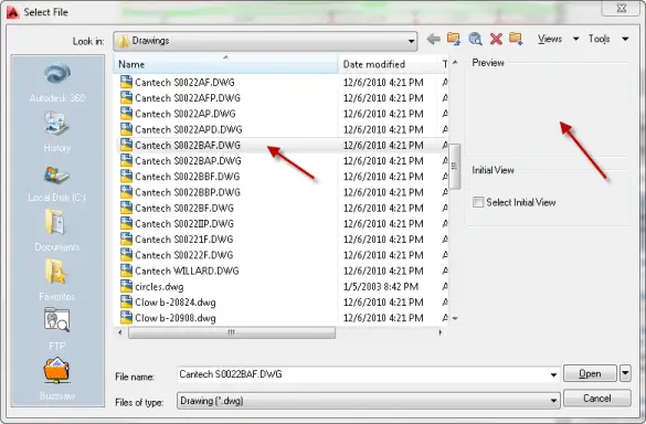
Do you have old drawings that don’t show thumbnails when you select them in the Select File dialog box?
Even though this drawing says it was last modified in 2010, it was created much earlier. It’s probably at least 15 years old.
The system variable that determines whether a drawing saves a thumbnail is THUMBSAVE. It replaces the earlier RASTERSAVE. The default value, 1, saves a thumbnail, but older drawings might not have one.
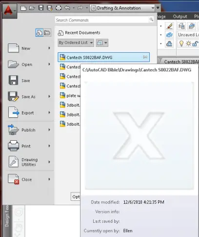
You’ll see the same problem in the list of recent drawings when you click the AutoCAD button as you see here on the right.
Important: While we don't collect cookies, some of our 3rd-party services (such as PayPal and WordPress) do, to give you a safer and better browsing experience. Read about how we use cookies and keep your personal information secure by reading our Privacy Policy here.