Do you have so many layers that you spend too much time rummaging through them? You can filter the layer list so that you see only what you want to see. One advantage to this is that you can then easily select several layers and makes changes to the group, all at once. For example, you can change the color of all the selected layers.
You can create two types of filters:
Properties filter: You define the filter by the properties of the layer, such as blue layers that start with the letter N
Group filter: You define the filter by selecting layers for the group. In other words, you can choose any layers you want and put them in a group.
Follow these steps to create a properties filter:
Open the Layer Properties Manager.
If you don’t see the filter tree panel, right-click in the dialog box and choose Show Filter Tree.
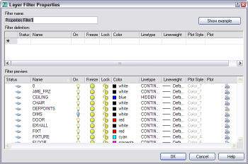
Click the New Property Filter button. The Layer Filter Properties dialog box opens.
Enter a name in the Filter Name text box.
To filter according to a property, click in that property’s column. Depending on the property, either an ellipsis button or a drop-down arrow appears. Click the button or arrow to specify the property. For example, when you click in the Color column, you click the ellipsis button, which opens the Select Color dialog box where you can choose a color.
To filter according to a property with a name, such as a layer’s name or linetype, you can use wildcards. An asterisk (*) replaces any number of characters and a question mark (?) replaces any single character. For example, to find all layers that start with N, enter n* in the name column.
The preview pane shows the results of your filter. Click OK to display the filter in the Layer Properties Manager.
To create a group filter, follow these steps:
Open the Layer Properties Manager.
If you don’t see the filter tree panel, right-click in the dialog box and choose Show Filter Tree.
Click the New Group Filter button. The words Group Filter1 appear in the filter tree panel, selected.
Immediately enter a new name for the filter.
Choose a filter that displays the layers you need, such as All.
Drag the layers that you want onto the group filter’s name.
To add layers by selecting objects that are on the layers you want, right-click the filter and choose Select Layers > Add.
In the drawing select objects that are on the layers and end selection.
Click the group layer filter to see the result in the Layer Properties Manager.
Jack Foster contributed a menu item that makes sure a layer is on, thawed, unlocked and exists — in other words, that you can use it. He says, “When working on a drawing that other users have worked on, you may find that the layer you need is off or frozen. Even if the layer doesn’t exist, this routine will create it. His example is for a layer named “pipe.”
When you create blocks (also called symbols to insert into a drawing, you need to consider what layer to use for the components that make up the blocks. Your choice depends on the results you want and you have four choices:
Component Properties
Insertion Results
On any layer (except 0); color, linetype & lineweight set to ByLayer
Block keeps properties of that layer. AutoCAD creates the layer if necessary when you insert it into another drawing. If the layer exists in the drawing but has other properties, the block takes on the properties of the layer in that drawing. If you insert the block on a different layer, it keeps its original properties, but is reported (in Properties window) as being on the insertion layer.
On any layer (including 0); color, linetype & lineweight set explicitly
Block keeps color, linetype & lineweight that were set. AutoCAD creates the layer if necessary when you insert it into another drawing.
On any layer (except 0); color & linetype set to ByBlock
Block takes on the layer and properties of current layer. AutoCAD creates the layer as necessary when you insert it into another drawing.
On layer 0; color, linetype & lineweight set to ByLayer or ByBlock
Block takes on the layer and properties of the current layer. No new layers are created.
Al Pfennig wrote in this tip: “When creating symbols for inserting into a drawing when the same symbol may be inserted on more than one layer, create the symbol on the zero (0) layer and have color, linetype and linewidth set to ByLayer. This will allow the symbol to take on the characteristics of the layer on which it will be inserted.”
Sometimes you need a list of layers to quickly see all the layers and their status in a drawing. You can share it with colleagues. For a simple method, follow these steps:
Type -layer on the command line.
Choose the ? option to get a list of layers and press Enter.
Press F2 to open the Text Window.
Select the layer list.
Right-click and choose Copy.
Open a text editor such as Notepad. (Start > Run. Type Notepad and click OK.) You can use Microsoft Word or another word processor, but the columns won’t line up as nicely.
Press Ctrl+V or choose Edit>Paste.
Choose File>Print.
If you want to share layers and layer states (settings) with others, save a Layer State file. Choose Layer Properties Manager, click Save State. You can export this file and send it to others. They can import the file to reset layers and their states.
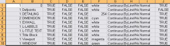
Mike Pool sent me a tip from an associate of his, Jeff Mohr — another way to get a list of layers and their properties. Open the Layer Properties Manager and select the layers you want to list (or press Ctrl+A to select them all). Press Ctrl+C, open Microsoft Excel, and press Ctrl+V. You’ll get a nicely laid out list.
You can modify more than one layer at a time. In the Layer Properties Manager dialog box (click Layers on the Object Properties toolbar) right-click and choose Select All or Clear All. Choose a range of layers by clicking the first layer, holding down Shift and clicking the last in the range. Choose multiple individual layers by pressing Ctrl as you choose each additional layer. Changes to color, linetype, or lineweight affect all the selected layers. And don’t forget that you can sort the listing by any column. For example, if you want to change all your red layers to magenta, click the word “Color” at the top of the Color column to sort all your layers by color. You can now easily select all the red layers to change their color.
Groups are a feature that help you select several objects together, without putting them into a block. You can turn the group on and off, to allow you to select individual objects in the group. Also, any one object can belong to more than one group — another advantage compared to blocks.
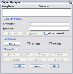
For AutoCAD 2011 and earlier, you use the GROUP command (command line only) to open the Object Grouping dialog box.
To create a group, you enter a name and description, click New, select the objects, and click OK.
Starting with AutoCAD 2012, choose Home tab> Groups panel> Group, then select the objects, give the group a name if you want, and press Enter to end the command.
When you need to edit the group, you can simply type g at the Select objects: prompt and enter the group name. to select it. Or, you can select the group first, by picking it. Groups highlight just like any other object (or block) when you pass the cursor over any object in the group.
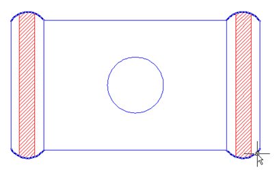
For example, when I wanted to hatch the holes on the left and right, I discovered that the vertical lines weren’t exactly touching the 4 arcs; that meant that I wasn’t getting the right hatch area. To fix the problem, I used the EXTEND command and selected the group as the boundary edge. That made the extending process much quicker.
To modify a group, whether to change the selection status (on or off), add or delete objects from the group, explode it (which deletes the entire group), or rename it, start the GROUP command and choose the group from the list at the top of the dialog box. The buttons in the Change Group section become available and you can click the operation you want.
Remember that the Selectable checkbox or button turns selectability on and off. When it’s off, the group still exists, but you can select individual objects and can’t select the group as a whole. You can turn off the selectability of all group in a drawing by choosing Tools> Options, click the Selection tab, and unchecking the Object Grouping check box.
Tip:Jennifer Grande reminded me that you can press Ctrl+Shift+A to turn groups on and off.
In this tutorial, I’ll expand on the idea of using fields in attributes, which are labels attached to blocks. This example shows the use of fields that label geometric parameters of dynamic blocks.
Open the Block Editor. (Tools> Block Editor or Blocks & References tab> Block panel> Block Editor.
Create the objects for the block.
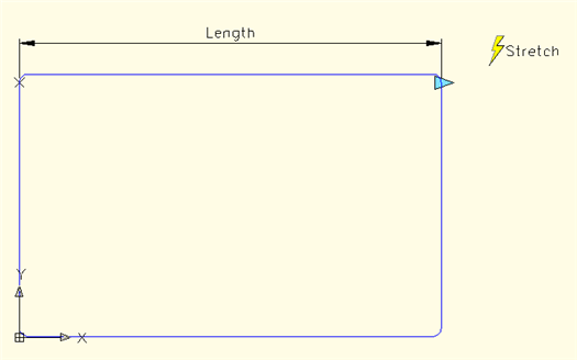
Create the parameter and action you want to label. For example, for a desk, I created a Linear Parameter and a Stretch Action. I renamed the Linear parameter’s label to Length in the Properties palette. If you need further instructions, you can download my complete dynamic blocks tutorial from my “Dynamic blocks tutorial” page.
Start the ATTDEF command (Draw> Block> Define Attributes or Blocks & Reference tab> Atrtributes panel> Define Attributes).
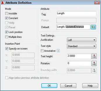
In the Attribute Definition dialog box, type in a tag name, such as Length. For the Deafult entry, type the text that you want to appear before the value, such as Length: . (Add a space after the colon.) Check the Constant check box so that you won’t get a prompt. The whole point is to make the label automatic. Set the Text Settings section as desired.
Then right-click in the Default text box or click the Insert Field button at the right to open the Field dialog box. From the Field Category drop-down list, choose Objects. Then choose BlockPlaceholder as the field name. The Block reference property should be the name of the parameter you used. This is Length in our example. Set the format as desired, and click OK.
Note: The Length property is on the list only because I created a parameter named Length. The other properties are available for all blocks.
You’re now back in the Attribute Definition dialog box, which should look like the figure below. Click OK. Place the label where you want it.
Save the dynamic block by clicking the Save button in the Block Editor. Close the Block Editor.
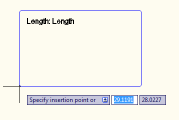
Back in your drawing, insert the block (Insert> Block or Blocks & References tab> Block panel> Insert). Before you specify the insertion point, you’ll see the following for the label.
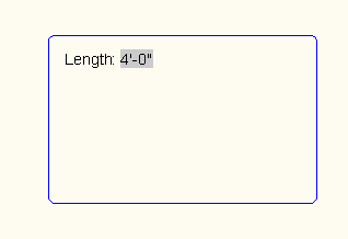
After you insert the block, you’ll see the value of the field.
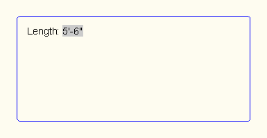
After you modify the dynamic block, you’ll need to update the field. In this example, changing the length makes the desk longer. Enter updatefield on the command line to update the field.
Since AutoCAD 2009, you can record macros for later use. You can include requests for user input and messages to make the macro work interactively.
When you save a macro, it has an ACTM filename extension. You’ll find it in your Support\Actions folder of your AutoCAD installation. You can share ACTM files with others.
Start by thinking about the conditions that you’ll need when you run the macro. Will you be in model space or paper space? The macro doesn’t keep track of all of the current settings. If a certain setting is necessary, use the system variable or the SETVAR command while recording the macro to make sure that you have the setup you’ll need at playback time.
Action Recorder macros have some limitations:
You can’t open files
You can’t grip edit or use PRESSPULL
You can’t load VBA files
Macros also don’t record changes to a dialog box, which means that you may need to use the command line version of a command. If you’ve worked with scripts, you’re familiar with this type of functioning.
You may find other limitations.
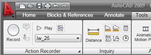
You’ll find the Action Recorder on the Tools tab, in the Action Recorder panel. You can also choose Menu Browser (the A button)> Tools> Action Recorder.
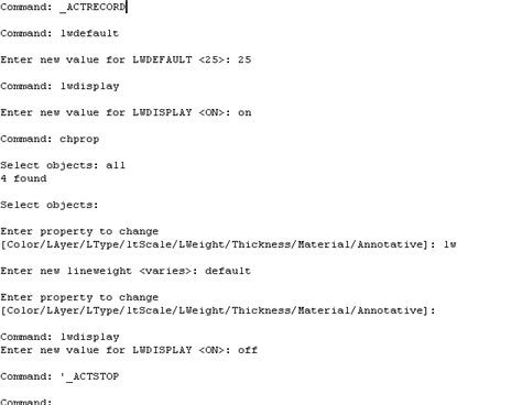
Here’s an example of how you would create a macro to change all objects to the default 0.25mm lineweight. You might get drawings from a company that adds lineweights to objects. Moreover, their default might be different. So this macro sets the default to 0.25, turns on the display of lineweights, and then uses the CHPROP command to change the lineweight of selected objects to the default. At the end, the macro turns off lineweight display.
Figuring out which commands to use often involves some research. For example, I knew that I could turn the lineweight display off and on using the button on the status bar, but I couldn’t do that in the macro, since I didn’t know which way the display would be when I played back the macro. If I wanted to turn the display on, and it was already on, clicking the button would turn it off! So I needed to find the system variable involved, which was LWDEFAULT. Then, it was easy to turn it on and off as needed.
When you’ve figured out the steps that you want to take, and tried them out a couple of times in different situations, you’re ready to record.
Choose Tools tab> Action Recorder panel> Record. Your cursor now has a red dot, to show you that you’re recording.
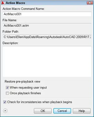
Go through the steps that you practiced. When you’re done. click the Stop button that has replaced the Record button. You now have the opportunity to name and save the macro, as well as choose a few options.
Here is the command line that I created as I recorded:
Because I specified all at the Select objects: prompt, the macro will always select all objects. I tested that by adding more objects with a non-default lineweight; they were also changed.
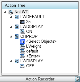
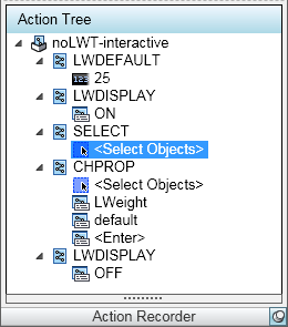
Here’s what the macro looks like in the Action Recorder drop-down window:
I might want to be able to select individual objects. Letting the user select objects makes the macro interactive, and it’s a very helpful feature.
To do this, I reorganized the macro and used the SELECT command before the CHPROP command. While recording, I simply picked any objects. For the CHPROP command, I then used the p (Previous) option at the Select objects: prompt. When I was done, the macro looked like this:
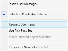
Then I right-clicked the Select Objects item, and chose Request User Input, as shown below:
When I ran the macro, I got a dialog box asking if I wanted to provide user input. By accepting that option, I was able to either select objects, or enter all.
Do you use the Action Recorder? Leave a comment about how you use it!
Question: B.N. asks how he can get his AutoLISP routines from an earlier release into AutoCAD 2007 so that they’re always loaded and ready to go.
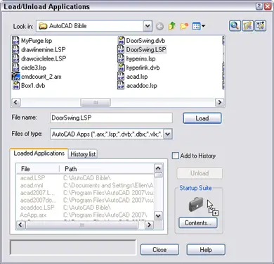
Answer: An easy way is to type the AutoLISP routines in a file and save it as anything.lsp. Then choose Tools> AutoLISP> Load Application. Browse to anything.lsp and drag it to the Startup Suite, which has an icon of a suitcase. Then it will load whenever you start AutoCAD.
Do you need a way to integrate flexible display into your plots? For example, you may want to produce draft plots that use less ink. Or you may want to plot all in black, or shades of gray. You may want to change solid fills to hatches for some plots.
The way to create multiple plot variations is to use plot styles. You can create as many variations as you want, save them, and use them for any drawing. Plot styles are saved in plot style table files.
There are two kinds of plot style tables: named (*.stb) and color-dependent (*.ctb). Named plot styles are more flexible, but are not the default type of plot style. Your choice of plot style table type is saved in the Windows registry, not in the drawing. To switch, you change the type and then open a new drawing.
In this tutorial, I’ll show you how to create and use a color-dependent plot style that sets the lineweight to 0.05 and the screening to 25%. Screening specifies the amount of ink used for a color and the default is 100%. Setting the screening to 25% is a useful technique for saving ink for a draft plot.
Set the plot style type
To set the plot style type, follow these steps:
Right-click in the drawing area and choose Options to open the Options dialog box. Then click the Plot and Publish tab.
Click the Plot Style Table Settings button.
In the Plot Style Tables Settings dialog box, choose Use Color Dependent Plot Styles or Use Named Plot Styles. You can also specify a default plot-style table other than the standard acad.ctb (color-dependent) or acad.stb (named) plot style. For this tutorial, choose Use Color Dependent Plot Styles, if it isn’t already selected.
Click OK.
Create a color-dependent plot style table
You’re now ready to create a color-dependent plot style table.
Choose Application button>Print> Manage Plot Styles to open the Plot Style Manager. You’ll see a Windows Explorer window, like the one you see here. Notice the Add-A-Plot Style Table Wizard shortcut and the other plot style table files that come with AutoCAD — including one that sets screening to 25%.
Double-click the Add-A-Plot Style Table Wizard shortcut to open the Add Plot Style Table wizard.
Click Next.
On the Begin screen, choose the source for your plot style table. For this tutorial, choose Use an Existing Plot Style Table and click Next.
In the Browse File Name screen, choose acad.ctb, which is the default plot style table. Your new plot style table will be based on this one. Click Next.
In the File Name screen, enter a file name. I used Draft-screen-lwt. Click Next.
On the Finish screen, click the Plot Style Table Editor button. The Plot Style Table Editor opens.
You’ve now created a color-dependent plot style table and you’re ready to define a plot style for that table.
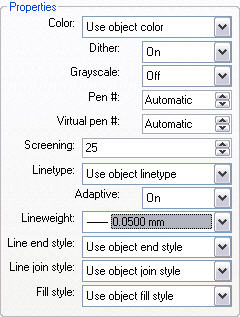
In the Plot Style Table Editor, click the Form View tab. On the left you see all the colors from 1 to 255. You can select more than one color and make changes on the right to apply those changes to all selected colors.
Click Color 1 (red). Use the scroll bar to scroll down to the last color, Color 255 (white). Press and hold Shift and click Color 255. This selects all the colors.
For the Screening item, change the value to 25.
For the Lineweight item, choose 0.0500.
Click Save & Close. You’re now back in the last screen of the Add Plot Style Table wizard.
Click Finish.
You’ve now created a plot style. If you need to edit it, you can access it from several places. One option is to open the Options dialog box as described above and click the Plot and Publish tab. There you can choose Add or Edit Plot Style Tables. You’re now ready to apply your plot style.
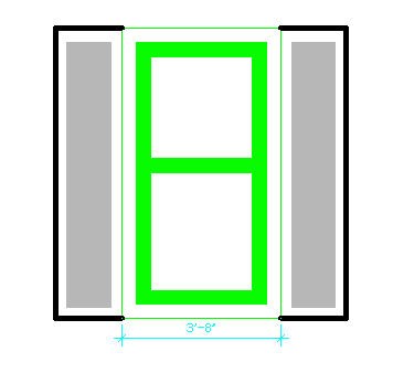
Here’s the drawing. You can see that it uses solid fills in two places and a heavy lineweight around the window shutters.
Attach a plot-style table to a layout
You need to attach a plot-style table to a layout. You can attach different plot-style tables to different layouts to easily create plot variations. Follow these steps:
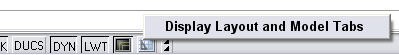
Open a new drawing and draw some objects. In this case, draw an object with a wide lineweight and fill a closed area with a solid fill, so you will see the contrast when you apply the plot style. Choose a layout tab in your drawing and set up one or more viewports. (If the layout tabs are not displayed, right-click the current layout’s button on the status bar and choose Display Layout and Model Tabs, as shown here.)
Right-click the layout tab and choose Page Setup Manager.
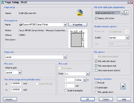
In the Page Setup Manager dialog box, choose an existing page setup, if you have one, and click Modify. Otherwise, click New, name the page setup and click OK. You now see the Page Setup dialog box for the layout.
In the upper-right corner, choose your plot-style table from the Plot Style Table (pen assignments) drop-down list. For this tutorial, you choose Draft-screen-lwt.ctb.
Just below, check the Display Plot Styles check box. With this box checked, you’ll see the effect of your plot styles on your layouts. (If the Display Plot Styles check box is already checked, you’ll need to use the REGEN command to display the plot style.)
Click OK.
In the Page Setup Manager, make sure that the page setup is selected and click Set Current.
Click Close to return to your layout.
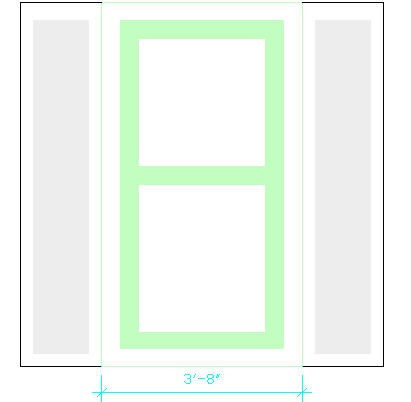
You should now see the results of your page style. Compare the layout below with the drawing I showed earlier.
You can see that the solid fills are much lighter and the lineweight is lighter as well. That will save lots of ink!
Important: While we don't collect cookies, some of our 3rd-party services (such as PayPal and WordPress) do, to give you a safer and better browsing experience. Read about how we use cookies and keep your personal information secure by reading our Privacy Policy here.


 or a drop-down arrow appears. Click the button or arrow to specify the property. For example, when you click in the Color column, you click the ellipsis button, which opens the Select Color dialog box where you can choose a color.