Dynamic blocks, introduced in AutoCAD 2006, are very powerful, but sometimes they can get complicated. One of the more involved features of dynamic blocks is chaining. In this tip, I try to make chaining easy.
Sometimes, you want one action to execute a second action at the same time. If the relationship between the two actions is simple and direct, you can accomplish this easily — without chaining. You just attach two actions to the same grip on the same parameter. When you grip-edit one action, the other happens at the same time.
For example, in this desk set, the desk has a linear parameter and a stretch action attached to the right grip of the parameter. The top-right chair has a move action attached to the same grip. The bottom chair also has a move action attached to that same grip, but the distance multiplier is set to 0.5.
So when you stretch the desk, the top chair moves the same distance, always remaining lined up with the right side of the desk. The bottom chair moves half the distance, always remaining centered behind the desk.
But, your geometry may require more than one parameter. To activate one action with another in this situation, you use the chaining feature. Note that the secondary parameter, the one whose action will be activated by the primary action, must be a point, linear, polar, XY, or rotation parameter. There are some other limitations, too, but they’re hard to explain, so just experiment.
Remember that you want one action (with its parameter) to activate another action, also with a parameter. So you need two actions and two parameters. Create a chained parameter as follows:
Create the block and open it in the Block Editor.
Decide on the parameters you’ll need and their actions.
Decide which action you’ll grip-edit in the drawing. This is the primary action that will activate the other, secondary, action.
Create both parameters first, before creating any actions.
Create the primary action and attach it to its parameter (the primary parameter).
When you specify the objects for the primary action, include the parameter of the secondary action. This is very important. But don’t include the objects that will be in the selection set of the secondary action.
Create the secondary action, attach it to its parameter, and select its objects.
Select the secondary parameter, open the Properties palette, and set its chaining property to Yes.
To summarize, the basic principles of chaining are as follows:
The primary parameter has an action whose selection set includes the secondary parameter in addition to any other objects it will act on. (If the action is a stretch action, the stretch frame also needs to include the secondary parameter.)
The secondary parameter’s chaining property is set to Yes.
Save your block, close the Block Editor and try out your chained dynamic block. When you grip-edit the primary action, the secondary action will be activated at the same time.
As you drag the primary parameter’s grip, the secondary parameter’s grip moves in response to the result of the primary action. For this reason, chaining is useful when you want to maintain a constant relationship between two components in a block.
In this cover, the handle needs to stay the same distance from the top of the cover. The cover comes in three sizes (the linear parameter has a value set) and has a stretch action. As the cover is scaled, the handle moves up.
Note: Once you’ve perfected your block, you can remove the grips from the secondary parameter, because you don’t need them. In the Block Editor, select the secondary parameter, right-click it, and choose Grip Display > 0.
The move action is attached to the top grip of its linear parameter. As the cover is scaled, this parameter (the secondary parameter) moves up, thereby moving the handle.
When you work in 3D, you need ways to view your drawing quickly and effectively. Here are my best tips. What are yours? (Leave a comment!)
Transparent 3D Orbit: Shift + Mouse wheel. This is my all-time favorite 3D viewing tip. If you aren’t using this, you’re wasting time. It lets you easily drag the view in any way.
Switch between parallel and perspective views: Right-click the ViewCube and choose the one you want. I just discovered this.
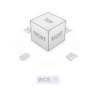
ViewCube: This new tool is a great way to quickly choose one of the standard viewpoints. But did you know that you can drag the ViewCube? Click on a face or corner of the ViewCube and drag in the desired direction.
Plan view: To quickly go to the Top view in the current UCS, type plan and press Enter twice.
Return to plan view when you change the UCS: Set the UCSFOLLOW system variable to 1. Then, when you change the UCS, your drawing switches to plan view.
View the bottom of your model: By default, 3D Orbit uses a constrained mode that doesn’t let you freely orbit around the bottom of your model. It limits you to the XY plane or the Z direction, but not both at once. To remove the constraint, right-click while in 3D Orbit and choose Other Navigation Modes> Free Orbit (in AutoCAD 2011), or just type 2.
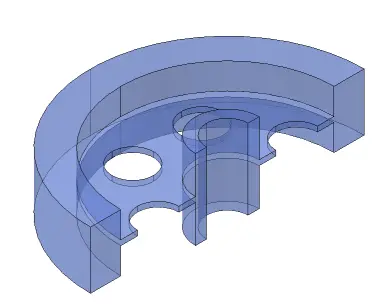
X-ray vision: In AutoCAD 2011, there are new standard visual styles and a useful one is X-ray. It sets the opacity of faces to 50% so you can get a sense of depth (unlike a wireframe style), but still see the entire model.
I just had to share his comment with you, so I asked for, and received, his permission. Here’s what he wrote:
“I can’t tell you how long I’ve been trying to figure out Named Plot Styles but your book (AutoCAD 2011) did it! Go to Pg 516 and read the last sentence under the heading “Named Plot Styles” near the top of the page – the light came ON! [The sentence is “Therefore, two objects of the same color can be plotted differently.”]
While Named Plot Styles probably aren’t for everyone they solve a particular problem I have in my practice and that is as an Electrical Engineer I am more often than not working over another Engineers’ or Architects’ drawing which I typically screen to about 40%. Try that with .ctbs’ when you’re dealing with another’s drawing that may have hundreds of layers and almost everything is a multi level block of some kind!
So, I’m also enjoying your many other insights throughout the rest of the book – it’s SO MUCH more than a command reference – but it’s that too.
Creating, inserting, modifying, and replacing blocks
Creating and using attributes
Creating annotative blocks
Creating dynamic blocks, including visibility states, parameters, and constraints
Extracting data from blocks
Best practices examples
Managing and sharing blocks
The book is only $10 and he’s offering a 40% discount with the CN2010 code. It’s only good until December 31st, which is why I wanted to get this post out to you now. That makes the book only $6!
I suggest that you take a look by clicking this link. (Full disclosure: I make 30% commission.) He also has 2 e-books on Revit, if you’re interested.
I asked Edwin some questions to learn more about him and why he chose this topic:
Q1: Why did you decide to focus on AutoCAD blocks?
I believe that to be productive in AutoCAD, we need to focus on three areas: having good templates, good libraries, and good customizations. Customization need programming knowledge, and not many people can create a program. But AutoCAD blocks are quite simple to create.
I have seen that AutoCAD blocks today can be really useful, not only as reusable content, but also to automate some tasks. By optimizing blocks, we not only become more productive, but also reduce human errors in our design.
Q2: Tell me a little about your background.
I worked in Architecture consultant for a couple of years, then I moved to a building contractor. So I’m familiar with the design process and how we use AutoCAD in that area. I saw that many people tried to create custom programs to be more productive. Then I started to work at an Autodesk reseller, so I had more chances to explore AutoCAD features. I started to see that much of the automation can be done in AutoCAD without any programming. One feature that we can use is AutoCAD blocks. For example, we can use dynamic blocks and data extraction.
Q3: You have 3 e-books, one on AutoCAD and two on Revit. Why did you decide to start writing? Are there any other books on AutoCAD in the pipeline?
I started to write on my blog since 2004. My first blog was written in Indonesian. Some of the readers asked if I could provide the contents in e-book format. It was not easy and expensive to have an Internet connection at that time. I thought it was a good idea. So I decided to also have e-books, especially for materials that can’t be covered in blog posts. At the moment I only have one AutoCAD e-book, but I have plan to cover more about AutoCAD best practices. Wish me luck!
AutoCAD calculator (the QUICKCALC command )is a great feature for both simple and complex calculations. One of the great features is the ability to calculate coordinates.
QuickCalc has variables (or functions) that are shortcuts to some of the more complex coordinate calculations. To use these functions, follow these steps:
Start a command.
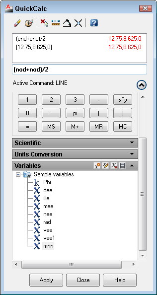
At the prompt where you need the function, type ‘quickcalc (or ‘qc).The QuickCalc window opens.
From the Variables list, double-click the function that you want to place it in the Input box of the QuickCalc window.
Press Enter. You return to your drawing and see a pickbox cursor.
Pick the required points, most commonly by object snaps. The QuickCalc window returns, and you see an absolute coordinate in the Input box.
Click the Apply button.
Continue the command.
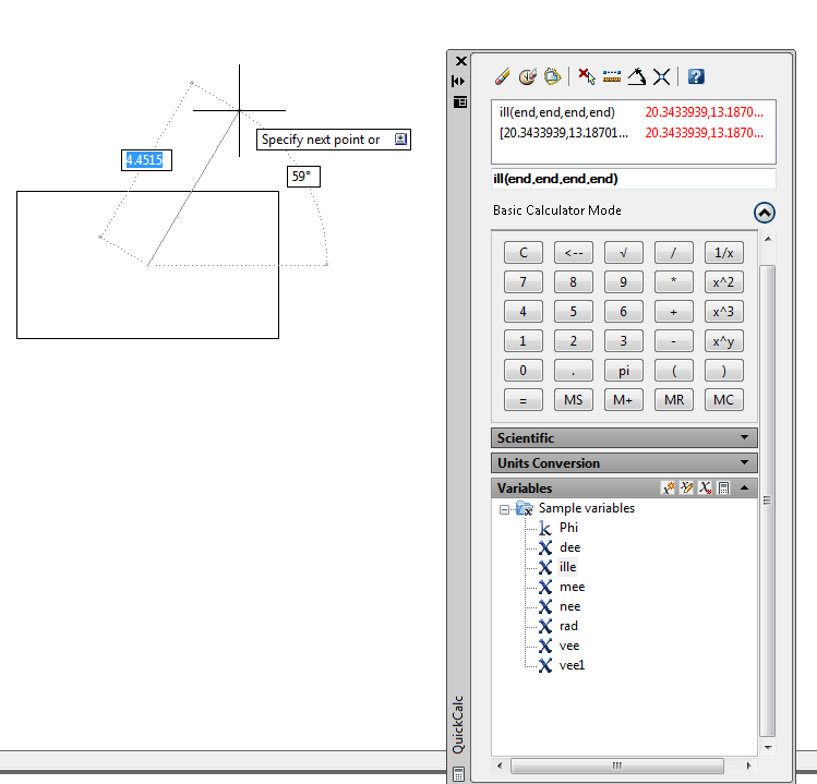
For example, let’s say I have a rectangle and I want to start a line at its center, defined as the intersection of the two diagonal lines drawn from opposite corners. Here’s one way to do that:
Start the LINE command.
At the Specify first point: prompt, type ‘qc.
From the Variables list (you might have to expand the QuickCalc window to see it; then expand the Variables category), double-click ille.
Press Enter. You return to your drawing with a large pickbox.
Pick the first set of diagonal points, such as the upper-left, then the lower-right corners of the rectangle.
Pick the second set of diagonal points, such as the upper-right, then the lower-left corners of the rectangle.
Click the Apply button in the QuickCalc window.
Your line’s start point is now set at the center of the rectangle and you can continue the command.
Create a custom function
When you click a function, you see a tooltip giving you the full format of the function. You can use this format to create your own functions. For example, mee (midpoint between two endpoints) is (end+end)/2. So, to find the midpoint between two nodes (rather than two endpoints), you would use (nod+nod)/2.
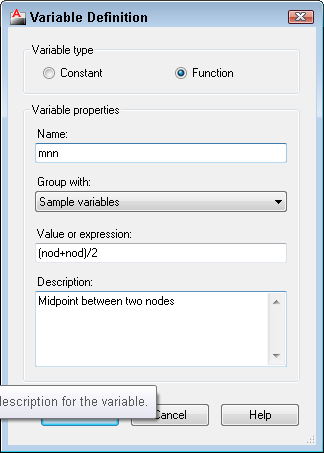
To save your custom function, click the New Variable button at the top of the Variables section. The Variable Definition dialog box opens, where you can define and save the variable.
Then, your custom variable appears on the list and you can use it like one of the variables that come with AutoCAD. You can see mnn at the very bottom of the list.
How cool is that? Have you created a custom variable? Please share it in the comments.
Dynamic Input is a way of specifying coordinates near your cursor, instead of on the command line. It’s on by default, but you can turn it off using the Dynamic Input button on the status bar.
When you’re doing simple drawing tasks, there isn’t much difference between having Dynamic Input on or off.
But sometimes, the command line gives you information that isn’t in the Dynamic Input box. For example, you don’t see options unless you press the Arrow key on your keyboard or right-click. Watch this video:
Dynamic Input gives you lots of preview clues as you draw or edit that you don’t get when you work with it off.
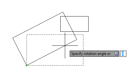
Dynamic Input shows angles differently than you may be used to. With Dynamic Input off, angles are measured counterclockwise, with 0 to the right, ranging from 0 to 360. This is the traditional AutoCAD way of measuring angles. But with Dynamic Input on, some angles are measured from 0 to 180, with 0 to the right, going either clockwise or counterclockwise. Watch the dotted lines near the angle’s tooltip to see exactly what the angle shown in the tooltip is measuring. You can use negative angles. Here’s an example of drawing an arc.
Some default settings in AutoCAD slow down its display and you may want to turn them off or change them. Here are some ideas. Please add a comment to contribute your own display speed tips!
Text
A large drawing with lots of text can slow down your work. Here are some text tips.
Quicktext
Quicktext turns text into rectangles and quickens your regens. Use the QTEXT command and choose on (displays rectangles) or off (displays the text). Then use the REGEN command .
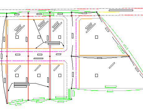
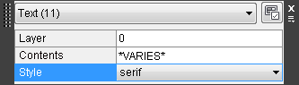
Here you see regular text on the left and quicktext on the right.
Font substitution
Using a simpler font can also speed up your drawing, especially if it’s large and contains a lot of text. Create a new text style that uses one of AutoCAD’s own fonts, rather than TrueType fonts. You can switch back just before plotting. Note that a different font will take up a different amount of space, so the text may not fit properly. Two fonts that are very simple are txt.shx and simplex.shx.
To create a style:
Start the STYLE command.
In the Text Style dialog box, click New.
In the New Text Style dialog box, give the text style a name and click OK.
Back in the Text Style dialog box, choose a font from the Font Name drop-down list.
Change other settings as desired, such as the height, width factor, and oblique angle. You can also make the text style annotative. You’ll see a preview at the lower-left corner of the dialog box.
Click Set Current if you want to use the style right away. Click Close.
An easy way to change all the text in your drawing to your new style is as follows:
Press Ctrl + A to select all objects. If you have Quick Properties on (it’s a button on the status bar), you’ll get a small window showing the properties of your objects.
Click the drop-down list to select Text or MText; this filters out the other objects.
In the Quick Properties window, click the current style and then its down arrow.
Choose a new style from the list.
Press Esc to deselect all the text.
Turn off text layers
You can always turn off text layers. From the Layer drop-down list, click the light bulb symbol next to a layer. Repeat to turn the layer back on.
Solid hatches and lineweights
Solid fills (solid hatches), wide polylines, and 2D solids can take a while to display if you have lots of them. Just use the FILL command and set it to OFF. Use the REGEN command to see the result.
If you’re using lineweights, these are also displayed as solidly filled areas, so you can turn off their display. Just click the Show/Hide Lineweight button on the status bar.
Regens and resolution
AutoCAD automatically regenerates whenever needed, but you can turn off automatic regeneration and manually regenerate (using the REGEN command) when you want to; this reduces regenerations and gives you more control. Use the REGENAUTO command and set it to off.
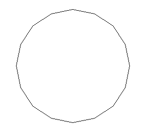
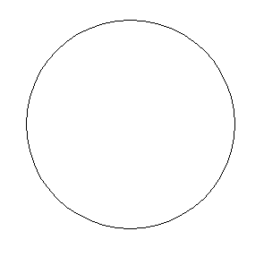
The VIEWRES command sets the resolution that controls circles and arcs. You may have seen a circle that looked like a polygon. Usually, you can use the REGEN command to return its circle-ness. But you can speed up display by lowering the view resolution. Acceptable values are 1-20000. You can set it to 15 for example. A value like 2000 will usually suffice to show you smooth circles again.
When you use this command, you’ll be asked if you want fast zooms. You do. This is a legacy setting.
What are your display speed tips? Add a comment!
Thanks to the guys at Daily AutoCAD for some of these ideas.
AutoCAD for the Mac is coming. Autodesk made the official announcement at the end of August and is expected to ship very soon. Are you interested? Autodesk expects the architectural industry to be most interested in AutoCAD for the Mac. What do you think?
You can get more information at http://usa.autodesk.com/adsk/servlet/pc/index?siteID=123112&id=15421056.
Important: While we don't collect cookies, some of our 3rd-party services (such as PayPal and WordPress) do, to give you a safer and better browsing experience. Read about how we use cookies and keep your personal information secure by reading our Privacy Policy here.