(For AutoCAD 2005 and earlier. For AutoCAD 2006 and later, click here.)
Any time you would like a custom version of an AutoCAD command, you can create a toolbar button for it. It’s very easy to do and will greatly enhance your ease of work and efficiency.Let’s say that you often fillet multiple sets of lines and want to make the mUltiple option the default.
Back up your AutoCAD menu files. To find these files, start the OPTIONS command and click the Files tab. Double-click the Menu, Help, and Miscellaneous File Names item to find the location.
Choose Tools>Customize>Toolbars.
Click New. Name your toolbar (something short and simple) and click OK. You now see a small toolbar on the screen.
Usually, you can start from an existing toolbar button. Press and hold down the Ctrl key and drag any button to the new toolbar. (Holding down Ctrl copies the button instead of moving it.) You can also click the Commands tab of the Customize dialog box and choose a command from the list.
To start from scratch, choose User Defined from the Categories list and then drag the User Defined Button to your new toolbar. Click the button to display its properties. In the Macro Associated with This Button box, enter the macro. Most macros start with ^C^C to cancel any existing command. For information on macro format, go to Tutorial: Create a Custom Command.
Click Apply, then click Close to close the Customization dialog box.
Try out your new button. If you need to edit it, re-open the Customization dialog box and click the button to display its macro.
While AutoCAD comes with a large variety of hatch patterns, you can also create your own. This feature has been around for many years.
Hatch patterns are stored in files with a file extension of .pat. You can add your hatch to the default acad.pat or create your own .pat file. As always, don’t forget to make a copy of acad.pat or acadlt.pat before you edit it.
If you create your own .pat file, here are some points to remember:
If you aren’t adding patterns to acad.pat or acadlt.pat, you can put only one hatch pattern in a custom .pat file; the filename and pattern name must be the same
You can insert comments in your .pat file after a semicolon
You must press Enter after the end of the last line of the hatch definition
Note: To find the location of acad.pat or acadlt.pat, right-click the drawing area and choose Options; then click the Files tab. Double-click the Support File Search Path item to display the location of the support files.
The description is optional; if you include one, precede it with a comma.
Add the dash specifications only for noncontinuous lines.
You can have more than one definition line (the second line in the syntax I just showed), creating sets of hatch definitions that combine to create the hatch pattern.
Each definition line can be no more than 80 characters.
You can include a maximum of six dash specifications (which include spaces and dots).
You can add spaces in the definition lines for readability.
## Dynamic block is another great productivity tip to master. Sign up below to get your Free tutorial on creating a complete dynamic block, including a drawing to practice on. You’ll make a movable chair, resizable desk, and more.
This following explains the meaning of the terms in the definition:
Angle: Defines the angle of the lines in the hatch pattern. If you also specify an angle in the Boundary Hatch and Gradient dialog box when you place the hatch, AutoCAD adds the two angles.
X-origin: Specifies the X coordinate of the base point of the hatch pattern. Your hatch probably won’t go through 0,0; however, this point lines up sets of lines in hatch patterns, as well as aligning hatch patterns in different areas. Because all hatch patterns are calculated from the base point, they’re always aligned, no matter where they actually appear in the drawing.
Y-origin: Specifies the Y coordinate of the base point of the hatch pattern.
Delta-x: Specifies the offset of successive lines. This applies only to dashed lines and is measured along the direction of the lines. Specifying a delta-x staggers each successive line by the amount that you specify so that the dashes don’t line up.
Delta-y: Specifies the distance between lines, measured perpendicular to the direction of the lines. This applies to both continuous and dashed lines.
Dash: Defines a noncontinuous line using the same system as linetype definitions: positive for a dash, negative for a space, and 0 for a dot.
This hatch has an angle of 105 degrees, an origin of 0,0, a delta-x of 0, a delta-y of 0.5 (the spacing between lines), and then defines a non-continuous linetype (dash, space, dot,space,dot,space)
This hatch pattern has 4 lines. Two are at 0 degrees, and two are at 90 degrees. This creates the rectangular shape. The difference between the two lines that start at 0 degrees is their origin. The second one starts at 0,1.5. The 90-degree lines also have different origins. The linetype for the 90-degree lines is dash, space, dot, space, dash, space.
See how the effect of trailers is created?
Have you created a great hatch pattern? Share it by leaving a comment!
You probably have a shortcut to AutoCAD on your desktop. If you do, you can customize how that shortcut works. You can even create several shortcuts and tell them to open AutoCAD in different ways. This is called using command-line switches.
First, select the shortcut and press Ctrl+C. Then press Ctrl+V to create a duplicate. Let’s say you want the new shortcut to create a new drawing with a specific template and workspace. Name the shortcut something like AutoCAD 2007 acad3d.dwt. (Acad3d.dwt is the default 3D template.)
Right-click the new shortcut and choose Properties to open its Properties dialog box.
The Target text box contains the current command. This is what Windows executes when you double-click the shortcut. Notice the quotation marks around it; these are necessary whenever any part of the command has spaces. In this case the Program Files and AutoCAD folders have a space.
Click to the right of the last quotation mark and press the Spacebar. Then you add your switches.
Here’s a list of all the possible switches you can use:
/b opens a drawing and runs a script on it. You need the full drawing path. Example: /b “c:\drawings\clients and odd jobs\Jones” /b setup. Notice the quotation marks around the path because of the spaces.
/ld loads an ARX or DBX file. For example, /ld compare.dbx
/nohardware disables hardware acceleration.
/nologo opens AutoCAD without displaying the splash screen. This saves you at least a second.
/nossm opens AutoCAD without the Sheet Set Manager.
/p opens AutoCAD with a saved profile. Example: /p ellen. You need to have saved the profile.
/pl publishes a drawing set description (DSD) file
/r resets AutoCAD to the default configuration file.
/s specifies support folders (when you want to use support files that aren’t in AutoCAD’s support file search path). Separate folders with a semi-colon (;) without spaces between them.
/set opens AutoCAD and the named sheet set. For example, /set sanchez-house
/t opens a new drawing based on a template. Example: /t b-arch. This is the one we want for our example.
/v opens a drawing with a specified named view. Example: c:\drawings\3479a.dwg /v elevation. Of course, the view needs to exist.
/w opens AutoCAD with the specified worksheet. Example: /w ab3d. This is the other one we want to use for our example.
In this tutorial, I’ll explain the steps for creating a new toolbar using the Customize User Interface dialog box. This dialog box is new for 2006 and the method of customizing toolbars, menus, etc. is very different from previous releases.
Choose Tools>Customize>Interface, or type cui on the command line.
Click the drop-down list at the top of the Customize User Interface dialog box and choose custom.cui. This is a partial customization file and lets you create a toolbar without fiddling with your main menu file.
Right-click the Toolbars item in the main panel of the dialog box and choose New>Toolbar.
The new toolbar, named Toolbar1, appears under the Toolbars item. It is selected, so immediately rename it.
To see the toolbar in the drawing area, click Apply. It’s very small, because it doesn’t have any buttons yet.
The easiest way to add a button is to drag a command from the Command List panel at the bottom-left section of the dialog box. However, the AutoCAD commands don’t all appear because you are now working with the Custom partial customization file. From the drop-down list at the top of the dialog box, choose All Customization Files.
Unfortunately, this collapses the new toolbar that you created on the list. To find it again in the top pane, double-click Partial CUI Files, then double-click CUSTOM, then double-click Toolbars. You should now see your new toolbar.`
From the Categories drop-down list in the Commands List pane, make sure that All Commands is chosen.
Scroll down to a command that you want to add (they’re alphabetical) and click it. Tip: You can type the first letter of the command to jump to the first command starting with that letter.
Drag the command up to your toolbar, until you see a small left arrow pointing to your toolbar. Then release the mouse button. This adds the command to your toolbar.
Continue to drag commands. You can drag them above or below the first button.
You can create your own button if the command you want to use doesn’t have one. For example, the ALIGN doesn’t have a toolbar button. To create a button, select the command in the upper pane of the dialog box. Then click the Edit button in the Button Image section.
Use the Button Editor to edit an existing button or create one from scratch. To edit an existing button, click one of the buttons in the Button Image section. Use the tools at the top and pick a color along the side to draw. Use the Eraser tool to erase.
When you’re done, click Save As and save the button as a BMP file. Remember the location! Click Close to exit the Button Editor. Here’s my ALIGN button.
To assign the image to the button, click the Small Image item in the Properties pane. Click the Ellipsis button and browse to your BMP file.
To create a new, custom command, click the New button in the Command List section.
In the Properties section, complete the command name, a description, and the menu macro. Choose an image or create one in the Button Editor.
You’ll see the new command on the Command List. Drag it to your toolbar.
Click Apply to see the toolbar. You may need to move the dialog box. If you like it, click Close. Otherwise, make any desired adjustments. Here’s my final toolbar, enlarged. It contains buttons for the EXTRUDE, REGION, and ALIGN commands and a custom command that uses the ROTATE3D command to rotate the selected object around the X axis.
If you have custom menus that you have been using for inserting blocks, you know that creating and maintaining these menus is a major project.
If you have a digitizing tablet, you may be using the Tablet 1 section of the tablet menu. If you change a block, you need to edit the menu, create a new image, edit tablet.dwg, and finally replot tablet.dwg to place the new version on your digitizing tablet.
Or you may have created a slide library with slides of your blocks and your customized commands. You may have put the slide library images in an image-tile menu that you display from a pull-down menu item that you have created. Making changes involves editing the menu, recreating the slide, editing the slide list, and recompiling the slide library from the command line.
In both scenarios, you needed to reload the new menu.
A simpler method is to use tool palettes. A reader, Ronald E. Walker, asked me several questions about the new tool palettes and together we worked out the following procedure. He has used slide libraries in the past and is converting them to tool palettes. First I explain the steps for AutoCAD 2005. Afterwards, I explain what you need to do in 2004.
Steps for 2005
In the drawing containing the block, type PNGOUT. (This command creates a PNG file, one of the file types that the tool palettes uses to create the icons. It creates small, accurate files.)
In the Create Raster File dialog box, name the file and choose a location in your support file search path. Click Save.
At the Select objects: prompt, select the block.
Right click in an open area of a tool palette and choose New Tool Palette to create a new tab.
Right-click an open area of the new tab and choose Customize. In the Customize dialog box, click the Commands tab.
Click and drag any command from the Commands area on the right side of the dialog box to the Tool Palette. (The exact command is not important, because you will edit it.)
In the Tool Palette, right click the command tool and choose Properties. The Tool Properties dialog box opens, shown here.
In the Command String item, enter your command string. You can copy and paste from your menu.
Change the name and description in the appropriate text boxes.
Right click the image in the upper left corner of the dialog box, as shown here, and choose Specify Image. (You may just see a square.)
Navigate to the PNG file you saved earlier and click OK.
Click OK to close the Customize dialog box.
Note, if you don’t see the image clearly, you may need to crop it in an image editor.
Editing the tool palette is easy. Just edit the Command String to change the macro. However, if you change the block, you need to update the image. This process is not automatic. The easiest method is to right-click the tool, choose Properties, and right-click the image. Choose Select Image, choose a different image, and click OK. Then repeat the process with the correct image to update the image.
Steps for 2004
In 2004, you need to work directly with the .atc files that create the tools. To find their location, choose Tools>Options and click the Files tab, and double-click Tool Palettes File Locations. In that folder you’ll find a Palettes folder containing the .atc files plus an Images folder that contains the images used by the icons.
The .atc file is a text file that you can modify. It has many codes that I certainly can’t figure out, but for a command tool palette, the important parts are the tool name, image file, and the macro that executes the command. Here is an example of a command tool palette that simply executes the line command.
AutoCAD 2005 changed the COPY command so that it defaults to a multiple option, continuing to prompt you for more locations for your selected objects. On the other hand, the FILLET and CHAMFER commands now have a multiple option, but it isn’t the default. Would you like to change the COPY command back to its single version? Or, if you have an earlier version of AutoCAD, would you like to have the multiple option as your default? Would you like the FILLET and CHAMFER commands to default to the multiple option? Here’s how:
The COPY Command
You can change the COPY command back to its original way of functioning in two ways:
1. Redefine the COPY command. It turns out that AutoCAD has remembered the old functioning as its core definition. You can put the following in acaddoc.lsp (which you can create if you don’t have one), making sure that acaddoc.lsp is in your search path:
The period before the copy command retrieves the core definition.
2. You can also create a new toolbar button and add the following macro to it:
^C^C_select;\_copy;_previous;;\\;
Note: The current toolbar macro comes with some DIESEL code that lets COPY work with grips, so just replace the last part of the macro. (Don’t delete the final closing parenthesis.) The total macro would look like this:
As you probably know, you can add commands to a tool palette. Before AutoCAD 2007, you could only do this by choosing Tools > Customize > Tool Palettes to open the Customize dialog box. Then you could drag commands from toolbar buttons.
Now, you can also drag commands from the Customize User Interface dialog box. Just right-click the Tool Palettes window and choose Customize Commands. This opens the Customize User Interface dialog box.
Then just drag commands from the Command List section of the dialog box onto any tool palette. If you want, choose Custom Commands from the Categories drop-down list — this is a great way to get custom commands onto the tool palette.
Tharakesh of HOPE Technologies Ltd. in Mumbai, India submitted the following tip.
When using the 3DORBIT command, the portion that you want to see may be hidden by another portion. In that case, before invoking the 3DORBIT command, select the object in which you are interested. Then 3DORBIT displays only the selected object. It’s cool! This also works for the 3DCORBIT command (3D Orbit with the Continuous orbit option).
One of the awkward parts about 3D drawing is the fact that you need to constantly change the XY plane. In the past, the only way to do this was to create a new UCS using the UCS command.
Since 2007, however, you can use the dynamic UCS feature, which makes the process of drawing on a plane other than the XY plane much easier. The dynamic UCS creates a temporary XY plane so you can draw or edit on that plane.
Dynamic UCS works only on solids. You turn it on by clicking the Allow/Disallow Dynamic UCS button on the status bar (or by pressing F6). If you find that the dynamic UCS feature sometimes interferes with your work, you can override it temporarily by pressing Shift+Z during an operation.
When you determine that you need to draw on a face of a solid object that’s not on the XY plane, follow these steps:
Start a command. The commands you can use are 2D and 3D drawing commands, text commands, INSERT, XATTACH, editing commands, and grip-editing.
Pass the cursor over the face of a solid. You see a dashed border, as shown here, defining the new, temporary plane.
Then complete your command.
Here, I created a cylinder in the side of the table and finished it off by subtracting the cylinder from the box.
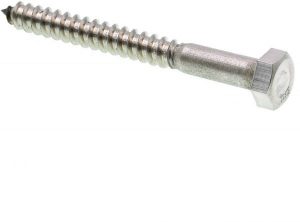
A common, but difficult task, is to create a threaded bolt. I recently got a request for more 3D tutorials, so here you go. This tutorial assumes an intermediate knowledge of AutoCAD.
I rummaged around a box of miscellaneous junk and found this bolt. It’s about 3 inches long.
Follow these steps:
Start a new drawing using acad3d.dwt as the template. Set the visual style to 3D Wireframe and the workspace to 3D Modeling.
Type plan to see the view from the top.
Create a new layer, object, and make it blue.
Start the POLYLINE command, specify a start point anywhere in the middle of the screen, and draw segments as follows:
3<180
3/16<90
.5<0
1/4,-1/16 (this will be a diagonal line whose delta X = 1/4 and delta Y = 1/16
2<0
Close
Note: Close the polyline ensures that you’ll get a solid rather than a surface when you revolve. You’ll need the solid for later operations, such as UNION.
Start the REVOLVE command and select the polyline. Revolve it along the 3-unit line, for the default 360 degrees.
To get a fuller look, set the ISOLINES system variable to 8 and use the REGEN command.
Just to see the result, switch to the SW isometric viewpoint.
Then, switch to the Left viewpoint. You should be viewing the bolt from the top.
Start the UCS command and use the View option to create a new UCS. If you want, save it.
Return to the SW Isometric viewpoint again. You’re still in the new UCS. This will help you create the bolt’s head.
Start the CYLINDER command. The center should be the center of the revolved solid’s top. Use the Diameter option and set it to 9/16. The height is 0.25.
Create a polygon of 6 sides. The center is the bottom center of the cylinder, use the Circumscribe About Circle option. The radius = 9/32.
Use the EXTRUDE command to extrude the hexagon to the top of the cylinder.
To create the beveled top, draw a circle at the top of the cylinder, with the same 9/32 radius.
Extrude it, using the Taper Angle option. The taper angle = -45 degrees, the distance is -0.5, to extrude it downward.
Use the INTERSECT command and choose the extruded, tapered circle and the extruded hexagon, and you should see the familiar look of the head of a bolt. Here you see it in the Conceptual visual style.
To create the threads, start the HELIX command. The center is the center of the circle at the top of the thread area. The base radius is any quadrant of the same circle. Press Enter to set the top radius to the same as the base radius. Use the Turns option and set the turns to 14. For the axis endpoint, pick the center at the bottom of the rod, before it tapers to a point.
Switch to the World UCS and use the PLAN command. Turn the viewpoint so that the end of the helix is at the top or bottom. Below, you see it at the bottom. Use the UCS command with the View option.
To create the triangular shape of the thread, start the POLYGON command and set it to 3 sides. Set the center to the endpoint at the end of the rod. Use the Inscribed in Circle option. Set the radius to 1/16. If the endpoint of the heliix is at the bottom, as you see here, you need to rotate the triangle 180 degrees. It should look like the figure here. The point of the triangle needs to be facing outward from the rod of the bolt.
Start the SWEEP command and select the triangle. Use the Alignment option and set it to No. Then select the helix as the sweep path.
Use the UNION command to combine all the objects. Here’s the result in the 3D Hidden visual style.
Here’s the result with the Framing Steel material. I expected it to be silver but it came out coppery. It looked so good that I left it. For an excellent set of 3D tutorials, go to JD Mather’s site.
Related tips:
* Tutorial: Draw a 3D threaded bolt-video tutorial (See a video of this tutorial!) * 3D Tutorial: Draw a glass * Carve a solid with a surface
Draw and edit faster and easier with these top 25 productivity tips every AutoCAD user should know. Check out “Top Productivity Tips Every AutoCAD User Should Know” at http://www.ellenhelps.me/25-Productivity-Tips
Important: While we don't collect cookies, some of our 3rd-party services (such as PayPal and WordPress) do, to give you a safer and better browsing experience. Read about how we use cookies and keep your personal information secure by reading our Privacy Policy here.