A workspace defines your user interface — which toolbars, menus, and palettes (including the command window) appear, and where. Workspaces are a great feature because you can save multiple workspaces to reduce the time you spend fussing with these objects — opening them, closing them, and moving them around.
AutoCAD comes with default workspaces and you can change those or create your own. In fact, the default workspaces are pretty useless unless you have a huge screen; they leave so many items open that there’s no room to draw!
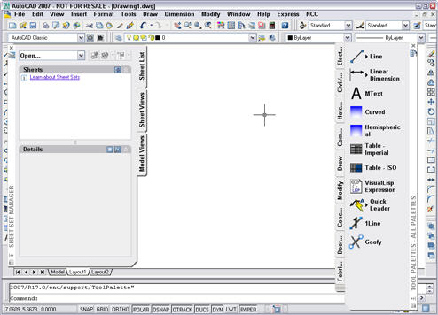
Here’s is AutoCAD 2007’s AutoCAD Classic workspace — at least I think so. It’s possible that I changed it and forgot.
Follow these steps:
Close all the items that you don’t want. In this example, I don’t want the Sheet Set Manager or the Tool Palettes.
Display all the items that you want. Remember that this includes toolbars (including custom toolbars), palettes (such as the Properties and Tools palettes), and menus.
Set up the screen just the way you want it. Remember to not only display the items, but dock or hide them the way you want.
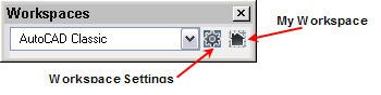
If the Workspaces toolbar isn’t displayed, right-click any toolbar and choose Workspaces.
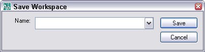
From the Workspaces toolbar drop-down list, choose Save Current As to open the Save Workspace dialog box.
Either enter a new name to create a new custom workspace, or click the down arrow to choose an existing workspace (if you want to redefine it).
Click Save.
If you chose an existing workspace, choose Yes at the dialog box asking you if you want to replace the workspace.
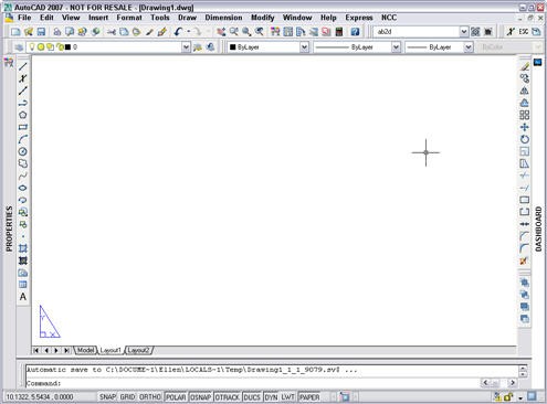
Here you see my preferred workspace: the Properties palette docked and collapsed at the left, the Dashboard docked and collapsed at the right (although sometimes I leave it uncollapsed), my choice of toolbars, including the Workspaces toolbar, and a small custom toolbar at the upper right corner.
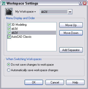
A couple more steps will make the workspace feature even more useful: choosing a Home workspace. On the Workspaces toolbar, click the Workspace Settings button to open the Workspace Settings dialog box.
From the My Workspace drop-down list, choose your new workspace or another workspace.
If you want, in the Menu Display and Order box, you can change the order in which the workspaces appear by choosing any workspace and clicking the Move Up and Move Down buttons. You can also uncheck a workspace if you don’t want it to appear on the list.
Click OK. You can now use the My Workspace button on the Workspaces toolbar as a shortcut to instantly switch to your Home workspace.
Note: You can also create a workspace in the Customize User Interface dialog box. (Use the CUI command.)
If you find yourself using the same combination of commands and options over and over, you can easily create a custom command that executes the combination with a click of a button or a menu item. In this tutorial, I explain the basics of AutoCAD’s menu syntax so that you can create your own commands. No programming required!
Enter cui at the command line/dynamic tooltip to open the Customize User Interface dialog box.
In the Command List pane, click New (Create a New Command).
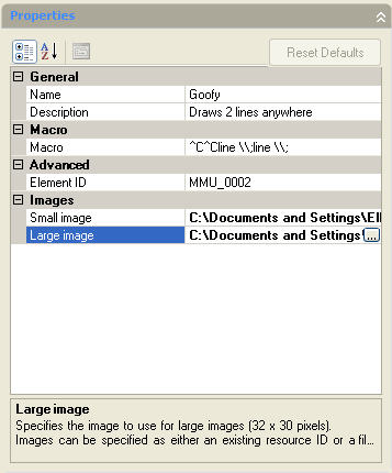
In the Properties pane, enter a name for the command in the Name text box. Also enter a description in the Description text box.
If you think your command will be long or need more than one line, click in the Macro text box and then click the Ellipsis button that appears on the right. Then enter your macro in the Long String Editor dialog box. Otherwise, enter the macro in the Macro text box. Start by writing out the combination of commands and options as you would enter them on the command line or in a script. Then add any necessary special characters.
Below are the special characters you need to know for menu macros:
Character
Description
Space
Equivalent to pressing Enter except when entering text to create a text object that contains spaces (between words). Use between the command and its options.
; (semi-colon)
Equivalent to pressing Enter. The end of a line in a menu macro is also equivalent to pressing Enter. More helpful than using a space when you need to press Enter twice, because it shows the number of Enters more clearly. Also helpful at the end of the macro.
\
Pauses for user input, such as picking a point or entering a value.
+
At the end of a macro line, continues the macro to the next line
*
At the beginning of a macro, before ^C^C, repeats the macro until you press Esc or choose another menu item.
^P
Toggles the display of the menu macro on the command line; makes the macro look neater when you use it.
From the Command List Categories drop-down list, choose Custom Commands to easily find your command. Select it and drag it to the desired menu or toolbar at the top of the Customize User Interface dialog box.
If you drag it to a toolbar, use the Button Editor to give it an image. Usually, you choose an existing button to start with, click Edit, and modify it. Then click the Save As button to save the icon image.
AutoCAD is a complex program and it’s crucial for your work. Obviously, the better you know how to use the program, the quicker and more accurate your drawings will be. This is where the importance of education comes in.
Education has two parts:
Learning more about the base AutoCAD features that you use, or could use.
Keeping up with new releases as they come out
Some organizations upgrade only every few years. I sometimes get e-mails from people who are upgrading from R14 to R2008! But many upgrade every two or three years, which means that education is a regular feature of the job.
Autodesk has a subscription program in which you pay an annual fee and automatically get every new release. Additional benefits are “extensions” (new features released between major releases), e-learning tools, and Web-based support. While companies on the subscription program get each release as it comes out, they don’t necessarily install and use it. But they generally upgrade more often than companies not on the subscription program. Even with the e-learning tools, retraining becomes a feature of life.
How can you learn as much as possible about AutoCAD and also keep up with new releases?
Basic learning resources
When you first learn AutoCAD, it may be from your dealer, from a book, or from on-the-job training. But it’s never enough. Why?
You forget a lot of what you learned, because you don’t use it every day.
New tasks arise and you need to discover the best method of completing them.
There’s always pressure to be more competitive, which completing tasks more quickly. Therefore, you need to regularly incorporate new customization and automizing techniques.
Problems arise, whether due to the melding of drawings from many sources, network issues, having to incorporate multiple software applications, etc.
Here are some resources when you need to learn a new feature, answer a thorny question, or just find a better way:
Your peers: If others in your organization use AutoCAD, ask them first. They may have figured out what you need to know.
Books: Always have a good reference book on hand. The answer may be as simple as looking in the index or table of contents. (Shameless plug: Look on the right for links to my books.)
Discussion groups: The Autodesk AutoCAD discussion group is very active and will often give you an answer within an hour or two.
User groups: There are many AutoCAD user groups around the country and the world. Go to AUGI (Autodesk User Groups International) to search for the one nearest you. Their site is also a great source of support.
Courses: Many colleges, especially community colleges, offer courses in AutoCAD. The schedules are often geared around working people, so you can take them in the evenings or on weekends. Bonus: The teacher and other students can become a permanent networking resource. You can also purchase video courses.
Events: Autodesk University (annually) and CAD camps (several times a year) are great learning opportunities that offer classes specialized by discipline.
Newsletters: Several newsletters, including mine (AutoCAD Tips Newsletter), offer regular tips, techniques, and articles. Subscribe!
Web sites: There are loads of Web sites, too many to mention. Just start searching and you’ll find many. They have free code to download, free tips, and lots more.
Updating your skills
There are several things you can do to specifically help you with new releases. Most of these are time-dependent, matching the cycle of the new software:
Beta programs: You can apply to participate in the AutoCAD beta program, which evaluates the software before it’s finalized. You need to have some time to commit to this, as you’re usefulness is related to the amount of testing you do and comments you submit. You’ll learn the new features before they go to market, giving you a jump on the training process.
Upgrade training: Most dealers offer upgrade training for each release. Ask your dealer about it.
New feature articles: Just after a new release comes out, many sites and newsletters publish a description of the new features.
If you’re a subscription member, you’ll have access to e-learning content for the new release.
Succeeding in the AutoCAD world means being a perpetual learner. Hopefully, this list will help you find the best learning tools.
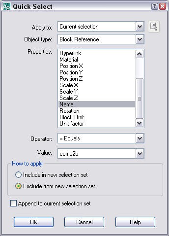
If you would like to see where all the instances of your comp2b block are, you can select them all using the Quick Select feature from the Properties palette. This is a great technique for troubleshooting your blocks.
Follow these steps:
Open the Properties palette.
Click the Quick Select button to open the Quick Select dialog box.
For the Object Type, choose Block Reference. (If you select one of the blocks first, this will already be chosen for you.)
For the Property, choose Name.
For the Operator, choose = Equals (the default).
For the Value, choose the block’s name from the drop-down list.
AutoCAD wants you to keep your templates in the Template folder, but you may have different ideas. For example, you may have custom templates that you want to keep in a separate location.
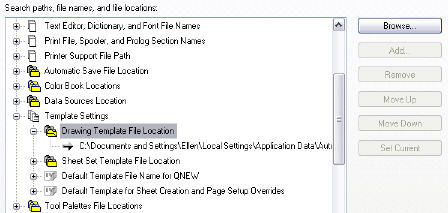
However, in the Files tab of the Options dialog box (Tools > Options), you find that you can’t add an additional location for a template, because the Add button is not available, as you see here.
You can get around this limitation by creating a shortcut to another folder in the Template folder. You do this in Windows Explorer. Follow these steps:
Find the folder where your AutoCAD templates are stored. Open the Options dialog box, click the Files tab and expand the Drawing Template File Location item as shown above.
Browse to that location in Windows Explorer.
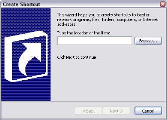
In Windows Explorer, choose File > New > Shortcut. The New Shortcut wizard opens.
Click the Browse button and browse to the folder you want to use for your templates. Click OK.
In the wizard, click Next. Type a name for the shortcut and end the wizard. The shortcut appears in the file pane on the right. I created a shortcut to my AutoCAD Bible folder.
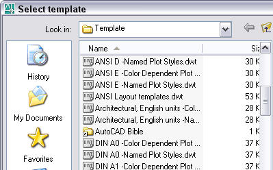
Now, when you choose File > New, you see the shortcut in the Select Template dialog box, as shown here.
Double-click that shortcut to display the templates in that folder.
AutoCAD places your support files in all sorts of hard to find places, such as:
C:\Documents and Settings\[username]\Application Data\Autodesk\AutoCAD 2008\R17.1\enu\support\
Moreover, you can have many folders in your support file search path, including those that you add yourself. (To add a folder to the search path, choose Tools>Options and click the File tab of the Options dialog box. Open the Support File Search Path item and click the Add button. Then click Browse. Navigate to the folder you want, choose it, and click OK. Click OK again to close the Options dialog box.)
To quickly find any file in the support file search path, enter the following on the command line:
(findfile “filename.ext”)
where filename.ext is the name of the file.
Arnold Williams submitted the following AutoLISP expression:
(defun c:FF ( / ) (findfile (getstring “\nEnter Name & Extension of file for Filefind: “)) )
He explains: “Just type in ff and follow the prompt and a path and file name are returned if found, nil if not found.”
AutoCAD comes with a number of linetypes: continuous, dashed (various lengths), dotted, dash-dot, border, center, and so on. But you can make your own. A simple linetype is just a pattern of dashes, dots, and spaces. (A complex linetype can include text and shapes, but that’s another tutorial.)
To create your own simple linetype, follow these steps:
Open Notepad. A linetype file is a text file. Usually you use Notepad to edit it.
There are Two default linetype definition files available in AutoCad: acad.lin for imperial units, and acadiso.lin for metric units. (The files in AutoCAD LT are acadlt.lin and acadltiso.lin.). Navigate to the relevant file for your application. In this example, we use Acad.lin.
For AutoCad 2017 version, the easiest way to find it by cut/paste this location to your file explorer/browser: C:\Program Files\Autodesk\AutoCAD 2017\UserDataCache\en-us\Support. The path will be different for other versions of AutoCAD, of course.
Choose File > Save As and save it under another name, but in the same folder, such as mylinetypes.lin. You can edit acad.lin directly, but be sure to back it up first.
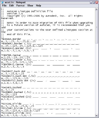
Acad.lin looks like this:
Scroll down to the User Defined Linetypes section at the end of the file. After the comments, enter your linetype definition. Here is the syntax:
A linetype has two lines of text. The first line’s syntax looks like this:
*linetype name[, description]
That means that the first line always starts with an asterisk (*). Then you add the name, which can’t have spaces. The description is optional and limited to 47 characters. If you add a description, precede it with a comma. For example:
*proposed border,3 dashes and a dot – – – .
The second line, which defines the linetype, starts with the letter A. You separate each item with a comma, but no spaces. The maximum length for the second line is 80 characters. Here are your options:
A dash: use a positive number, indicating the length in units
A dot: use a 0 (zero)
A space: use a negative number, indicating the length in units
Press Enter after the second line and save the file.
Go back to your drawing and open the Layer Properties Manager.
Click the New Layer icon and name the new layer anything you want. Assign it any color you want.
Click Continuous in the Linetype column. In the Select Linetype dialog box, click Load.
In the Load or Reload Linetypes dialog box, click File. Select mylinetypes.lin (or whatever you named your file) and click Open.
In the Load or Reload Linetypes dialog box, choose your linetype and click OK.
In the Select Linetype dialog box, choose your linetype and click OK to assign it to the new layer.
Click Set Current and click OK.
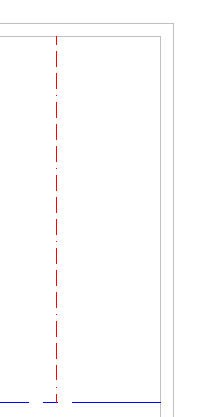
Start the LINE command and use your new linetype!
Ready to explore and learn ways to be more productive and become a master at customizing AutoCAD?
What are the limits and the extents of your drawing?
What are the running object snaps?
What’s the current elevation setting?
Is FILL on or off?
What’s the current linetype?
How much free space does your hard drive have?
How much memory is free?
How many places do you think you’d have to look to find all this information? Think again. It’s all in one place — the STATUS command. It’s an ancient command but packs lots of information.
Try it out — you’ll see a lot more items than the ones I listed.
It’s a great tool for troubleshooting. Try it out. Leave a comment to let others know how you use this command.
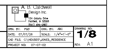
Attributes are tags, or labels, for blocks. You can use attributes to add any text to a block. For example, attributes are often used to fill in the text in a title block.
By placing the attributes where you want them in the title block, you can facilitate the entering of the text. You can also use fields in attributes, to automate some of the text entry.
You can extract the attributes in a drawing to a table or external file. When you do this, you can use the attributes to create a simple database. You could import it into Excel and manipulate it there.
If you’re using attributes to create title block text, you’ll be working in paper space on a layout. If you’re using them to create labels in the rest of your drawing, you’ll be working in model space.
Start the ATTDEF command
Draw the objects that will make up the block. (If you already have a block and want to add attributes to it, you can explode the block, add the attributes, and recreate the block. You can also open the block in the Block Editor, add the attributes there, and save the changes.)
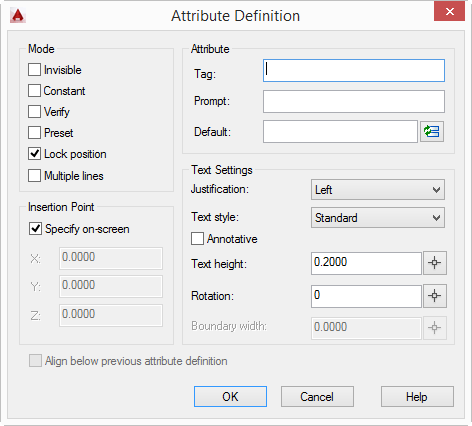
Choose Home tab>Block panel (expanded)>Define Attributes (ATTDEF command) to open the Attribute Definition dialog box.
Configure the Mode section
In the Mode section, check one or more of the following:
Invisible: Creates invisible attributes that you can extract, but don’t want to display in the drawing.
Constant: Sets a constant value so that you don’t need to fill it in each time. You cannot edit this value.
Verify: Prompts you to verify the value, useful when you have a preset.
Preset: Inserts a default value, but you can edit it if you set the ATTDIA system variable to 1.
Multiple Lines: Allows an attribute to contain multiple lines of text. You can also format attributes in a simplified text editor.
Check the Lock Position check box to lock the position of the attribute relative to the block, so that you can’t grip edit it and move it.
Configure the Attribute section
In the Attribute section, specify the Tag, which is like a field/column name for the attribute. For example, enter Cost if the attribute will contain cost information. The tag is converted to uppercase and cannot contain spaces or exclamation points.
Enter a prompt, which is similar to the tag, but can contain spaces.
Enter a value to set a default value. In AutoCAD 2008, this is called the Default. To insert a field, click the Insert Field button.
In the Text Options/Settings section, choose a justification, text style, height, and rotation.
In the Insertion Point section, check the Specify On-Screen check box to specify the location of the attribute. Otherwise, enter the desired coordinates.
Click OK. At the prompt, specify the location if prompted.
Check out this free dynamic block tutorial
Plus get free tips in our AutoCAD Tips Newsletter!
Get a free tutorial on creating a complete dynamic block, including a drawing to practice on. You'll make a movable chair, resizable desk, and more. PLUS, the highly-acclaimed AutoCAD Tips Newsletter will keep your skills up to date!
Choose Make Block on the Draw toolbar (BLOCK command) and use the Block Definition dialog box to create the block. When you select the attributes, separately pick them in the order you want them to appear to prompt you for values. You can choose the Delete option to delete the block and attribute items, because you’ll insert the block later, with its attributes. For instructions on making a block, see “Making a block in AutoCAD.”
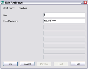
When you’re ready to insert the block, you can specify attribute values on the command line or in a dialog box. The default depends on which AutoCAD release you’re using. To use a dialog box, change the value of the ATTDIA system variable to 1.
Insert the block
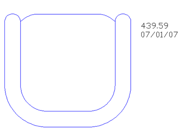
Use the INSERT command to insert the block. For instructions, see “Insert a block in AutoCAD.” If you set ATTDIA to 1, you then see the Edit Attributes dialog box, where you specify values. Otherwise, you see a prompt on the command line. Any default values that you entered are shown in the text boxes.
Enter the desired values and click OK. The block now shows the attributes (unless you set them to invisible).
Draw and edit faster and easier with these top 25 productivity tips every AutoCAD user should know. Check out “Top Productivity Tips Every AutoCAD User Should Know” at http://www.ellenhelps.me/25-Productivity-Tips
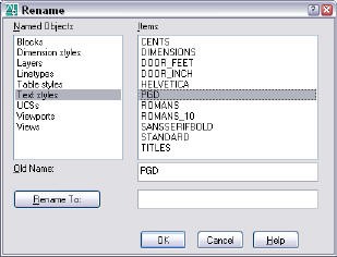
For troubleshooting or collaborative purposes, you may need to know the named objects in your drawings, that is:
Blocks
Dimension styles
Layers
Linetypes
Materials
Table styles
Text styles
UCSs
Viewports (really viewport configurations)
Views
Plot styles (which you see only if you’re using named plot styles)
You can see all your named objects by using the RENAME command. In the Rename dialog box, choose the type of named object you want, and you’ll see all of its items.
Of course, you can also use this command to rename objects; it’s very handy for that purpose.
Unfortunately, while you can select all of the named objects for a category, you can’t copy them to the Clipboard.
Important: While we don't collect cookies, some of our 3rd-party services (such as PayPal and WordPress) do, to give you a safer and better browsing experience. Read about how we use cookies and keep your personal information secure by reading our Privacy Policy here.