AutoCAD’s surfaces have evolved over the years. First, you could add thickness to 2D objects. I’m not sure when that happened (let me know if you do), but it was in the mid-1980s, perhaps around Release 2.6. This is still the only type of 3D objects that AutoCAD LT can create.
Later (again, I’m not sure when), you could create polygon/polyface meshes. The commands were the 3D command, the 3DFACE command, the 3DMESH command, the PFACE command, and others.
Release 2010 introduced, a new type of object, the smooth mesh. The REVSURF (revolved surface), TABSURF (tabulated surface), RULESURF (ruled surface), and EDGESURF (edge surface) commands now create the new mesh objects by default. (You can use the MESHTYPE system variable to create the older polygon mesh surface, if you want.) The new mesh objects offer much greater editing capabilities. For more information, see AutoCAD 2010 new features–scroll down to the “New mesh solids” heading and click the movie’s play button.
Because the older commands are pretty much outdated, I’ll be removing the exercises for them from the next edition of my book. But they’re still useful for people with older versions of AutoCAD and an excellent learning experience for those of you who are new to 3D drawing. So, I’ve decided to publish one of the exercises here.
In this exercise, you use the 3D command’s options to create a table and objects on the table. I assume a medium level of AutoCAD experience.
1. In AutoCAD, click New on the Quick Access toolbar or use the NEW command. Choose acad3D.dwt as the template and click Open. 2. Start the UNITS command. In the Drawing Units dialog box, set the Length unit from the Type drop-down list to Architectural. Click OK. 3. Turn on Object Snaps and set running object snaps for Endpoint and Midpoint. Switch to the 3D Modeling workspace, if your release has it. 4. Enter 3d on the command line and choose the Box option. Follow the prompts to make the tabletop:
Specify corner point of box: 1,1,30 Specify length of box: 4′ Specify width of box or [Cube]: 3′ Specify height of box: 1 Specify rotation angle of box about the Z axis or [Reference]: Press Enter.
If necessary, do a Zoom Extents to see the entire box. If you’re not in a 3D view, change the view to SE Isometric. (Use the VIEW command and choose SE Isometric from the Preset views.)
5. Start the 3D command with the Box option again. Follow the prompts to make a leg:
Specify corner point of box: 1,1 Specify length of box: 1 Specify width of box or [Cube]: 1 Specify height of box: 30 Specify rotation angle of box about the Z axis or [Reference]: Press Enter.
6. Mirror the leg, from one side of the table to the opposite side, using Midpoint object snaps for the mirror line. Then mirror the two legs in the other direction, so that you have four legs. Zoom out and pan as necessary to center the table in the drawing area. (If you have trouble finding the Midpoint object snaps, change the visual style to 2D Wireframe.) 7. Start the 3D command with the Dish option. Follow the prompts to create a bowl on the table:
Specify center point of dish: 2′,2′,35-1/2 Specify radius of dish or [Diameter]: d Specify diameter of dish: 9 Enter number of longitudinal segments for surface of dish <16>: Press Enter Enter number of latitudinal segments for surface of dish <8>: Press Enter
The dish’s diameter is 9, so its height is half that, or 4-1/2. The center of the dish is at height 35@@bf1/2 because the tabletop is at 31 (31 + 4-1/2 = 35-1/2).
8. Start the ELEV command on the command line. Change the elevation to 31. Leave the thickness at 0 (zero). 9. Start the 3D command with the Cone option. Follow the prompts to create a salt shaker:
Specify center point for base of cone: 2′,1′ Specify radius for base of cone or [Diameter]: 1 Specify radius for top of cone or [Diameter] <0>: .5 (That’s 0.5.) Specify height of cone: 4 Enter number of segments for surface of cone <16>: 8
10. Start the 3D command with the Sphere option. Follow the prompts to draw an orange in the bowl:
Specify center point of sphere: 2′,2′,32-1/2 Specify radius of sphere or [Diameter]: d Specify diameter of sphere: 3 Enter number of longitudinal segments for surface of sphere <16>: 8 Enter number of latitudinal segments for surface of sphere <16>: 8
11. Start the 3D command with the Cone option again. Follow the prompts to make a plate. (It may not seem logical to use a cone to make a flat plate. However, it works because you can create a truncated cone that is upside down and very shallow. It’s an unusual but interesting use for the CONE command.)
Specify center point for base of cone: 1′,1′ Specify radius for base of cone or [Diameter]: 2 Specify radius for top of cone or [Diameter] <0>: 5 Specify height of cone: 1/2 Enter number of segments for surface of cone <16>: Press Enter
12. Start the 3D command with the Wedge option. Follow the prompts to make a wedge of cheese on the plate:
Specify corner point of wedge: 10,10 Specify length of wedge: 5 Specify width of wedge: 2 Specify height of wedge: 2 Specify rotation angle of wedge about the Z axis: 30
13. Start the 3D command with the Pyramid option. Follow the prompts to draw a pyramidal pepper shaker:
Specify first corner point for base of pyramid: 2’6,2’6 Specify second corner point for base of pyramid: @1,0 Specify third corner point for base of pyramid: @0,1 Specify fourth corner point for base of pyramid or [Tetrahedron]: @-1,0 Specify apex point of pyramid or [Ridge/Top]: t Specify first corner point for top of pyramid: @1/4,1/4,3 Specify second corner point for top of pyramid: @-1/4,1/4,3 Specify third corner point for top of pyramid: @-1/4,-1/4,3 Specify fourth corner point for top of pyramid: @1/4,-1/4,3
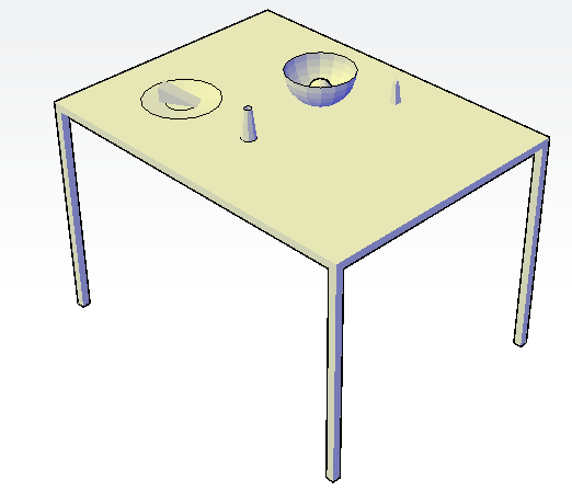
14. Choose Home tab@@>View panel@@>Visual Styles drop-down list@@>Conceptual (the VSCURRENT command). Turn off the grid if it’s on. You can now visualize the drawing better. 15. Save your drawing. It should look like the figure below.
The table with a plate, wedge of cheese, bowl, orange, and non-matching salt and pepper shakers.
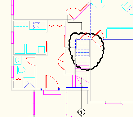
A revision cloud is an often-used means to indicate that certain areas of a drawing contain revisions. The cloud draws attention to the revision. It’s similar to using Track Changes in Microsoft Word, or highlighting text. The revision cloud circles the revised objects.
A revision cloud
To add a revision cloud, choose Home tab> Draw panel (expanded)> Revision Cloud, or start the REVCLOUD command. You see the following prompt:
Minimum arc length: 2′-8″ Maximum arc length: 2′-8″ Style: Normal Specify start point or [Arc length/Object/Style] <Object>:
The first line shows the existing settings. Use the Arc Length option to set the minimum and maximum arc lengths that make up the cloud. The maximum can be up to 3 times the minimum. When you create a range, the result looks more hand drawn. You can pick each arc point to control the size of the arcs, but if your picks are longer than the maximum arc length, AutoCAD creates the arc automatically.
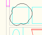
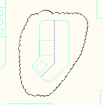
Use the Object option to select an object and place the cloud around that object. The object must be a polyline, spline, or circle.
A revision cloud around an object
You often need to change the arc length to make a revision cloud look good around various sized areas.
Use the Style option to choose either Normal (the default) or Calligraphy, which creates beautiful clouds that look as if they’re created with a calligraphy pen.
A revision cloud using the Calligraphy style
When you’re done with your settings, just drag around the area to draw the revision cloud. When you get back to the beginning, AutoCAD closes the cloud for you. You can end the cloud at any point by pressing Enter; use this technique to create an unclosed cloud. Drawing a revision cloud is different from other drawing tasks because you drag rather than specify start and end points.
Blocks and basepoints go hand-in-hand. Knowing how to work with basepoints can make your life much easier. It’s so frustrating to insert a block and have it disappear into outer space because the basepoint is in the wrong location!
The Basepoint option of the INSERT command
When you insert a block, a Basepoint option appears with the Specify insertion point: prompt. When you use this option, you can move the insertion base point of the block to anywhere you want. This option can be really helpful sometimes but I don’t think it’s used very often.
The BASE command
A block library often has one block per drawing. You save each block in its own drawing. By default, the basepoint of a drawing is 0,0. But unless you put the block right at 0,0, you’ll want to change that. (Another option that works is to use WBLOCK and choose to write just the block. Then, the basepoint is taken from the block and is in the right place.)
Use the BASE command in the drawing containing the block to specify the origin of the drawing, which is usually on an object snap somewhere on the block. Then, when you insert the drawing, your basepoint will be right on the block.
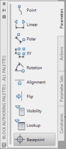
Creating a Basepoint parameter
For a dynamic block, the Basepoint parameter sets a base point for the block. This is useful when you’re turning a block into a dynamic block and want to change the basepoint. You add a Basepoint parameter in the Block Editor, from the Parameters tab of the Block Authoring Palettes, as you see here. The basepoint functions like any other block basepoint.
During insertion of a dynamic block, you can use the Basepoint option as I described earlier.
But you can do something else with dynamic blocks.
While you’re inserting a dynamic block, you can press Ctrl to cycle among the grips if their Cycling property is set to Yes. (By default, it is.) Each time you press Ctrl, the cursor moves to another grip on the block. This lets you visually see the results of each basepoint before you commit to inserting the block.
To check the Cycling property, double-click the block to open the Edit Block Definition dialog box, and click OK to open the Block Editor. Click any grip and open the Properties palette. Look for the Cycling property in the Misc section.
If the Cycling property is set to No, click the item, click the drop-down arrow, and choose Yes.
Do you have any other tips for controlling blocks with basepoints?
Everyone works with layers. Most of the time, you set up your layers in a template and that’s that. But when you need to make changes, a few tips can help make the process easier. Here are some of mine:
Create a similar layer: When you create a new layer, often you want its properties to be similar to that of an existing layer. Select that layer in the Layer Properties Manager and then click the New Layer button. Your new layer will have the same properties as the selected layer and you now have to change only those properties that will be different.
Undo changes to layer settings: Choose Home tab> Layers panel> Previous to undo changes you made to layer settings. It’s like an UNDO comment for the Layer Properties Manager. This is the LAYERP command. It can go back more than one change, but doesn’t uncreate new layers you’ve created.
Turn off layers instead of freezing them: If you’re used to freezing layers that you don’t want to see, you might want to try just turning them off instead. Turning them back on doesn’t require a regeneration.
Save layer states: If you change the states of your layers a lot (on/off, unlocked/locked, etc.) and/or change their properties (color, linetype, etc.) and then change them back, save layer states. Choose Home tab> Layers panel> Layer States drop-down> Manage Layer States or click the Layer States Manager button in the Layer Properties Manager. You can then restore your layer states in the Layer States Manager dialog box.
Use the Express Tools layer commands: Check out the layer commands that were once part of Express Tools but are now in the Layers panel of the Home tab. Some of them are in the extended section, so you have to click the down arrow on the panel’s name. Do you have a favorite?
Change more than one layer at a time: You can modify more than one layer at a time in the Layer Properties Manager. Select the layers you want to change and then click in the row of any of the selected layers, in the column of the property you want to change. For example, to change the color of two layers, select them (press Ctrl and click them), and click the color swatch of either of the selected layers.
Purge layers that you don’t need: The PURGE command has a new feature that helps you figure out why you can’t purge an item. In the Purge dialog box, select the View Items You Cannot Purge option. Then select an item. Below the list of items, you’ll see an explanation. For example, “This layer cannot be purged because it is the current layer.”
AutoCAD 2010 introduced a great new feature, parametric constraints. You can constraint objects in two ways:
Geometrically: You can constrain objects to meet at a point, be horizontal, be vertical, be perpendicular, be concentric, and more
Dimensionally: You can constrain the dimensions of objects. For example, a you can constraint a line to be 4 units long, or two lines to be 4 units apart.
This tutorial, adapted from my book, AutoCAD 2010 & AutoCAD LT 2010 Bible, takes you through the process of constraining the simple model you see here. The goal is to constraint the objects so that all you can do is stretch the model, keeping the relationships the same. However, you want the circle’s diameter to remain unchanged, because it represents a hole for a fixed-size axle.
Parametric constraints in AutoCAD
Starting at Point 1, draw a horizontal line to the left, 4 units long.
Continue to draw a line segment vertically down, 4 units long.
Continue to draw a line segment horizontally to the right, 4 units long. End the LINE command.
Start the ARC command. At the Specify start point of arc or [Center]: prompt, select the endpoint at Point 2.
At the Specify second point of arc or [Center/End]: prompt, choose the End option. Then choose the endpoint at Point 1.
At the Specify center point of arc or [Angle/Direction/Radius]: prompt, press Shift + right-click to open the OSNAP shortcut menu. Choose Mid Between 2 Points. then choose the endpoint at Point 1 and the endpoint at Point 2.
Start the CIRCLE command. At the prompt for the center, specify the center object snap of the arc. Set the radius to 0.75 units.
Click the Parametric tab in AutoCAD 2010. Choose AutoConstrain in the Geometric panel.
Notice that AutoCAD adds the following constraints:
Perpendicular
Parallel
Horizontal
Tangent
Concentric
Coincident
Geometric constraints in AutoCAD
You can see which constraint is which by hovering your cursor over a constraint icon; a tooltip appears with the name of the constraint. Coincident constraints don’t display an icon at first, so put your cursor over the small blue square until the icon appears; then move your cursor over the icon to see the tooltip.
Parametric constraints in AutoCAD
To constrain the three lines to be of equal length, click the Equal button in the Geometric panel of the Parametric tab. Then pick at Point 3 and Point 4 in the model above. Because of the other constraints, you don’t need to constraint the bottom horizontal line.
To fix the circle’s diameter, in the Dimensional panel, click the Diameter button. Select the circle and specify a location for the dimension line as prompted. Press Enter to end the command.
Start the SCALE command and select all the objects in the model. Using the lower-left corner endpoint as the basepoint and 1.5 as the scale factor. The model just moves!! That’s because you’ve constrained the size of the circle.
Undo the SCALE operation.
Repeat the SCALE command. Select all the objects in the model, but this time, press Shift and select the circle to deselect it. Now try the same scaling operation. This time it works.
Now start the STRETCH command. Specify a crossing window (from right to left) from Point 5 to Point 6 in the above model. and again use the lower-left corner as the base point. Drag to the right. Notice that you can’t elongate the model, because the 3 lines are constrained to be equal. You can only scale the model, which is just what you want. The circle stays the same size.
Stretching the model with parametric constraints in AutoCAD 2010
The CHANGE command changes the endpoint of a line and the radius of a circle. The CHANGE command works differently, depending on whether you select lines or circles, so it’s best not to choose lines and circles at the same time.
Note: You can use the CHANGE command to change text , the text and text properties of block attributes (not yet contained in a block), as well as the location and rotation of blocks. Of course, it’s easier to use the text-related commands. The Properties option of this command can change many object properties, but it’s generally easier to use the Properties palette. However, these features of the CHANGE command are useful when writing scripts or AutoLISP code.
Change lines
If you select one line, the CHANGE command changes the endpoint closest to where you picked the line. At the prompt for a change point, specify where you want that endpoint to be. You can use an object snap to specify the change point. If Ortho Mode is on, the line becomes orthogonal, bringing the endpoint of the line as close as possible to the change point that you specify. OK, it’s easier to do this with grip editing.
However, if you select more than one line, CHANGE works differently, moving the nearest endpoints of all the lines to the change point so that all the lines meet at one point.
See it in action!
Change circles
Changing the radius of a circle is the same as scaling it. When you select a circle, the command prompts you for a change point. AutoCAD resizes the circle so that it passes through the new point. You can also press Enter. You then get a prompt to enter a new radius. OK, so it’s easier to just grip-edit it.
But, if you select more than one circle, the command moves from circle to circle, letting you specify a new radius for each, one at a time. You can tell which circle is current because of its drag image, which lets you drag the size of the circle. You can type the radius of each circle.
If you want to make several circles the same size, select the circles and enter the desired radius in the Radius box of the Properties palette.
Layer states let you save configurations of layer properties and states. For example, you might want a layer to be red sometimes, and blue at other times. You may need certain layers to be locked, off, or frozen when you’re editing one part of the drawing, but unlocked, on, or thawed when you’re editing another part.
You could spend lots of time adjusting layer properties, but instead, you can use layer states — they’re much easier and quicker.
Create and restore a layer state
Follow these steps to create a layer state:
Set all of the layer states and properties the way you want them. A good idea is to first save the default, “normal” situation before saving variations.
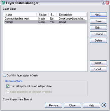
To open the Layer States Manager dialog box, open the Layer Properties Manager and click the Layer States Manager button.
Click New and type a name and description for the layer state. Click OK.
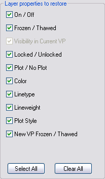
Click the More Restore Options button to expand the dialog box. (In earlier releases, the options are at the bottom of the dialog box.)
Uncheck any states or properties that you don’t want to save. For example, if you don’t save the Color property, the color won’t be affected when you restore the layer state. Therefore, if you change a layer’s color and restore the layer state, the layer will remain the new color.
If you want your drawing to exactly match the way it looks now, check the Turn Off Layers Not Found in Layer State check box in the main section of the dialog box. When you check this box, any new layers that you create afterwards are turned off when you restore the layer state.
Click Close to save the layer state.
You can continue to display desired states and save them until you have all the layer states that you need.
To restore a layer state, open the Layer States Manager, choose the layer state and click Restore.
Share layer states
Layer states are saved in the drawing. To share them among drawings, you need to export them. Each layer state has its own LAS file. To export a layer state, select it in the Layer States Manager, and choose Export. In the Export Layer State dialog box, enter a name, choose a location, and click Save.
To import a saved layer state, open the Layer States Manager, and click the Import button. In the Import Layer State dialog box, choose Layer States (*.las) from the Files of Type drop-down list. Choose the LAS file that you want, and click Open.
You can save layer states in your templates for maximum ease and to maintain CAD standards. Layer states can be an important method for controlling how your drawings look and speeding up the drawing and editing process.
In a previous post, “Create a rectangle with a flexible corner,” I showed how to create a rectangle whose upper-right corner is stretchable, creating a flexible rectangle that doesn’t lose its shape. In this post, I show how to do the same with a dynamic block.
Thanks to Joel, whose comment to the earlier post helped me figure this out. Watch the video–it’s under 2 minutes.
The faster you can display the section of your drawing where you need to work, the faster you can get started drawing and editing. With that in mind, here are some tips for viewing your drawing:
Use the mouse wheel
The mouse wheel is the key to fast view changes:
You can zoom in and out by rolling your mouse wheel. Roll away from you to zoom in, towards you to zoom out. Did you know that where you place the cursor determines the center of the zoom? You don’t have to click. Just move the cursor to the area of your drawing that you want to zoom in to, and zoom in with the mouse wheel.
You can do a Zoom Extents by double-clicking the mouse wheel.
You can pan by dragging (pressing and holding) with the mouse wheel. Tip: You can pan past the application window and even the edge of your screen. Just keep dragging the mouse cursor.
In 3D drawings, press Shift + the mouse wheel and drag to do a transparent 3D orbit.
Save a view
Saving views is especially helpful in large drawings. Set up the view that you want and then use the VIEW command to open the View Manager. Click New and enter a name. Click OK to accept the default of using the current view. Or choose Define Window to return to your drawing to define a view boundary. You can pan and zoom at the same time. Press Enter to return to the View Manager. Click OK to complete the process.
To display a saved view, again use the VIEW command. Choose the view from the list, click Set Current, and click OK.
You can open a drawing to a saved view. In the Select File dialog box, check the Select Initial View check box and click Open. The Select Initial View dialog box opens, where you can choose the view that you want to display when you open the drawing. Click OK.
Specifying an initial saved view when you open a drawing
Use the ViewCube
The ViewCube in AutoCAD 2010
For 3D drawings, the new ViewCube is a handy way to change viewpoints. You just click on the face, edge or corner of the cube. You can also drag the ViewCube to make minor changes in your viewport; it’s not that different from 3D Orbit.
Has anyone found the Steering Wheel in 2010 useful?
Automate 3D views
In a comment on the post, Productivity Boost Ideas, someone asked about AutoLISP code for SE Isometric and other viewpoints. You can use the VPOINT command to automate these views. Here are the settings for the VPOINT command:
Top: VPOINT 0,0,1
Bottom: VPOINT 0,0,-1
Left: VPOINT -1,0,0
Right: VPOINT 1,0,0
Front: VPOINT 0,-1,0
Back: VPOINT 0,1,0
Southwest: VPOINT -1,-1,1
Southeast: VPOINT 1,-1,1
Northwest: VPOINT -1,1,1
Northeast: VPOINT 1,1,1
Leave a comment with other tips you have for viewing a drawing!
Note: This is an article by Fran Golding, Senior Drafter at Parsons Brinckerhoff, a large planning, environment and infrastructure firm with offices in Australia and New Zealand. Perhaps you can add your own productivity boost ideas.
When I first started to drive a car, I had the feeling that I was not the one in control. The car was controlling me. It took some
Out of control
time and practice before that changed. Likewise, when I started to use AutoCAD, I had the same feeling. All sorts of things happened which I did not understand. With time and practice (quite a lot of time and practice, I might add), that changed. As with driving a car, I did the same functions, the same way in which I was taught. It wasn’t until I had more confidence in what I was doing that I branched out and tried new ways of doing things. Thence came the beginning of my productivity boost!
Unlike driving a car, AutoCAD performs the same functions in many different ways. You can start the PLOT command by typing plot at the command line, choosing a toolbar or ribbon icon, or choosing File> Print from the drop-down menu (with variations depending on your release and workspace). Any of these will perform the same result. When you are first learning to “drive” AutoCAD, chances are you will generally follow the exact method which you were taught. It’s not until you understand how the program works that you can speed up what you do by creating shortcuts.
I am always surprised to find that users with many years experience still perform functions the long way. Often it depends on what (or who) they have been exposed to at their jobs. It rings true for any trade – if you have an innovative mentor, you will be more innovative! With the technological information super highway we have so much information at our finger tips. There is just no need to plod along doing the same things, the same way, year after year, after year!
“How much difference can it make?” I hear you asking. If we measure key strokes performed in a day, then reduce them by only one key stroke, it compounds to a staggering saving in a year.
To increase your productivity, you don’t need to reinvent the wheel. If you don’t know where to start and you don’t have a resident CAD guru in your office, don’t despair! An Internet search will return countless results. Don’t be put off. Start your journey with that one step. It will lead to the next in a very short time.
Create aliases
The very first step which I took was to add some command aliases to my ACAD.PGP file. Aliases allow you to type one letter at the command line instead of the full word, such as E for Erase, C for Copy or M for Move. They cut out many key strokes. Editors note: In AutoCAD 2010, go to Manage tab> Customization panel> Edit Aliases to customize acad.pgp. You can also open acad.pgp from Windows in a text editor; its location varies according to your release and Windows version.
Part of the acad.pgp file
Write simple AutoLISP routines
The next step which I took was to write some very simple AutoLISP routines. I began my own AutoLISP file which I added to the Startup Suite. This means you do not need to load the routines individually each time you start AutoCAD. Editors note: To add a .lsp file to the Startup Suite, use the APPLOAD command. In the Load/Unload Applications dialog box, locate the file and drag it to the Startup Suite icon.
Drag AutoLISP files to the Startup Suite
Some examples of these very simple routines are getting distance measurements with selected object snaps. For example, I sometimes need to obtain a distance nearest an object or line, then perpendicular to an object or line. The coding for this looks like: (defun C:DNP () (command “DIST” “NEA” pause “PER”))
Then, typing DNP at the command line allows me get the information I need. You might say that you can easily set OSNAPS and achieve the same thing, but the above coding ensures that the correct object snap is used every time. This can often be critical.
Editor’s note: The syntax is (defun C:[name] () (command “DIST” “[osnap]” pause “[osnap]”)) where [name] is the name of the custom command you are creating and what you type to execute it and [osnap] is any object snap you want to use. The pause command stops the execution of the routine for user input, in this case, specifying a point.
From here there are many more such command combinations that you can write using the same syntax, and substituting different object snaps, such as:
DII (distance from intersection to intersection): (defun C:Dii () (command “DIST” “INTERSECTION” pause “INTERSECTION”))
DEE (distance from endpoint to endpoint) (defun C:DEE () (command “DIST” “ENDPOINT” pause “ENDPOINT”))
DEP (distance from endpoint to perpendicular) (defun C:DEP () (command “DIST” “ENDPOINT” pause “PERPENDICULAR”))
Likewise, you can write many AutoLISP routines to draw lines using selected object snaps:
LINE command from Nearest, then Perpendicular to an object or line: (defun C:LNP () (command “LINE” “NEA” pause “PER”))
LEE (line from endpoint to endpoint): (defun C:LEE () (command “LINE” “ENDPOINT” pause “ENDPOINT”))
Editor’s note: Here, the syntax is similar, but uses the LINE command instead of the DIST command.
Once you start writing these, you can easily add others. Even slightly more complex AutoLISP routines will become easy to write. For example, you can write AutoLISP routines to change system variables such as turning wipe out frames on or off.
To turn wipe out frames on: (defun C:WF1 () (command “WIPEOUT” “FRAME” “ON”))
To turn wipe out frames off: (defun C:WF01 () (command “WIPEOUT” “FRAME” “OFF”))
If you look closely at the coding, you will notice that the text inside the inverted commas [quotation marks] is what you would normally type at the command line.
Another series of handy AutoLISP routines is creating frequently used layers, setting their colour and setting them to current. For example, the company I work for specifies that all dimensions are drawn on a layer called “DIMS” which has the color 2 (yellow). The AutoLISP to create this layer looks like: (defun C:D2 () (command “-LAYER” “N” “DIMS” “S” “DIMS” “C” “2” “”))
You can then write extras to add many more layers such as a layer to draw hatches would look exactly the same as for DIMS with the appropriate substitutes. For example: (defun C:H2 () (command “-LAYER” “N” “HATCHES” “S” “DIMS” “C” “2” “”))
My company also has a dedicated layer for inserting external reference drawings called XREF. So, the code to create this and set it current looks like: (defun C:X2 () (command “-LAYER” “N” “XREF” “S” “DIMS” “C” “2” “”))
To fillet lines using a zero radius: (defun C:F0 () (command “FILLET” “R” “0”) (command “FILLET”))
To fillet using a supplied radius: (defun C:FR () (setq rad (getstring “\n Enter Radius:”)) (command “FILLET” “R” rad) (command “FILLET” pause pause) (princ))
Editor’s note: This last routine uses the setq AutoLISP command to set a variable named rad to the result of user input in response to the Enter Radius: prompt. It then uses the result to set the fillet radius.
The key to successfully boosting your productivity is to keep on learning. You will be surprised how much greater satisfaction you will get out of increasing your learning. Greater productivity leads to a win-win situation. Your employer will be pleased, and who knows — that may lead to greater remuneration. In this article, I want to encourage all users to embrace the latest and strive to be more productive each day!
Important: While we don't collect cookies, some of our 3rd-party services (such as PayPal and WordPress) do, to give you a safer and better browsing experience. Read about how we use cookies and keep your personal information secure by reading our Privacy Policy here.