
You can attach other drawings to the current drawing to facilitate the drawing process. For example, you can attach a floor plan to a drawing of an electrical layout to make sure that you put the outlets in the right location. These other drawings are called external references, or xrefs.
Sometimes, xrefs can be large. For example, you may only want to see one room at a time in the floor plan. Or the xref may contain an entire city block and all you want is one house.
For this purpose, you can clip xrefs so that you see only the portion you need. It’s similar to cropping an image in an image-editing program, except that the process is temporary (you can undo it) and doesn’t affect the original drawing at all. Whatever is outside the clipping boundary disappears until you turn off the clipping boundary.
Although many people don’t realize this, you can also clip blocks that you insert into a drawing.
To clip an xref or block, use the XCLIP command. Choose Insert tab>Reference panel> Clip.
Select the xref or block and press Enter to end selection.
At the [ON/OFF/Clipdepth/Delete/generate Polyline/New boundary] <New>: prompt, press Enter to use the New option.
At the [Select polyline/Polygonal/Rectangular/Invert clip] <Rectangular>: prompt, you can do one of the following:
- Press Enter to use the default Rectangular sub-option. Then specify two corners of the rectangle to clip the xref or block.
- Specify the Polygonal sub-option and pick points to specify a multi-sided shape to clip the xref or block
- Specify the Select Polyline sub-option. Then select an existing polyline to use as the clipping boundary.
- Specify the Invert Clip sub-option to clip whatever is inside the boundary and then choose one of the three previous options to specify that boundary.
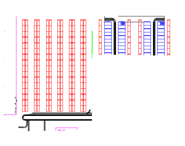
Here you see an xref with a polygonal clip.
Once you have a clipping boundary, you can use the command again and choose the OFF option to re-display the entire xref or block. However, AutoCAD remembers the boundary, so you can use the ON option later on to turn it back on.
The Clipdepth option is for 3D drawings only and specifies front and back planes for the clipping boundary.
The Generate Polyline option draws a polyline from an existing clipping boundary, using the current layer and linetype. You can then edit that polyline using the PEDIT command if you want to redefine the clipping boundary later.

- Combine or subtract 2D shapes to create custom shapes - February 17, 2022
- Working with linetype scales - January 18, 2022
- Rename named objects–blocks, dimension styles, layers, and more - December 21, 2021
 Instagram
 LinkedIn
 Facebook

great! it is really great and helpful.
When I use the crossing window to select items in the vicinity of xclip blocks I am CONSTATNLY unintentionally also selecting the xclip border (even though it is not visible) and thus the xclip block. Thus I often accidentally move or erase xclip blocks. HOW CAN I AVOID THIS??
Hi Bill
Hopefully by setting the FRAMESELECTION variable to 0 will end your frustrations! In since AutoCAD 2012.
It must be the
FRAMESELECTION (System Variable)
Controls whether the hidden frame of an image, underlay, clipped xref, clipped point cloud, or wipeout can be selected.
0 Hidden frames cannot be selected.
1 Hidden frames can be selected.
Note
The FRAME system variable controls whether frames of all types are displayed or hidden.
The PREVIEWFILTER system variable may prevent the frame from redisplaying during selection preview, but the frame can still be selected.
It’s WORK! Wonderful, Thanks
I have a drawing in which I have used a lisp file to insert consecutive numbers. when I xref the drawing into a working drawing the numbers cannot be seen, all layers are turned on, I have used purge and attsync.
any ideas
David is the text/attribute annotative? This could be causing the issue
I have a drawing that is drawn at ¼” scale.
I need to show more detail of certain areas of this drawing so I xclipped portions of it into a new drawing call Details at ¾”.
When I go to include the detail into a sheet border new or old, the only things that show up are the annotations, not any of the xclips themselves.
does xclip larger or havier than when i crop the drawing by deleting the drawings around my area?
XClip objects viewable when being moved
Thank you that was very helpful!
When I insert a floor plan, then clip it to show only some rooms, the insertion point, which is out of the drawing extents, makes “zoom all” zoom out to include the blank area where the insertion point is. If I delete the clipped x-reference, then the “zoom all” works as it should, to drawing limits or extents. Any ideas how to fix this problem? Using AuotCAD LT 2019. Thanks in advance.
When I insert a floor plan, then clip it to show only some rooms, the insertion point, which is out of the drawing extents, makes “zoom all” zoom out to include the blank area where the insertion point is. If I delete the clipped x-reference, then the “zoom all” works as it should, to drawing limits or extents. Any ideas how to fix this problem? Using AuotCAD LT 2019. Thanks in advance.
Hi Humberto,
Must be an issue of base point location for the block or entity. YOu may try:
1. Type BASE in the command line, then specify a point closest to your xref file. Press Enter
If this won’t work, you may use AUDIT and PURGE to clean p the drawings and fix possible errors.