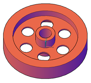
This is a fairly simple wheel with a center tube for an axle/pole, a rim, and 6 holes. You can create a 3D wheel like this entirely with cylinders! Watch this 9-minute video tutorial and follow along to create it from scratch yourself.
You’ll learn how to:
Create cylinders: Cylinders are an obvious choice for a wheel and are often used in mechanical drawings.
Set the workspace to 3D Modeling: The 3D Modeling workspace gives you all the tools you need for 3D work; you won’t find them in the default workspace
Use the SUBTRACT and UNION commands: These are called Boolean commands and they let you carve out holes and combine objects
Change the visual style to check your work: The default wireframe makes some work easier, but it’s really hard to tell if you made mistakes. This image uses the Conceptual visual style, which makes everything very clear.
and a few more tasks.
The basic concepts are applicable to many types of 3D models.
Here’s the video. Let me know in the comments what you think! Do you have suggestions for drawing this differently? Did you run into problems? And use the Share buttons below the post to share with your colleagues so they can practice it, too!
If you have LOTS of drawings and want an easier way to find them, you can give them properties that you can search for using Windows Explorer. You can even create custom properties. You’re supposed to be able to search for these properties in the Design Center and Content Explorer, but neither one worked for me. Of course, you can search for drawings by name, but what if you don’t know the name? What if you don’t know when it was last modified? Drawing properties can help.
Create the drawing properties
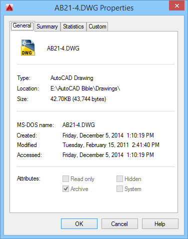
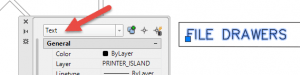
To specify drawing properties, choose Application Button, Drawing Utilities, Drawing Properties. This opens the Properties dialog box. It has 4 tabs:
General: This is just for your information. You can’t add properties here.
Summary: Lets you specify a title, subject, author and add keywords. You can separate multiple keywords with a comma. You can also add comments and a hyperlink base to use for relative hyperlinks.
Statistics: This is also for information only and tells you when the drawing was created and last modified, who last saved the drawing, the revision number (if any), and the total editing time.
Custom: To add custom properties, click the Add button. Then type the custom property name and value and click OK.
Of course, you want to use properties that will help you find the drawing. You might add properties for clients, discipline (architectural, mechanical), geographical location, etc.
Search for a drawing by its properties
To find a drawing by its properties, open Windows Explorer. Then follow these steps:
In the left pane, click where you want to search. It can be a drive or a folder.
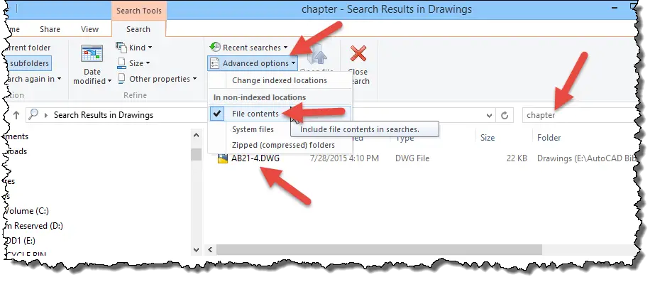
Type a search term in the search box at the upper right. I searched for “chapter,” which was my property. I didn’t have to know its value.
At the top, choose Advanced Options and check File Options.
That found the drawing that contained a custom “chapter” property, as you can see in the figure below.
Why not Content Explorer or Design Center?
I tried searching in the Content Explorer and the Design Center and came up empty. What is your experience using drawing properties? If you don’t use them, would they help you? Leave a comment. And please share this post using the Share buttons below — maybe someone else will find it useful.
Sometimes you want to fill a closed area with a solid color, rather than a hatch, like this. This feature is part of the HATCH command, but you may have missed it. It’s really easy to use.
First set the layer that you want to use for your solid fill. The hatch will go on the current layer.
On the Home tab in the Draw panel, click Hatch. The Hatch Creation tab appears.
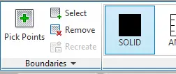
In the Pattern panel, choose Solid.
If you have one closed area, you can just click inside it to pick an internal point. If you want to select an object, you can click Select in the Boundaries panel, as you see here. Then press Enter to end selection.
Press Enter to end the HATCH command.
Turn fills on and off
I thought I’d tell you about the FILL command. This command (which controls the FILLMODE system variable) can show or hide solid fills. Its original purpose was to help your computer run faster if you had lots of solid fills. Nowadays, that isn’t usually a problem, but turning off solid fills can sometimes help you see your objects more clearly.
Just type fill and press Enter. Then choose On or Off. Type regen to see the change.
Warning! If you turn off fills, they don’t plot! So be sure to turn them back on if you turned them off for ease of editing.
The SOLID command that isn’t a solid
The SOLID command is an old command that’s rarely used now because using the Solid pattern of the HATCH command is much easier. It was the original way to fill a closed area with a solid fill, hence the word “solid.” It’s not related to 3D solids, although if you create an object with the SOLID command and give it thickness, it creates surfaces with tops and bottoms.
You can only use SOLID for straight-edged objects. First create the object and turn on object snap for endpoints and whatever else you’ll need. Type solid and press Enter. then start specifying points in a zigzag fashion. After the 4th point, you’ll get prompts for the 3rd and 4th points over and over until you’re done. You continue to create adjacent triangles in this way until the shape is solidly filled. Press Enter to end the command.
If you found this post useful, please use the Share buttons below so that others can learn as well!
AutoCAD offers several types of text or annotation objects. Some are for dimensions or at the end of leaders, for example. But the most common type is text that you use as labels–and there are 2 types. The original type was called single-line text (or Dtext). When you use single-line text, every line is a separate object, ideal for short labels.
But many drawings require lengthy annotation in paragraph form and for that reason Mtext (multiline text) was introduced many years ago. You can format text almost any way you format text in your favorite word processor.
But sometimes, you have single-line text that should be Mtext, or vice versa. I have some old drawings that were created before Mtext! Here are 2 ways to convert between text and Mtext.
Convert single-line text to Mtext
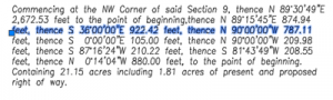
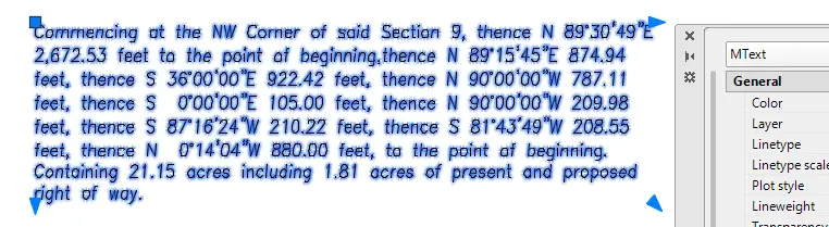
Here’s some text in an old drawing that is single-line text. You can see that one of the lines is selected. It’s a plat description and of course, it should be Mtext. To convert it, use the Express Tools command TXT2MTXT. From the ribbon, choose Express> Text> Convert Text to Mtext.
At the Select objects: prompt, select the text objects that you want to convert. Usually, a window works best for selecting. After all, you don’t want to have to select each line of text individually!
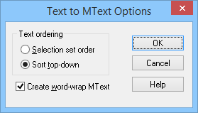
If you press Enter instead, you get the Text to MText Options dialog box, shown here. By default, the command sorts from the top object downward and tries to word wrap the Mtext that it creates. You can choose to order the text by the order you selected it.
One cool feature of TXT2MTXT is that if you select the text objects first, the command executes without further input — very efficient! Also, the command does a true conversion by deleting your old single-line text objects.
You can see that you now have a single MText object.
Convert Mtext to single-line text
Sometimes, you need to reconfigure your text because it won’t fit anywhere as a paragraph. In these situations, you can convert the Mtext to single-line text.
One way to convert Mtext to text is to copy and paste. Double-click the Mtext to open the Mtext editor. Select the text and copy to the clipboard. Then close the editor.
Start the TEXT command. Specify the start point, height and rotation angle as usual. You’ll then see a small box and cursor. Paste from the clipboard and press Enter to end the command. The text becomes all one line (which can get pretty long if you have a lot of text). Then delete your Mtext object.
Or you can simply explode the Mtext. This method keeps the line wrapping. It all depends on which result you want. A plus is that you don’t have to delete the original object.
How do you convert between the 2 types of text? Leave a comment! And help other AutoCAD users by sharing this post with the sharing buttons below.
The Geometric Center object snap is new for AutoCAD 2016. It seems to me that there hasn’t been a new object snap for a long time. Am I right? When do you think that last new object snap was introduced and what was it?
Now that the trivia contest is set, let’s get into it. It’s really very simple. You need a closed polyline to use it.
Start a command, such as the LINE command
Access the list of objects snaps — by pressing Shift and right-clicking or using the list on the status bar. You can also use the keyboard shortcut, GCE.
Choose Geometric Center and click to specify the start of the line.
End the line wherever you want.
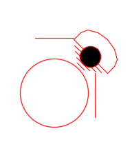
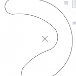
One cool point is that the geometric center doesn’t have to be inside the polyline. In this example on the right, the X marks the geometric center of the closed polyline.
The 1-minute video below shows an example of drawing a line from the geometric center of a closed polyline.
Are you going to use this new object snap? How will it be useful to you? Leave a comment!
This is a guest post from Lee Ambrosius, who was my co-author for the AutoCAD 2015 and AutoCAD 2015 LT Bible. As you can tell from the photo, he’s a runner — even in some pretty cold Wisconsin weather! Lee is both an Autodesk Authorized Developer and Authorized Author. He’s also the author of the upcoming AutoCAD Platform Customization, His website is hyperpics.com
AutoCAD 2016 is the latest in a long line of AutoCAD releases that dates back over 30 years ago. The latest release offers a number of changes that improve 2D drafting operations, rendering 3D models, and much more.
There is a lot to cover, so Lee suggested that we split it up. In Part 1 we started with changes to the user interface and 2D drafting. Part 2 covered annotation and external file changes. Here in Part 3, we talk about new 3D and CAD management features.
This is a guest post from Lee Ambrosius, who was my co-author for the AutoCAD 2015 and AutoCAD 2015 LT Bible. As you can tell from the photo, he’s a runner — even in some pretty cold Wisconsin weather! Lee is both an Autodesk Authorized Developer and Authorized Author. He’s also the author of the upcoming AutoCAD Platform Customization, His website is hyperpics.com
AutoCAD 2016 is the latest in a long line of AutoCAD releases that dates back over 30 years ago. The latest release offers a number of changes that improve 2D drafting operations, rendering 3D models, and much more.
There is a lot to cover, so Lee suggested that we split it up. Part 1 covered changes to the user interface and 2D drafting. Part 2 (this post) covers annotation and external file changes. In Part 3, we’ll talk about new 3D and CAD management features.
This is a guest post from Lee Ambrosius, who was my co-author for the AutoCAD 2015 and AutoCAD 2015 LT Bible. As you can tell from the photo, he’s a runner — even in some pretty cold Wisconsin weather! Lee is both an Autodesk Authorized Developer and Authorized Author. He’s also the author of the upcoming AutoCAD Platform Customization, His website is hyperpics.com
AutoCAD 2016 is the latest in a long line of AutoCAD releases that dates back over 30 years ago. The latest release offers a number of changes that improve 2D drafting operations, rendering 3D models, and much more.
There is a lot to cover, so Lee suggested that we split it up. We’ll start with changes to the user interface and 2D drafting. Part 2 will cover annotation and external file changes. In Part 3, we’ll talk about new 3D and CAD management features.
This week’s very cool guest post is by Jaiprakash Pandey.Jaiprakash is a Mechanical Engineer, Blogger, Corporate trainer and yes, self proclaimed charcoal artist too! He is active on many CAD forums including Autodesk and AUGI forums, and is a certified AutoCAD 2014 professional who has been doing corporate training for three years. You can read more at his blog, SourceCAD.
In this project, solid and surfacing tools have been used to create the 3D model of speaker, LOFT, TORUS , SPHERE, SLICE and PRESSPULL have been used primarily. This project is intended for advanced users. Although a beginner can also follow instructions and make the drawing easily, it is strongly suggested that the beginner explore basic projects before moving to these advanced projects.
Here’s my New Year’s card to you. It highlights photos I’ve taken during all 4 seasons, from New York, to Florida, to Iowa and Nebraska. I hope you enjoy it!
Important: While we don't collect cookies, some of our 3rd-party services (such as PayPal and WordPress) do, to give you a safer and better browsing experience. Read about how we use cookies and keep your personal information secure by reading our Privacy Policy here.