Categories

AutoCAD 2015 and AutoCAD LT 2015 Bible

The most comprehensive AutoCAD book around!

AutoCAD tutorial: Draw 3D walls with polysolids

Polysolids are like 3D polylines that come with a thickness. You can use them to quickly create walls based on a 2D floor plan. The result is a swept solid. You can also draw polysolids without a 2D floor plan, by just specifying points, but here I use existing objects as a basis. Follow these steps:

    1. Draw the 2D floor plan with lines or polylines. Use architectural units. You should be in the 3D Modeling workspace.
    2. Create a new layer for the walls and make it current.
    3. Set a view that will let you see the 3D walls. For example, display the View toolbar and choose SE Isometric. In 2009, choose Home tab> View panel> View drop-down list> SE Isometric.
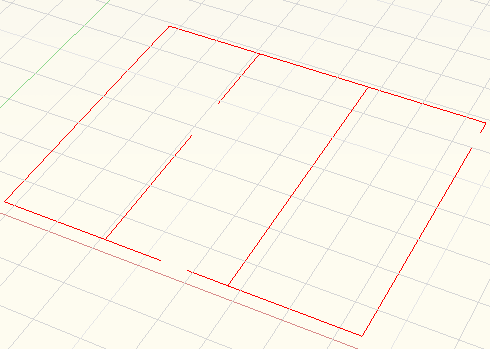
    1. Set the value of the DELOBJ system variable to 0 if you want to retain the 2D objects.
    2. To start the POLYSOLID command, choose Polygold from the Modeling toolbar. In 2009, choose Home tab> 3D Modeling panel> Polysolid.
    3. At the Specify start point or [Object/Height/Width/Justify] <Object>: prompt, type h and press Enter.
    4. At the Specify height <0′-4″>: prompt, type 8′ and press Enter to create 8′ high walls.
    5. At the Specify start point or [Object/Height/Width/Justify] <Object>: prompt, type w and press Enter.
    6. At the Specify width <0′-0 1/4″>: prompt, type 4 and press Enter to create 4″ wide walls.
    7. At the Specify start point or [Object/Height/Width/Justify] <Object>: prompt, press Enter to choose the Object option.
    8. At the Select object: prompt, select one of the lines or polylines that make up the 2D floor plan. (You can select only one object at a time.) AutoCAD creates the wall.
    9. Repeat the POLYSOLID command. It retains your settings, so just press Enter to use the Object option and select another line or polyline from the floor plan. Continue until you’re done.
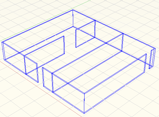
 

  • Set the value of the DELOBJ system variable to 0 if you want to retain the 2D objects.
  • To start the POLYSOLID command, choose Polygold fronm the Modeling toolbar. In 2009, choose Home tab> 3D Modeling panel> Polysolid.
  • At the Specify start point or [Object/Height/Width/Justify] <Object>: prompt, type h and press Enter.
  • At the Specify height <0′-4″>: prompt, type 8′ and press Enter to create 8′ high walls.
  • At the Specify start point or [Object/Height/Width/Justify] <Object>: prompt, type w and perss Enter.
  • At the Specify width <0′-0 1/4″>: prompt, type 4 and press Enter to create 4″ wide walls.
  • At the Specify start point or [Object/Height/Width/Justify] <Object>: prompt, press Enter to choose the Object option.
  • At the Select object: prompt, select one of the lines or polylines that make up the 2D floor plan. (You can select only one object at a time.) AutoCAD creates the wall.
  • Repeat the POLYSOLID command. It retains your settings, so just press Enter to use the Object option and select another line or polyline from the floor plan. Continue until you’re done.
 

Read more: http://www.ellenfinkelstein.com/autocadtips/AutoCAD_tips_walls_with_polysolids.html#ixzz15vFLRxUR

AutoCAD Tutorial: Create a mesh solid jar

This tutorial requires AutoCAD 2010 or later and shows how to create a mesh solid jar.

    1. Start a new drawing using acad3d.dwt.
    2. Switch to the 3D Modeling workspace by choosing it from the Workspace Switching pop-up menu on the right side of the status bar or next to the Quick Access toolbar at the upper-left corner of your screen.
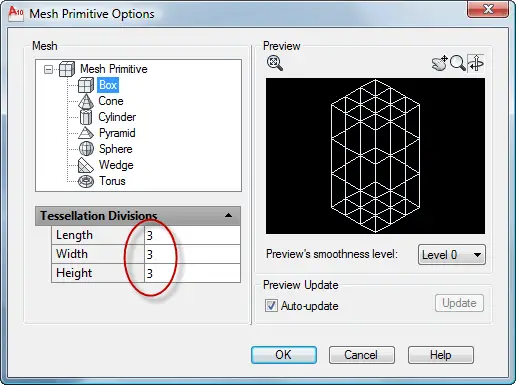
    3. Check that the tessellation divisions are the default 3 in each direction by clicking the Mesh Modeling tab, and then the dialog box launcher arrow at the right end of the Primitives panel title bar. Click OK.

    1. Still on the Mesh Modeling tab, in the Primitives panel, click Mesh Box. Follow the prompts:

Specify first corner or [Center]: Click anywhere on the XY plane.
Specify other corner or [Cube/Length]: c (for the Cube option)
Specify length: 2

    1. My mesh cube was rotated so I use the ROTATE command, selected the cube, specified a corner for the base point, and then used the Reference option. At the Specify the reference angle <0>: prompt, I picked one corner, and at the Specify second point: prompt, I picked the next corner. At the Specify the new angle or [Points] <0>: prompt, I pressed Enter to align the cube with the X axis.

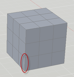
    1. In the Subobject panel, choose Edge from the Object Filter drop-down. Then choose Move Gizmo just to the right.
    2. Hold down the Ctrl key and click the bottom edge of any corner, circles in the above image. The Move Gizmo appears.
    3. Move your cursor until the XY plane (yellow) highlights, then push inward (into the cube). At the Specify stretch point or [Base point/Undo/eXit]: prompt, type .25.

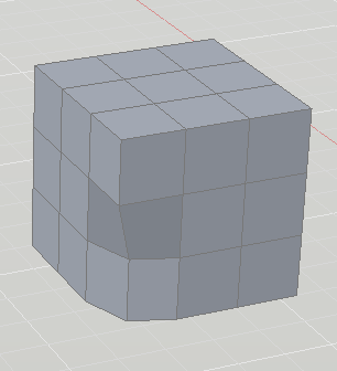
    1. Repeat for the other corners, being careful to deselect the previous edge first by pressing Esc. I hold Shift and my mouse’s wheel to transparently orbit, but you can use any method to change the viewpoint and access the other corners.

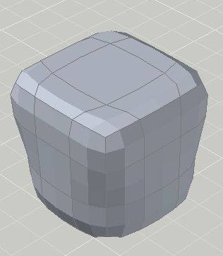
    1. In the Subobject panel, switch to the Face filter and the Scale Gizmo.
    2. Select the top center face. The Scale Gizmo appears. Select the XY plane (it becomes yellow — this isn’t always easy, but keep trying). At the Specify scale factor or [Base point/Undo/Reference/eXit]: prompt, enter 2.

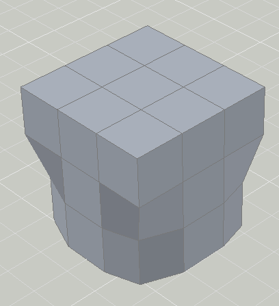
    1. On the Mesh Modeling tab, Mesh panel, click Smooth More. Select the mesh solid, and end selection.

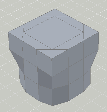
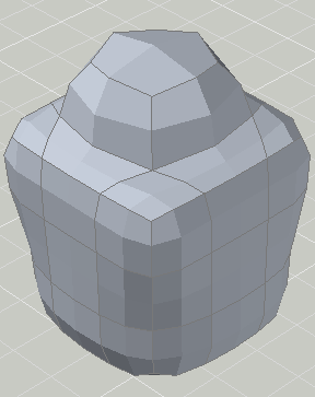
  1. To create the neck of the jar, choose Extrude Face from the Mesh Edit panel. Ctrl-select the top middle face and drag it upward. At the Specify height of extrusion or [Direction/Path/Taper angle] <2.0000>: prompt, enter .75.
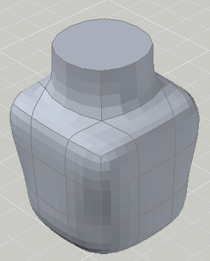
  2. To flatten the top, choose Add Crease from the Mesh panel. Ctrl-select the top, middle face and end selection. At the Specify crease value [Always] <Always>: prompt, press Enter.
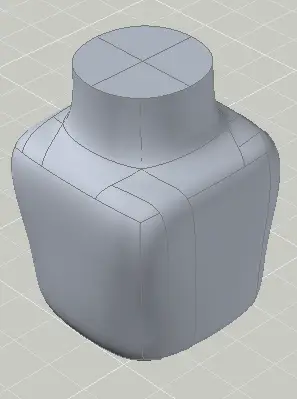
  3. On inspection, it seems like it could use more smoothing, so choose Smooth More again and select the model.

I wanted to shell out the inside, but every time I tried, AutoCAD stalled or told me “No solution for an edge.” You can try it at your own risk:

    1. On the Convert Mesh panel, choose Convert to Solid.

  1. On the Home tab, Solid Editing panel, click the bottom drop-down list and choose Shell. Select the solid and end selection.
  2. At the Remove faces or [Undo/Add/ALL]: prompt, select the top faces. I find this difficult to impossible.
  3. At the Enter the shell offset distance: prompt, enter .1.

I also tried making a copy, scaling it down, putting the smaller version inside the larger one, and using the SUBTRACT command. I wasn’t successful with that either. I’m open to suggestions. Leave a comment!


3D Tutorial: Draw a glass

This tutorial will create a drinking glass. I used the measurements of one that I had in my kitchen. I recommend using the 3D Drafting workspace

  1. Draw a circle with a radius of 1.25.autocad-tips-draw-a-glass-1
  2. On the View tab, click the Views drop-down and choose SE Isometric.
  3. Start the EXTRUDE command. Select the circle and end selection.
  4. Choose the Taper Angle option.
  5. Enter -5 for the taper angle. You use a negative number to taper outward.
  6. Enter 5.5 for the height of the extrusion

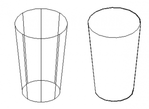
The results looks like a glass, as you see on the left. (I’ve changed the ISOLINES system variable to 8 to give it a nicer look.) But when you use the HIDE command on it, as you see on the right, you see that it’s a solid.

To create a glass, you use the Shell feature, which is part of the SOLIDEDIT command.

  1. On the Solid tab, in the Solid Editing panel, click the Shell button.autocad-tips-draw-a-glass-2
  2. Select your solid.
  3. At the Remove faces or [Undo/Add/ALL]: prompt, you need to remove the face that you don’t want to shell. For a glass, it’s the top face, because you want that face to remain open. In a view like the one above, you just click inside the top face of the solid.
  4. The prompt repeats; just press Enter.
  5. Enter 3/32 for the shell offset distance.
  6. Press Enter twice to exit the command. (If you find that you removed the wrong face, use the Shell option of the SOLIDEDIT command and try again.

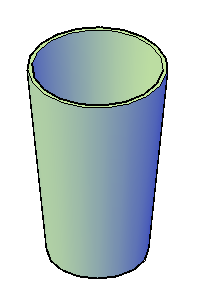
Here’s the result, with some shading.

Now, all you need is some water!

Work faster with AutoCAD keyboard shortcuts

Keyboard shortcuts can make your work go much faster. You can use the default keyboard shortcuts and create your own.

Here are the defaults that come with AutoCAD:

F1: Displays Help

F2: Toggles the Text Window

F3: Toggles OSNAP

F4: Toggles Tablet mode

F5: Toggles ISOPLANE

F6: Toggles Dynamic UCS

F7: Toggles GRID mode

F8: Toggles ORTHO mode

F9: Toggles SNAP mode

F10: Toggles Polar Tracking

F11: Toggles Object Snap Tracking

F12: Toggles Dynamic Input

CTRL+0: Toggles Clean Screen

CTRL+1: Toggles the Properties palette

CTRL+2: Toggles the DesignCenter palette

CTRL+3: Toggles the Tool Palettes Window

CTRL+4: Toggles the Sheet Set Manager

CTRL+6: Toggles the dbConnect Manager

CTRL+7: Toggles the Markup Set Manager

CTRL+8: Toggles the QuickCalc calculator palette

CTRL+9: Toggles the command window

CTRL+A: Selects all objects in the drawing

CTRL+SHIFT+A: Toggles Groups

CTRL+B: Toggles Snap mode

CTRL+C: Copies objects to Clipboard

CTRL+SHIFT+C: Copies objects to Clipboard with Base Point

CTRL+D: Toggles Dynamic UCS

CTRL+E: Cycles through isometric planes

CTRL+F: Toggles running object snaps

CTRL+G: Toggles the grid

CTRL+H: Toggles PICKSTYLE

CTRL+I: Toggles COORDS

CTRL+J; CTRL+M: Repeats the last command (pressing Enter does the same)

CTRL+L: Toggles Ortho mode

CTRL+N: Creates a new drawing

CTRL+O: Opens an existing drawing

CTRL+P: Prints/plots thecurrent drawing

CTRL+R: Cycles through layout viewports

CTRL+S: Saves the current drawing

CTRL+SHIFT+S: Opens the Save As dialog box

CTRL+T: Toggles TABLET mode

CTRL+V: Pastes data from the Clipboard

CTRL+SHIFT+V: Pastes data from the Clipboard as a Block

CTRL+X: Cuts objects to Clipboard

CTRL+Y: Cancels the preceding Undo action

CTRL+Z: Reverses the last action

CTRL+[; CTRL+\: Cancels the current command (pressing Esc does the same)

CTRL+PAGE UP: Moves to the next layout tab to the left of the current tab

CTRL+PAGE DOWN: Moves to the next layout tab to the right of the current tab

ALT+F11: Displays the Visual Basic Editor

ALT+F8: Displays the Macros dialog box

You can create your own keyboard shortcuts. See my tip, “Create a custom keyboard shortcut” for the detailed steps.

MTEXT-how to get a better clue of text size

When you start the MTEXT command, by default, you see the letters “abc” at the cursor to give you an idea of the size that the text will be. But those letters aren’t very helpful; it would be nice if you had more letters and more variety of sizes.

The MTJIGSTRING system variable (since AutoCAD 2004) creates some sample text when you start the MTEXT command. The idea is to help you gauge the size of the text before you create it, so you can change the height if you want. Lambertus Oosterveen sent me this line that you can put in your acaddoc.lsp or acad.lsp file:

(setvar “mtjigstring” (strcase (getvar “loginname”)))

It sets the text to your login name, making it all uppercase. I actually like having upper and lower case text because it helps me judge the size better, so I used the following simpler code:

(setvar “mtjigstring” (getvar “loginname”))

Here’s the result:

MTJIGSTRING has a maximum of 10 characters.