Text, also called single-line text, or Dtext, makes every line a separate object. It’s great for short annotation in a drawing. On the other hand, Mtext, also called multiline text, has more formatting options, and is better for larger amounts of text. Mtext is especially important if you need to create left and right margins and wrap the text between those margins.
Sometimes, you have single-line text that should be multiline text, or vice versa. Here are two simple ways to convert between the two types of text.
From text to Mtext
To convert from text to Mtext, use the Express Tools command TXT2MTXT. Choose Express> Text> Convert Text to Mtext.
At the Select objects: prompt, select the text objects that you want to convert. If you press Enter instead, you get the Text to MText Options dialog box. Set the options as you want and press OK. By default, the command sorts from the top object downward, and tries to word wrap the Mtext that it creates.
One nice feature of the command is that if you select text objects first, the command executes without further input — very efficient! Another efficient feature is that the command does a true conversion; your old text objects are gone.
## Dynamic block is another great productivity tip to master. Sign up below to get your Free tutorial on creating a complete dynamic block, including a drawing to practice on. You’ll make a movable chair, resizable desk, and more.
From Mtext to text
The easiest way that I found to convert Mtext to text is simply to copy and paste. Double-click the Mtext to open the Mtext editor. Select the text and copy to the clipboard. Then close the editor.
Start the DTEXT or TEXT command. Specify the start point, height and rotation angle as usual. You’ll then see a small box and cursor. Paste from the clipboard and press Enter to end the command. You’ll then need to delete your Mtext object.
Jimmy Bergmark reminded me that you can simply explode the Mtext. The difference is that you’ll keep the line wrapping. It all depends on which result you want. A bonus is that you don’t have to delete the original object.
If you insert titleblock text for your drawings, you know that keeping that text updated and accurate can be a chore. Also, many people place drawing numbers and names in more than one place in a drawing, requiring extra work.
You can use fields to automate the insertion of titleblock text – or any other annotation in a drawing. Especially if you use the text over and over again, you can save time and improve accuracy. Examples are the current date, the drafter’s initials, the company name and address, and so on.
In this tutorial, I assume that you’re using MText for your titleblock text, but you can use the same technique with block attribute text.
Follow these steps:
You use the Drawing Properties feature to create custom properties. Choose the Application button> Drawing Utilities> Drawing Properties or choose File>Drawing Properties to open the Drawing Properties dialog box.
Click the Summary tab. If you can use any of these properties, start here. For example, you can use the Title field for the drawing name.
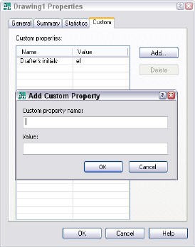
To add a custom field, c lick the Custom tab. Use a custom field for content that cannot use one of the fields that come with AutoCAD.
Click the Add button. In the Add Custom Property dialog box, enter a field name and value and click OK.
Repeat Step 4 for all of your custom fields.
Click OK to close the Drawing Properties dialog box.
To insert fields, start the MTEXT command and define the bounding box (or use the ATTDEF command to create an attribute definition).
In the Text Editor (or Value or Default text box of the Attribute Definition dialog box), right-click and choose Insert>Field. You can do the same in a table.
To find your custom fields most easily, choose Document from the Field Categories drop-down list. You’ll see all your custom fields listed.
Choose the field you want, choose a format, and click OK.
Repeat Steps 7-10 for all your custom fields.
To use any of the fields that come with AutoCAD, again choose Insert>Field, choose a different category, field, and format.
Check out this free dynamic block tutorial
Plus get free tips in our AutoCAD Tips Newsletter!
Get a free tutorial on creating a complete dynamic block, including a drawing to practice on. You'll make a movable chair, resizable desk, and more. PLUS, the highly-acclaimed AutoCAD Tips Newsletter will keep your skills up to date!
Note: The CreateDate field creates an unchanging date field, based on today’s date. The Date field creates a date field that always changes to display today’s date.
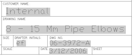
The gray background tells you it’s a field; the background doesn’t print.
You can save your custom fields in a template and have them available for any drawings based on that template.
AutoCAD comes with some very interesting and useful fields. Browse through the list to see if some might be useful for you. For example, choose Insert>Field, choose the Objects field category, choose the Object field, and click the Select Object button to select an object in your drawing. Now you’ll see a list of properties that you can choose from. You can use this to create labels that display properties about your objects, such as the area of a circle or the coordinates (position) of any object.
When you save and close a drawing, AutoCAD remembers the last displayed view and opens it to that view. That’s convenient for continuing where you left off.
But what if other people are also working on the drawing and they change the display? Or if you know you want to go to another part of the drawing?
You can open a drawing to any named view, controlling what you see when you open the drawing. First you save a named view. Here’s how:
Display the view that you want to be able to display.
Choose View > Named Views (in AutoCAD Classic workspace) or View tab> Viewports panel> Named (in 2D Drafting & Annotation workspace in AutoCAD 2009) .
Click New.
Name your view and click OK twice to return to your drawing.
Save and exit your drawing.
When you are ready to open the drawing next time, here’s what you do to ensure that you see the view you want:
Click Open to display the Select File dialog box.
Check the Select Initial View check box, as you see here.
In the Select Initial View dialog box, choose your view and click OK.
You can create dynamic blocks that you can easily flip after you insert them. This is great for doors which may open from the left or right, or open inward or outward. Dynamic blocks were introduced in AutoCAD 2006.
Follow these steps to create a door that flips both ways:
Start with a door block, like this one. You might want to insert it into a new drawing. You don’t need to explode it; when you open it in the Block Editor, you’ll have access to all the individual components, as if you had exploded it. That’s one of the great features of dynamic blocks; you can work with complex blocks that contain many components and individually program each component.
Choose Block Editor from the Standard toolbar (the BEDIT command). Here’s what you see.
Note that the Block Editor has its own toolbar. It also has its own UCS icon. This is very important, because 0,0 in the Block Editor will be the insertion point of the block. When you open the block in the Block Editor, its insertion point will be at 0,0 in the Block Editor, like this:
The first flip action we’ll create will be like mirroring with a vertical mirror line; it will flip the door to the left or right. Unflipped, the door will be as you see it here, which means it opens from the right to the left. Flipped, the door will open from the left to the right.
Click the Parameters tab of the Block Authoriing Palettes window and choose Flip Parameter. At the Specify base point of reflection line or [Name/Label/Description/Palette]: prompt, choose the Label option. This option lets you customize the label. It’s important to change it, because we’ll have two flip parameters when we’re done. Enter Flip Left/Right.
You can also customize the names for both states (which appear in the Properties palette). so the next thing you see is this prompt:
Specify values for items in the flip property dropdown control:
Enter flip property value for an unflipped state <Not flipped>:
Enter flip property value for a flipped state <Flipped>:
You can leave the defaults (Not flipped and Flipped), but instead, enter Opens at right for the unflipped state and enter Opens at left for the flipped state. Later, when you select the block, you can see which state you have in the Properties palette.
You can change these values at any time by selecting the parameter and using the Properties palette.
Now the original prompt returns. Specify base point of reflection line or [Name/Label/Description/Palette]: Specify the midpoint of the bottom horizontal line of the door. Specify endpoint of reflection line: Specify any point 90° above the midpoint, to make a vertical flipping line. Specify label location: Place the label above the door.
Notice the exclamation point. That tells you that you haven’t completed the process of flipping the door. That’s because most parameters also require a corresponding action.
Click the Actions tab of the Block Authoring Palettes window and choose Flip Action. A Flip action always goes with a Flip parameter.
At the Select parameter: prompt, select the parameter you just added.
At the Select objects: prompt, select all the objects of the door. In this situation, you can include the parameter, too.
At the Specify action location: prompt, place the action, usually near the parameter label. It doesn’t show in your drawing, so it’s just for your convenience when editing the block in the Block Editor.
You can change the action’s name. Select it and change the Action Name value in the Property palette to Flip left/right action. I find it helpful to distinguish the parameter label from the action name. Our door now looks like this in the Block Editor.
Click Save Block Definition on the Editor’s toolbar (the 2nd button from the left). To try it out, click Close Block Editor. If you already have inserted an instance of the block in the drawing, you get a message about it. Click Yes.
To test the block, choose Insert Block from the Draw toolbar and choose the block. In the Insert dialog box, you should see that yellow lightning icon in the preview box, to show that it’s a dynamic block. Make sure that only the Insertion Point Specify On-Screen check box is checked and click OK.
Specify the insertion point in your drawing to insert the block. To flip it, select it and you’ll see the turquoise flip grip on the block. Click the grip to flip the door. Click it again to flip it back.
When you’re satisfied, open the Block Editor again, choose the block and click OK. Now you need to add the flip for the other direction.
Again, click the Parameters tab and choose Flip Parameter. At the Specify base point of reflection line or [Name/Label/Description/Palette]: prompt, pick the midpoint of the right side of the door — the short side. You may have to zoom in to do this. At the Specify endpoint of reflection line: prompt, move the cursor to the left and pick any point 180° from the first point (creating a horizontal mirror line). At the Specify label location: prompt, pick a point to the right of the door, or perhaps just beneath it.
Tip: When you zoom in and out, sometimes the size of the labels gets out of synch. Click the Update Parameter and Action Text Sizebutton on the Editor’s toolbar.
Select the parameter. In the Properties palette, change the label to Flip in/out.
Click the Actions tab and choose Flip Action. At the prompt, select the parameter you just created.
At the prompt to select objects, select the door. Not only can you select this action’s parameter, but you can select everything else (which makes it easy).
If you want, change the name of the action in the Properties palette. I changed it to Flip in/out action. Here’s the final dynamic block in the Block Editor.
Click Save Block Definition and click Close Block Editor. If you get the notice about an existing block reference existing in the drawing, click Yes.
Here you can see the block at work. It flips both ways!
Some coordinates are easy to find. For example, to find the endpoint of a line, you just use the Endpoint object snap.
But others are more elusive.
For example, recently someone asked me, “I would like to ask if there is a simple way to select a center of a rectangle.”
My answer was: If you press Shift and right-click, you’ll get the OSNAP menu. Choose Mid Between 2 Points, and choose two diagonal corners.
Finding coordinates is a very common task, so here are some other tips for specifying hard-to-find coordinates.
Polar coordinates
To find a point at a specific angle, use polar coordinates, in the format distance<angle. So, to draw a line that is 3.5 units at a 15°, enter 3.5<15.
Apparent Intersection OSNAP
The Apparent Intersection object snap finds an intersection that would be created if you extended two objects until they met. It’s very simple to use. You start a command, such as the LINE command, specify the OSNAP (you can type app), specify a first point, such as an Endpoint, then hover over the second point. You’ll see an X at the apparent intersection. Just click to lock in the coordinate.
Watch the video.
Extension OSNAP
The Extension object snap extends lines and arcs in the same direction, past their endpoints. Look for the Extension tooltip; at the same time you’ll see a temporary extension path.
Watch the video.
Object snap tracking
Object snap tracking lets you specify a point based on object snaps of existing objects. When you’re looking for the intersection of two existing endpoints, it works similarly to the Apparent Intersection OSNAP. But it has more uses that that. For example:
Your want the endpoint of a line you’re drawing to be vertical to the endpoint of an existing line.
You want to center a circle inside a rectangle
You want to start a line where two existing lines would intersect if they extended (you can do this with the Apparent Intersection object snap, too)
Note that you can use object snap tracking with polar snapping, so the angles don’t have to be orthogonal.
Follow these steps:
Turn on at least one running object snap. To do so, right-click the Object Snap (OSNAP) button on the status bar and choose an object snap, or choose Settings first (depending on your version).
Click the Object Snap Tracking button on the status bar (which is different from the Object Snap button). to turn on this feature.
Start a drawing command that requires you to specify a point.
Hover the cursor over an object snap, to acquire that point. You see a small plus sign at the object snap point.
If necessary, acquire a second point.
Move the cursor toward the coordinate you want to locate until you see one or two temporary, dotted alignment paths. You’ll also see one or two tooltips and an X.
Click to specify the point. Then continue the command you started..
Here, I started the CIRCLE command and acquired the midpoints of the two sides of the rectangle to find its center. This specifies the center of the circle at the center of the rectangle.
Here’s the result:
Temporary tracking
You can also use temporary tracking to accomplish the same result, as long as the angles are orthogonal. Follow these steps:
Turn on at least one running object snap. To do so, right-click the Object Snap (OSNAP) button on the status bar and choose an object snap, or choose Settings first (depending on your version).
Start a drawing command that requires you to specify a point.
Type tk and press Enter.
At the First Tracking point: prompt, specify an object snap by clicking it. It must be horizontal or vertical to the final point that you want to specify.
Move the cursor horizontally or vertically toward the desired coordinate. You see a solid, temporary rubber-band line.
At the Next point: prompt, move the cursor from the rubber-band line to the second object snap, and click.
Press Enter to end tracking and continue the command.
Point filters
Point filters are the original way to specify coordinates that aren’t on an object, based on object snaps of existing objects. Most people use object snap tracking now, but they can still be useful, especially in 3D work. You build an X,Y (or X,Y,Z) coordinate by using the X coordinate of one object snap, the Y of another, and perhaps a Z of another.
Follow these steps:
Start a drawing command that requires you to specify a point.
Type .x or .y and press Enter. (You can also Shift + right-click to choose a point filter from the object snap menu.) Let’s say I start by typing .x.
At the of (need YZ): prompt, use an object snap to specify the x coordinate of the desired coordinate. To continue the example of drawing a circle centered inside a rectangle, you would specify the midpoint one of the rectangle’s horizontal lines, because the x coordinate of the circle’s center should be the same as the x coordinate of the horizontal line’s midpoint.
Now, simply specify the object snap on an object to locate the y coordinate. In this example, specify the midpoint of one of the rectangle’s vertical lines.
AutoCAD locates the coordinate and you can continue the command.
From
From is a feature that lets you find coordinates off objects by specify the offset from an object snap. You can specify that offset as the x,y distance or polar coordinate notation.
Follow these steps:
Start a drawing command that requires you to specify a point.
Type from and press Enter. (You can also Shift + right-click and click From on the object snap menu.)
At the Base point: prompt, specify the base point with an object snap.
At the Offset: prompt, enter @ and relative x,y or polar coordinates. Note: You must use @ even if you are using a default of relative coordinates.
Continue the command.
Do you have other ways of locating hard-to-find coordinates?
Tiled viewports let you divide up the drawing area into tiles and display different parts of your drawing in each. The great thing about tiled viewports is that you can draw from one viewport to another without missing a beat, making them great for large drawings where you need to alternate between working in detail in a small area and working in a larger area. In fact, it’s common to use one viewport for a view of the entire viewport, and others for zoomed in details.
You can set up a wide variety of configurations of tiled viewports, and set the view however you want in each one, using standard zooming and panning. But no matter how you set them up, they always take up the entire drawing area, unlike floating viewports.
Note: Floating viewports are for laying out a drawing in paper space for plotting. Tiled viewports are for drawing and editing.
Only one tiled viewport can be active at a time. The crosshairs appears only in the active viewport. Just click inside a viewport to make it active. Then you can draw or edit there, in the same way you usually do in model space, when you only have one viewport, which is the default.
Create tiled viewports
To choose from preset tiled viewport configurations, choose View> Viewports> New Viewports. In AutoCAD 2009 and 2010, go to View tab> Viewports panel> New. This opens the Viewports dialog box.
Choose one of the options to see its preview. Note that at the bottom, you can make the following adjustments:
* Apply to: You can use the default Display option to apply the configuration to the entire drawing area. Alternatively, you can choose Current Viewport from the drop-down list to divide up an existing viewport. In this way, you can create customized configurations. * Setup: You can choose 2D or 3D. If you choose 3D, AutoCAD creates standard orthogonal views of your model for you. * Change view to: You can choose named views that you’ve saved from this drop-down list. * Visual Style: For 3D drawings, you can choose a visual style.
Use tiled viewports
Once you have your viewports, click inside each one and zoom and pan until you have the view that you want. You work inside a viewport in the same way you would without them. Think of the usual way you work as a single tiled viewport.
Let’s say that you need to draw a line from the far left of your drawing to the far right. With the configuration shown above, you can zoom in to the left side of your drawing in the lower-left viewport, and zoom in to the right side of your drawing in the lower-right viewport. Then follow these steps:
1. Click in the lower-left viewport and start the LINE command. 2. Specify the start point as needed. 3. At the Specify next point or [Undo]: prompt, click the top viewport and move the cursor to the approximate location of the endpoint at the right side of your drawing. 4. Click the lower-right viewport. Now you see the endpoint of the line. Specify the endpoint and press Enter to end the LINE command.
You can use a similar technique for editing as well.
Save and restore viewport configurations
If you have a custom configuration that you like, you can save it. Choose View> Viewports> New (View tab> Viewports panel> New in 2009/2010), which opens the Viewports dialog box with the Named Viewports tab on top. The current configuration is highlighted, named Active Model Configuration. Enter a name in the New Name text box. The name can be up to 255 characters and can include spaces. Click OK.
Tp restore a saved configuration, choose View> Viewports> Named Viewports (View tab> Viewports panel> Named (Viewports) in 2009/2010). This opens the same Viewports dialog box, but with the Named Viewports tab on top. Choose the configuration you saved, and click OK.
Tip: Did you know that you can used saved tiled viewport configurations to make configurations of floating viewports? You use the same Viewports dialog box to create floating viewports on a layout and you’ll find your saved viewport configurations on the Named Viewports tab, ready to use in paper space.
Remove tiled viewports
You can remove tiled viewports in two ways:
* Join two viewports: Choose View> Viewports> Join (View tab> Viewports panel> Join (Viewports) in 2009 and 2010). At the Select dominant viewport : prompt, click inside the viewport you want to keep (or press Enter to keep the active viewport). Then, at the Select viewport to join: prompt, click inside an adjacent viewport. The resulting view is the same as the dominant viewport. * Return to one viewport: Choose View> Viewports> 1 Viewport. (In 2009 and 2010, View tab> Viewports panel> Select a Viewport Configuration/Viewport Configuations drop-down list> Single.)
Related tips:
* Display a named view in a viewport * Zoom to objects
Ever need to place an object evenly along a polyline or spline? For example, you may want to divide a plat into equal sections or 40′ sections. For whatever reason, you can do this easily using the DIVIDE or MEASURE command.
These commands are especially useful when your object is a curvy polyline or spline for which the COPY and ARRAY commands are useless. (Update: Starting with AutoCAD 2012, you can array along a path, including a polyline or spline.)
By default, these commands place point objects, but they can also place a block of your choice. Even better, you can rotate the block along the polyline or spline if you want.
If you want to place a point object, first set a point style that you can see. If you want to place a block, create the block. If you use a block, be sure that the block’s insertion point is at the center of the block, so that the block will be nicely centered on your polyline or spline.
The DIVIDE command places a point object or block evenly along your object, dividing it into equal portions (but it doesn’t actually break the object or affect it in any way.) To use the DIVIDE command to divide a polyline or spline (or even a line), follow these steps:
1. Start the DIVIDE command. 2. At the Select object to divide: prompt, chosoe the object along which you want to place the points or blocks. 3. At the Enter the number of segments or [Block]: prompt, enter the number of segments you want to create, or enter b to use the Block option. 4. If you use the Block option, at the Enter name of block to insert: prompt, type the block’s name. At the Align block with object? [Yes/No] : prompt, enter y or n. Then the Enter the number of segments: prompt returns. Specify a number.
AutoCAD places the points or blocks evenly spaced along your object..
The MEASURE command is similar to the DIVIDE command, but places the points or blocks at a spacing your specify. Here’s how to use it:
1. Start the MEASURE command. 2. At the Select object to measure: prompt, select the object along which you want to place the points or blocks. 3. At the Specify length of segment or [Block]: prompt, specify the distance between points or enter b to use the Block option. 4. If you use the Block option, at the Enter name of block to insert: prompt, type the block’s name. At the Align block with object? [Yes/No] : prompt, enter y or n. Then the Specify length of segment: prompt returns. Specify a spacing.
AutoCAD places the points or blocks spaced at the distance you specified..
How do you use the MEASURE or DIVIDE commands? Leave a comment!
If you found this post useful, please use the social media buttons below to share it with others.
When you place a hatch inside a closed area, by default, the pattern starts at the origin of the drawing, which is usually 0,0 of the current User Coordinate System (UCS). Since your closed area probably doesn’t start at 0,0, the hatched area starts somewhere in the middle of the pattern.
For simple hatches, such as diagonal lines, that doesn’t make any difference. But for some hatch patterns, such as bricks, the result may not look very good.
You can specify the origin of the hatch pattern to get a better-looking result. Follow these steps:
Create the enclosed area and start the BHATCH/HATCH command to open the Hatch and Gradient dialog box or display the Hatch Creation tab.
In the Type and Pattern section or Pattern panel, choose the hatch pattern you want.
You can refine the hatch in the Angle and Scale section or the Options panel (depending on the release you’re using).
In the Hatch Origin section, choose the Specified Origin option. If you have the Hatch Creation tab, click the Origin panel’s drop-down arrow.
For the dialog box, if you want the hatch to start at one of the corners of the enclosed area (bottom-left, top-left, etc) or the center, check the Default to Boundary Extents check box and choose one of the options from the drop-down list. If you want to pick a specific location, click the Click to Set New Origin button to return to the drawing, where you can pick any point that you want.
For the Hatch Creation tab, choose one of the options from the buttons.
To store your selections as the default, check the Store as Default Origin check box/button.
Click Add Pick Points or Add Select Objects/Select to specify where to place the hatch.
Here’s the new result, using the Default to Boundary Extents check box with the Bottom-Left option:
This tutorial is unusual, because you don’t need AutoCAD to do it.
You draw full size in AutoCAD. But before long, you may need to set the scale of text, dimensions, and other objects that need to be the right size after you plot on a sheet of paper. In a large drawing, such as a drawing of a house, you obviously need to scale down to fit it on a sheet of paper. For small objects, you might scale up.
You can add text and dimensions in paper space and avoid scaling. You can also use annotative text and dimensions, but you still need to choose a scale.
Let’s say you have a drawing of a house. The drawing is 175 feet wide by 120 feet high. Some typical scales for an architectural drawing of a house in the United States are 1/4″=1′ and 1/8″=1′.
Follow these steps:
Calculate the plotted size of the width at 1/4″=1′. 175′ x 1/4 = 43-1/4″.
Calculate the plotted size of the height at the same scale. 120′ x 1/4 = 30″.
Test this size on a size D sheet (34″x22″). It’s too small. Test it on a size E sheet (44″x34″). It would just fit, but allowing for a title block and margin would make it too tight.
Recalculate the width at 1/8″=1′. 175′ x 1/8 = 21-7/8″.
Recalculate the height at 1/8″=1′. 120′ x 1/8 = 15″.
A size C sheet (22″x17″) is close but you might have problems with the margins. If you can move some objects in the drawing to make it slightly narrower, you’ll do fine. Otherwise, you’ll need a size D sheet.
Sometimes, you need the scale factor, which is just how many times bigger the full size is compared to the plotted size. For a 1/8″=1′ scale. multiply both sides of the equation by 8 to get 1″=8′. Then convert to inches. 8″ x 12 = 96.
Important: While we don't collect cookies, some of our 3rd-party services (such as PayPal and WordPress) do, to give you a safer and better browsing experience. Read about how we use cookies and keep your personal information secure by reading our Privacy Policy here.


")


