For consistency, instead of simply picking a location for a dimension, you can specify its distance from the object. At the Specify dimension line location prompt, you can enter one of the following to place the dimension .5 units above the object (for example):
@0,.5
@.5<90
Thanks to Adeel Abdullah of Amec Earth & Environmental in Alberta, Canada for the idea for this tip and specifically the second (polar) option.
The Mtext Editor has three options that many people miss. In the Mtext window, select the text you’ve entered and right- click inside the text area. Choose one of the options:
Change Case to change the text to all uppercase or all lowercase.
Choose Remove Formatting to return all text to Txt font and remove bold, italic and other formatting.
There are several ways you can let AutoCAD do some quick arithmetic for you when you need a distance. Let’s say you’re drawing a line and you want to use direct distance entry to specify the length. What you know is that that line should be 4.372 plus 3.925. Of course, you could use a hand calculator or (gasp!) take out a pencil and paper and do the math.
Use an AutoLISP expression
Tony Dakin suggested the following method, which uses an AutoLISP expression. At the Specify next point or [Undo]: prompt, enter the following:
(+ 4.372 3.925)
Start with a left parenthesis.
Next comes the operator, such as. + – * or /.
Add a space
Add the first number
Another space
Add the second number
Close the parentheses.
Use the CAL command
There’s another way: you can use the old CAL command. Here’s how:
At the Specify next point or [Undo]: prompt, enter ‘cal and press Enter.
At the >>>> Expression: prompt, simply enter 4.372 + 3.925 and press Enter.
Enter math expressions in dialog boxtext boxes and the Properties palette
Did you know that you can enter expressions in dialog boxes and the Properties palette? Just type the expression, such as 4.372+3.925 and press Alt-Enter (don’t forget to press the Alt key!) You may have to press Enter to complete the change. For example, you can use this method to change the radius of a circle in the Properties palette.
For this to work, the CALCINPUT system variable must be set at 1, which is the default setting.
Some people (mostly architectural types) like their fractions like this:
Others (mostly mechanical types) like their fractions like this:
These are called stacked fractions. And some people like their fractions unstacked. Of course, unstacked fractions are easy; it’s the stacked ones that require a bit of knowledge.
For Multiline text, you can format fractions as you type, and also set the format of individual fractions if you need to change the way your fractions look.
To create stacked fractions as you type, open the Multiline Text Editor and follow these steps:
Type the numerator.
Type the character that defines the fraction format you want:
Type a slash (/) to create a fraction separated by a horizontal line.
Type a pound symbol (#) to create a fraction separated by a diagonal line.
Type a carat (^) to create a tolerance stack, which is like a fraction separated by a horizontal line except that there is no horizontal line.
Type the denominator.
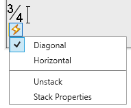
Type a space (or other nonnumeric character). A lightning symbol appears.
Click the lightning symbol that appears to display more options, as you see here. Use this shortcut menu makes it easy to change the type of fraction.
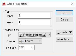
Click Stack Properties in the menu to open the Stack Properties dialog box, which looks like this. (You can also select a fraction, right-click, and choose Stack Properties.)
Here you can choose the style of fraction, specify the position relative to the text baseline, and set the text size for the numerator and denominator. You can use the Defaults button to either restore original defaults or use the settings that you specified in the dialog box as the defaults. Click OK when you’re done.
The Style list has a 4th type of fraction, Decimal, which is like a tolerance fraction but aligns the decimal point of the selected numerator and denominator.
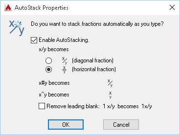
Click AutoStack to open the AutoStack dialog box, shown here.
You can choose in the AutoStack Properties dialog box how x/y should stack. The purpose of this dialog box is to make stacking fractions easy each time you do it. You can also remove the leading blank before a mixed fraction. Click OK when you’re done.
Ted Harris e-mailed me an AutoLISP routine that he uses to follow a linear dimension with a continued dimension. He notes, “one rarely enters one Dim, at least in a production environment.” I’ve updated his solution for recent versions of AutoCAD.
Add this to your acad.lsp file or create a separate LSP file and load it. When you’re ready to dimension, enter dlc and press Enter. (DLC stands for dimension linear continued.) The command starts the DIMLINEAR command and pauses for you to specify the start and end point and place the dimension line. Immediately afterward, the DIMCONTINUE command starts and you can continue to dimension.
Normally, dimensions are associative, meaning that they change when you edit objects to which they’re attached.
Drawings created in releases 2000 and earlier are not associative. Sometimes, you’ll get a drawing that was created a long time ago and realize that the dimensions aren’t associative.
To make them associative, type dimassoc (a system variable) on the command line and look at its value. If it isn’t 2, type 2 and press Enter. However, this just affects new dimensions.
To associate existing dimensions from an old drawing to its objects, use the DIMREASSOCIATE command. On occasion, you need to use this command because dimensions have become disassociated.
Type dimreassociate on the command line.
At the Select objects: prompt, select the dimensions and press Enter to end selection.
At the next prompt, follow the instructions to specify the point on the object to connect to the dimension. The prompt varies according to the type of dimensions you select. For example, if you selected a linear dimension, the prompt reads: Specify first extension line origin or [Select object] <next>:. This is very similar to the prompt you get when creating a linear dimension in the first place. You see an X marker (shown at the arrow in the figure) that corresponds to the part of the dimension for which you need to specify the point.
The next prompt completes the process. For example, for a linear dimension, the prompt is Specify second extension line origin <next>:. The X marker moves to the second end of the dimension.
The command prompts you through all of the dimensions that you selected.
AutoCAD 2005 and earlier doesn’t have a way to dimension arc length, but Leonid Nemirovsky has come up with an AutoLISP routine that dimensions arc lengths very nicely. You can download it here.
Here’s the result:
Leonid has many, many more AutoLISP routines on his site, Better Than Nothing AutoLISP.
AutoCAD 2006 and later has this feature. Use the DIMARC command.
The new fields in AutoCAD 2005 make it easy to add text that updates automatically. For example, you can put today’s date, the sheet number, and Drawn By initials in your title block. However, if you don’t have 2005 but have Express Tools (they come with 2004 and you can purchase them for $149 if you have 2000, 2000i, or 2002), you can create fields using the Express Tools RTEXT command and some simple DIESEL expressions. Don’t let the DIESEL scare you; these expressions are easy to use. Here’s how:
Start the RTEXT command or choose Express>Text>Remote Text. (RTEXT is often used to display text coming from an outside, or remote, file.)
Choose the DIESEL option.
In the Edit Rtext dialog box, enter one of the following expressions:
Drawing file: $(getvar, “dwgname”)
Drawing name with path: $(getvar, “dwgprefix”)$(getvar, “dwgname”)
Tab (model or layout): $(getvar, ctab)
Date: $(EDTIME,0, M/DD/YY)
Drawing property: $(getprop, property name) The standard property names are Title, Subject, Author, Comments, Keywords, LastSavedBy, and Revno. You can even use a custom property, with the format $(getprop, %custompropertyname). For example, if you have a custom property named Customer, you would use $(getprop, %customer).
Click OK and follow the prompts to place the text.
Tip: To add the drawing name without the “.dwg” use the following expression:
Thanks to Curtis Waguespack for this tip and the idea for this entire topic.
As you may have guessed, the “getvar” part of the code gets the value of system variables. You may find other system variables that you would like to display in your title blocks. Experiment!
Do you keep supporting notes for your AutoCAD drawings on a notepad next to your computer? Do you sometimes need to jot down tasks to complete, explanations of objects, or locations of supporting data?
Instead of using pen and paper, you can insert this information into your drawing and have easy access to it whenever you need it. Furthermore, you can easily change and update your notes.
Start by creating a new layer for your notes. Then insert a table and enter the text. When you get ready to plot or send the drawing, just freeze its layer. It won’t plot and it won’t be visible to others. Or, as Doug Hess notes, just change the layer’s state to Not Plottable in the Layer Properties Manager.
When the drawing is finalized, you can delete the notes and remove the layer if you want.
Another way to keep electronic notes is to use a separate document, such as a .txt document that you open in Notepad, and hyperlink to it from your drawing.
The original idea for this tip came from Dieter Schlaepfer at Autodesk.
Dimension styles are a great way to organize and manage your dimensions. Usually, you use the DIMSTYLE command (Dimension>Dimension Style or Annotate tab> Dimensions> Dimension Style).
But you can quickly create a new dimension style from an existing dimension with the Properties palette. Select a dimension and display the Properties palette.
All the properties of the dimension are listed there. Make any changes you want.
After you’re done, right-click in the drawing area and choose Dim Style>Save as New Style from the shortcut menu.
The New Dimension Style dialog box opens so that you can give the dimension style a name. Then click OK.
Important: While we don't collect cookies, some of our 3rd-party services (such as PayPal and WordPress) do, to give you a safer and better browsing experience. Read about how we use cookies and keep your personal information secure by reading our Privacy Policy here.