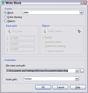
If you want to writeblock a block (use the WBLOCK command to save the block as a separate drawing file), normally, you’d start the WBLOCK command first. But then you have to choose the Block option in the Write Block dialog box and use the drop-down list to choose the block you want to write.
Instead, select the block first. When you start the command, you’ll find the Block option selected and the block already active in the drop-down list.
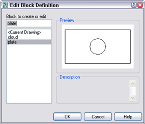
In the same way, if you want to edit the block in the Block Editor, select it first. Then click the Block Edit button (the BEDIT command). The block will already be selelcted in the Edit Block Definition dialog box, so all you need to do is click OK.
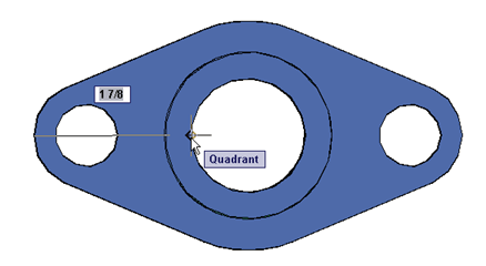
AutoCAD displays tooltips for object snaps, polar tracking, and dynamic tooltip. The object snap and dynamic tooltips can get in each others’ way. The Quadrant tooltip, as you move the cursor slightly, will alternate between saying Quadrant and Specify next point or ↓.
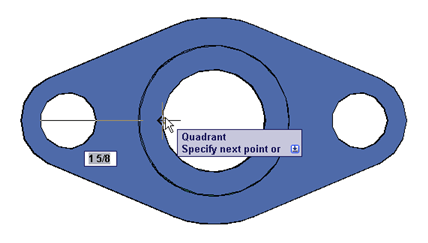
By changing the TOOLTIPMERGE system variable to 1, you can combine the tooltips and see them together.
Sometimes the tooltip hinders you from seeing part of the drawing. To temporarily turn off dynamic input, along with its tooltip, press and hold F12. When you release F12, dynamic input comes back. This can be smoother than clicking the DYN button off and on, on the status bar.
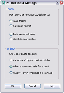
You can control whether you see the tooltip when a prompt appears for a point (the default), only when you start typing a point, or always. Right-click the DYN button, and choose Settings, Then click the Settings button in the Pointer Input section.
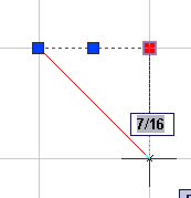
When you grip edit objects, by default, you see one dynamic input tooltip, representing the change in length, of a line for example.
The line was 1 unit and will now be 1-7/16 units, so the change is 7/16 units.
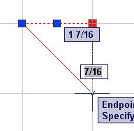
But you have many other tooltip options. For example, you can show both the change in length and the resulting dimension.
The problem with this is that it can be hard to tell which tooltip is giving you which information.
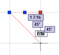
Finally, you can show 3 other tooltips:
Absolute angle
Angle change
Arc Radius
Here’s what happens when you show all of the tips!
OK, so that’s a little overwhelming. But here’s how to control what you see:
Right-click the DYN button and choose Settings.
In the Dimension Input section of the Dynamic Input tab of the Drafting Settings dialog box, choose Settings.
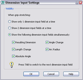
In the Dynamic Input settings dialog box, choose one of the following:
Show Two Input Fields at a Time
Show the Following Dimension Input Fields Simultaneously, and check the fields that you want to see
When you’re drawing a line at an unusual angle, you may want to see how the angle looks. After you specify the first point, you can type the < (angle) symbol and then the angle you want to try. For example, <10.
This locks the next segment to that angle while you enter the length. This is called a polar override angle and you see the following on the command line:
Angle Override: 10
Now you can see what the angle looks like and move the cursor to various lengths to see where the line at that angle will go. To complete the segment, type the length and press Enter.
When you draw an arc, the specifications that you provide may define two, rather than one arc — one minor (less than 180 degrees) and one major. The ARC command always draws the minor arc by default, in the counterclockwise direction.
For example, if you specify the Start, End, and Radius options, the center can be in two places, which can mean two possible arcs, one minor and one major, as you see here.
Polar tracking is a great way to simplify the creation of lines, because once you find the right angle, all you need to do is to enter the length. You should try to banish the entry of coordinates in the x,y format as much as possible, because it’s so slow.
You can customize the angles that polar tracking uses to suit any need. Right-click the POLAR button on the status bar and choose Settings. On the Polar Tracking tab of the Drafting Settings dialog box, you can change the increment angle, which is 90 degrees by default. The increment angle means that polar tracking will activate at that angle and every multiple of that angle. You’ll also get a bonus of polar tracking at 0 degrees.
For example, you can set the increment angle to 15, which means you’ll have polar tracking at 0, 15, 30, 45, 60, 75, 90, 105, 120, 135, 150, 165, 180, 195, 210, 225, 240, 255, 270, 285, 300, 315, 330, 345. Is that enough angles for you?
To set the increment angle, choose one of the angles from the Increment Angle drop-down list or simply type in your own angle.
If that’s not enough for you, you can add additional angles. For example, if you like 15 degrees, but occasionally need to draw at a 10 degree angle, you could add 10 degrees. Check the Additional Angles check box, click the New button, and enter 10 degrees, or anything else that you want. Then press Enter. Click OK to close the Drafting Settings dialog box. From now on, your lines will be easier to draw.
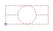
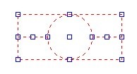
By default, when you select a block, AutoCAD displays only one grip, at the block’s base point. However, what if you want to grip edit the block from some other point in the block. You can do so by displaying the grips of all the objects in the block. Jack Foster sent in a great AutoLISP routine that easily toggles between these modes. To use it, type the following at the end of your acad.lsp file (or create the file if it doesn’t exist and put it in your AutoCAD’s \Support folder).
This will load automatically when you start AutoCAD. Then simply type gb to run the routine. Each time you use gb, the routine toggles the GRIPBLOCK system variable setting. Here you see the results of both settings.
Jack notes that you can use the same method to toggle other system variables that use 0 and 1 as their two values, such as tilemode.
Bruce Hodder sent in this tip: “New for AutoCAD 2000i is the ability to create exponential text values with Mtext using the carat (^) character. First, create a text object using the MTEXT command. Type the exponent value and then the carat character (e.g., 2^). With the Multiline Text Editor still open, select the exponent value and the carat, then right-click. From the shortcut menu, select Stack. To have additional control over the stacking features, simply select the now stacked text and right-click again. From the shortcut menu, select Properties. For additional info and fractional stacking techniques, see AutoCAD Help, keyword “stack.” (Hint: This stacking technique doesn’t work with text created by the commands TEXT, DTEXT or RTEXT, just MTEXT.) Great tip, Bruce!
AutoCAD 2000 sets the default for the cursor at 5% of the screen. Many people like the old full-screen cursor. Abdul Nazar emails from India that you can change the cursor using this prompt.
Command: cursorsize Enter new value for CURSORSIZE <5>: 100
You can also choose Tools>Options and click the Display tab. There you can type in a new cursor size or use the slider bar.
Bob Abernethy contributed a short AutoLISP file that toggles the cursor size from 5% to 100% and back again. He includes a bitmap file that you can use for a toolbar button. Download it.
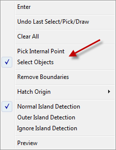
As you place your hatch, you can easily switch from picking points to selecting objects. First define the hatch in the Hatch and Gradient dialog box (the BHATCH command). Then choose either Pick Points or Select Objects to return to your drawing. Start placing the hatch. Then, to switch methods, right-click to open the shortcut menu. Choose the option you want.
You can also undo your last select/pick, change island detection mode, and preview the hatch.
Important: While we don't collect cookies, some of our 3rd-party services (such as PayPal and WordPress) do, to give you a safer and better browsing experience. Read about how we use cookies and keep your personal information secure by reading our Privacy Policy here.