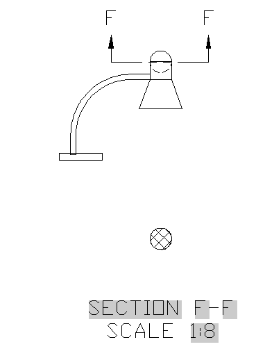
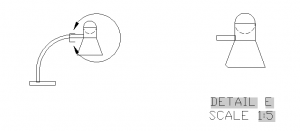
The VIEWBASE command, new for AutoCAD 2012, automates the process of creating 2D views of 3D models. This command creates 2D view objects, which are a little like viewports, but actually a completely separate type of object. In fact, when you display a layout, the first thing you do is delete the default viewport and start from scratch.
2D view objects have been updated in 2013 to let you create details and sections. The new commands are VIEWDETAIL and VIEWSECTION.
See my earlier AutoCAD tip on the VIEWBASE command–before it was updated in AutoCAD 2013.
At the end of this tip, you can watch a video of the process of creating 4 views, plus a section and a detail.
You start by placing at least one 2D view object, because the details and sections are taken from an existing 2D view object.
Create a section view
A section view cuts through the middle of a model. To create a section view, you should be in the 3D Modeling workspace and be on a layout that has an existing 2D view object. Then follow these steps:
- Choose Layout tab> Create View panel> Section drop-down menu and choose the style of section line you want. Your choices are Full, Half, Offset, and Aligned. This starts the VIEWSECTION command.
- At the Select parent view: prompt, click the 2D base object that you want to use for the section.
- At the Specify start point: prompt, pick the point for the start of the section.
- At the Specify end point: prompt, pick the point for the end of the section. The command adds section lines and an identifer letter.
- At the Specify location of section view: prompt, place the section.

You can edit the label and change its font, size, etc.
Create a detail
A detail focuses on a small part of your model. To create a detail, follow these steps:
- Choose Layout tab> Create View panel> Detail drop-down menu and choose either Circular or Rectangular. This starts the VIEWDETAIL command.
- At the Select parent view: prompt, pick the view you want to use for the detail.
- At the Specify center point: prompt, pick a center for the detail.
- At the Specify size of boundary or [Rectangular/Undo]: prompt, pick a point on the border of the detail to specify its size.
- At the Specify location of detail view: prompt, place the detail.
Use the command options
Both commands have options. Here are some of them:
- Hidden lines lets you specify a shading type
- Scale lets you specify a scale
- Visibility lets you turn on and off inteference edges, tangent edges, sheet metal bend extent lines, thread lines, and presentation trails. Some of these options are inherited from Inventor files, which you can use to create 2D view objects. They might not be available for your model.
- Annotation lets you specifier the identifier (the letter) and turn off the label.
- Hatch lets you turn hatching on or off
Here’s a video showing the process of creating 2D views, a detail, and a section.
Do you use these features? Or do you use another method of creating 2D views from 3D models? If so, why? Leave a comment!
- Combine or subtract 2D shapes to create custom shapes - February 17, 2022
- Working with linetype scales - January 18, 2022
- Rename named objects–blocks, dimension styles, layers, and more - December 21, 2021


 Instagram
 LinkedIn
 Facebook
how do you create part views with 2013.I get the whole plan when all I want is a small portion at the left end of my drawing
My AutoCAD 2012 doesn’t have a layout tab like your 2013 version, how can I do this in 2012?
Sorry, I checked your previous instruction and learned about “VIEWBASE”, it pays to read.