You can use fields (AutoCAD 2005 and later) to create automatic labels that provide information about objects.
I’ve covered aspects of this topic before. In “Tutorial: Display the area of an enclosed figure,” I show how to use fields to create a label that displays an area.
In “Tutorial: Create attributes,” I mention that you can use fields in attributes.
In this tutorial, I’ll expand on the idea of using fields in attributes, which are labels attached to blocks. This example shows the use of fields that label geometric parameters of dynamic blocks.
- Open the Block Editor. (Tools> Block Editor or Blocks & References tab> Block panel> Block Editor.
- Create the objects for the block.
- Create the parameter and action you want to label. For example, for a desk, I created a Linear Parameter and a Stretch Action. I renamed the Linear parameter’s label to Length in the Properties palette. If you need further instructions, you can download my complete dynamic blocks tutorial from my “Dynamic blocks tutorial” page.
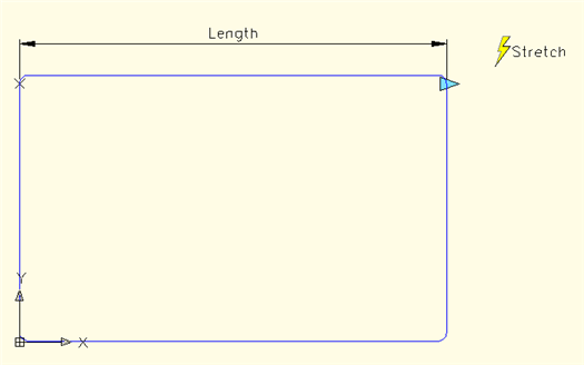
- Start the ATTDEF command (Draw> Block> Define Attributes or Blocks & Reference tab> Atrtributes panel> Define Attributes).
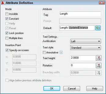
- In the Attribute Definition dialog box, type in a tag name, such as Length. For the Deafult entry, type the text that you want to appear before the value, such as Length: . (Add a space after the colon.) Check the Constant check box so that you won’t get a prompt. The whole point is to make the label automatic. Set the Text Settings section as desired.
- Then right-click in the Default text box or click the Insert Field button at the right to open the Field dialog box. From the Field Category drop-down list, choose Objects. Then choose BlockPlaceholder as the field name. The Block reference property should be the name of the parameter you used. This is Length in our example. Set the format as desired, and click OK.
Note: The Length property is on the list only because I created a parameter named Length. The other properties are available for all blocks.
- You’re now back in the Attribute Definition dialog box, which should look like the figure below. Click OK. Place the label where you want it.
- Save the dynamic block by clicking the Save button in the Block Editor. Close the Block Editor.
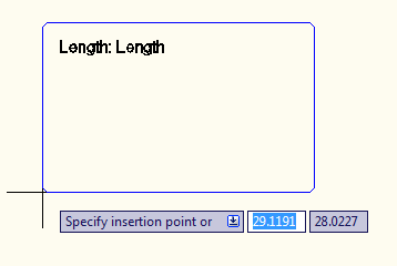
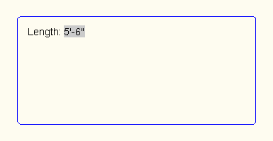
- Back in your drawing, insert the block (Insert> Block or Blocks & References tab> Block panel> Insert). Before you specify the insertion point, you’ll see the following for the label.
After you insert the block, you’ll see the value of the field.
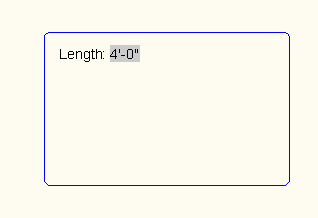
- After you modify the dynamic block, you’ll need to update the field. In this example, changing the length makes the desk longer. Enter updatefield on the command line to update the field.
Tested in AutoCAD 2009.
- Combine or subtract 2D shapes to create custom shapes - February 17, 2022
- Working with linetype scales - January 18, 2022
- Rename named objects–blocks, dimension styles, layers, and more - December 21, 2021

 Instagram
 LinkedIn
 Facebook

If I make the field constant I get ################.
If it is NOT constant it works fine.
I’ve looked through all the other sites I can find but have not found a solution to this.
Can you help?
I have same problem as Peter. Using AutoCAD MEP 2013.
As a work around I used a dimension that stretches with the dynamic block, then turned off all the leader lines.
That’s a great idea!
Great post. Do you know of a way to quickly label a block? Say, perhaps, a leader which allows you to click on the block and automatically attaches the block name on the mText?
I suppose you could write a script or AutoLISP file; otherwise, I’d say that attributes would be the most automated solution.
Does anyone know how to make a field within a leader? I’m looking to make dynamic labels that automatically update in other sheets.
Create a custom property in the file/drawing properties/ dialogue box – use the add option to create your filed. Then when you create the leader, right click in the text area, select insert field and choose from the ‘document’ listing – your custom properties will be shown there.
the issue with the original post seems to be solved by using PRESET in the attdef sequence rather than CONSTANT
Thanks Ellen, for explaining the steps. Very useful.
Thanks James,
Your suggestion made the original post work in AutoCAD 2013.
No matter what I try, when I stretch the block, the number in the Length attribute stays the same. I have to enter the regen command to see the text update. I even have regenauto set to “On”.
Great website! I’ve lost count of how many times you’ve solved my AutoCAD problems.
I’ve created a dynamic block pretty much identical to your desk block, but for closet rods (or shelves or drawer fronts). After I draw the elevations of a closet complete with multiple instances of the closet rod dynamic block, is there a way AutoCAD can calculate total linear feet of all closet rod (i.e. can AutoCAD calculate the total length of all closet rod dynamic blocks used in one drawing)?
The regen command also works for me as a way to update the field – I like it because I don’t have to select the block the way I do with the updatefield command.
Excellent post! Really helpful.
Thanks James for the solution for version 2013, I’ve the same problem on 2012.
I’m looking to have a dynamic block with an array to draw a grid axis. I want every increment to be labelled with the row number. Can I do this using fields?
No matter what I try, I cannot manage to create a dynamic block that gives xyz coordinate values in DECIMAL FEET, I can successfully add the multileader to a point, insert DYNAMIIC FIELD/OBJECT/POINT/POSITION/Which returns DECIMAL(INCHES)
Then by highlighting the field and checking on EDIT FIELD, copy the “field expression” paste to a text file, add the conversion factor of 1/12 “%ct8[0.08333333333333333]”, this was copied from one of the dimensioning fields where scale conversion factor is available.(GREYED OUT IN COORDINATES THOUGH)
So this scaled mleader text field works and regenerates, how can I can’t get it to work as a BLOCK.
My suggestion to Autodesk is unlock the shaded “conversion factor” that is available on the other fileds under “advanced options”
Thanks for considering my post.
I have been doing this but I would like to go one step further by having the depth of a piece of duct entered when the block is inserted and then update the dimensions of the block based upon that input. The width and length are automatic from stretch parameters, but I’d like the entered information to be placed on the end e.g. 1000x600x500, the 500 being the depth of the duct, the other two dimensions being the result of a stretch.
Hi, I’m new to this forum so I don’t know whether a specific link for my question exists.
I’ve defined a block that also contains texts and I would like to insert the block just like an array (e.g., I may MINSERT) but I would like to change the text every time according to a logic.
In other words, consider I have a rectangular shape with “RECT-1” as a default text. I would like to creates N rectangules with “RECT-2”, “RECT-3”,…, “RECT-N” as a label. Does a way to do this exist so I shouldn’t go through DDEDIT?
Thanks in advance!
How I can thank you for this excellent step by step tutorial. Its so easy and still works. Signed up.
Hi
As I wanted the length and width to display I’ve done this in a slightly different way but still using fields.
I drew the rectangle with the line command so that they where separate lines, added the appropriate length parameters & stretch commands.
I then added mtext with 2 fields created by selecting each line and used the length property for each.
When you stretch it a simple redraw commands changes the values.
Hi, could you please make a video showing the process. I’m unable to carry forward as you mentioned. I’m using AutoCAD 2017
[…] Dynamic blocks tutorial […]