AutoLISP offers powerful programming capabilities to AutoCAD, but you don’t need to be a programmer to use it. You can fairly easily create a simple custom command that can make your work go more quickly. In this tutorial, you’ll create a custom command that draws a red circle in any location and with any radius. You could use it to encircle areas where corrections need to be made.
- Open Notepad.
- Type the following:
(defun c:redcircle (/ center pt-on-circumference)
(terpri)
(setq center (getpoint “Specify center of red circle:”))
(terpri)
(setq pt-on-circumference (getpoint center “Pick a point on the circumference:”))
(command “_circle” center pt-on-circumference)
(command “_chprop” “_last” “” “_color” “red” “”)
)
 Save the file in a folder that is in your support file search path. Name it redcircle.lsp (not .txt, the default for Notepad).
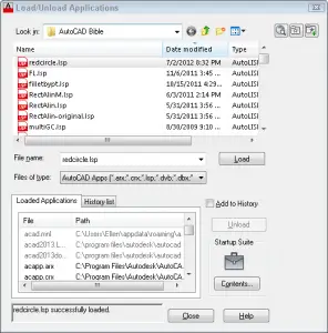
- In AutoCAD, choose Manage tab> Applications panel> Load Application (the APPLOAD command) to open the Load/Unload Applications dialog box.
- Choose redcircle.lsp and click Load. You should see the message: redcirle.lsp successfully loaded at the bottom of the dialog box.
- Click Close.
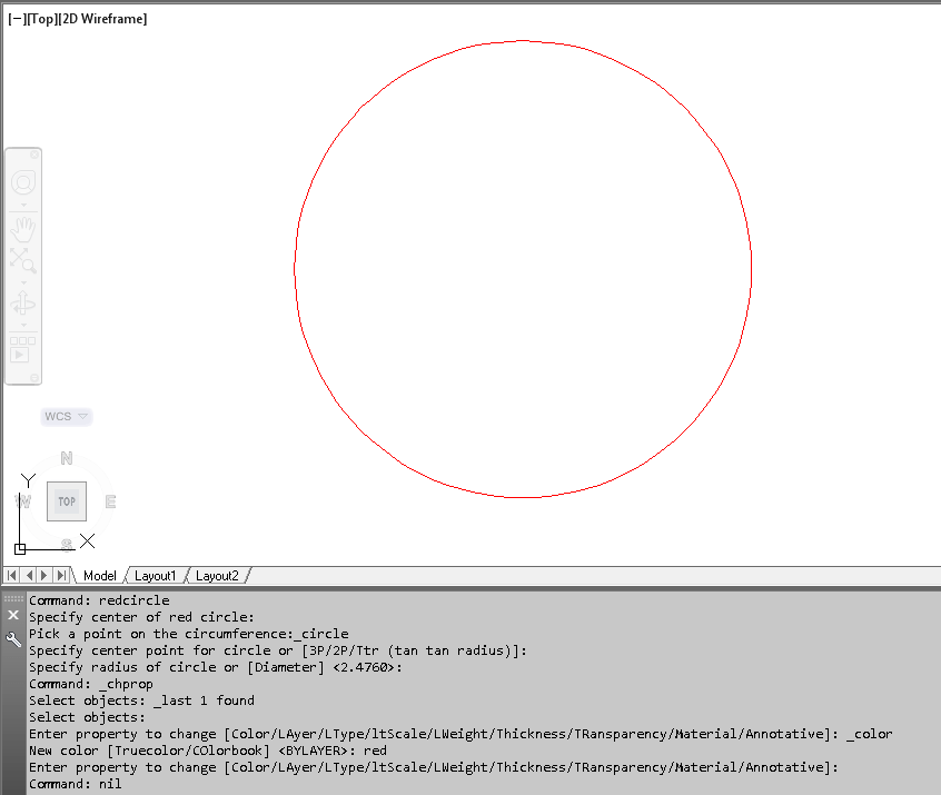
- On the command line, type redcircle and press Enter.
- At the Specify center of red circle: prompt, specify the circle’s center.
- At the Pick a point on the circumference: prompt, pick a point on the desired circumference to specify the radius.
AutoCAD draws the circle and immediately makes it red.

How does it work?
Here’s a line-by-line explanation:
(defun c:redcircle (/ center pt-on-circumference): Everything in AutoLISP is enclosed in parentheses, so you start with an open parenthesis. (You’ll close it at the very end of the routine.) defun followed by c: creates a custom command. Then add the name of the command. The parentheses after the command name are for variables that you’ll define. In this case, they are center and pt-on-circumference. The forward slash and space just have to be there.
(terpri): This function makes the upcoming prompt go on a new line so it’s easy to read.
(setq center (getpoint “Specify center of red circle:”)): The setq function means you’re defining a variable. Its name is center. Then you need another open parenthesis for getpoint which lets the user specify a point. After that is the prompt in quotation marks. You can put anything you want; it should be self-explanatory to the user. After that, you need to close both sets of parentheses.
(setq pt-on-circumference (getpoint center “Pick a point on the circumference:”)): Here again, you’re defining a variable, pt-on-circumference, and getting the point from the user. The only part that isn’t obvious is putting the center variable after getpoint. But you need to do this to create the rubberband line from the center; this is how AutoCAD measures the radius.
(command “_circle” center pt-on-circumference): Using the command function accesses AutoCAD’s regular commands. The underscore before circle allows for translation; it isn’t necessary. You put the command name in quotation marks. Then you give AutoCAD the information it needs to create the circle, namely the center and radius (specified by a point on the circumference). The AutoLISP routine applies the values you gave the variables when you picked the 2 points.
(command “_chprop” “_last” “” “_color” “red” “”): We now use the CHPROP command to make the circle red. This command is just perfect for AutoLISP routines where you want everything to be on the command line, rather than on the ribbon or in a dialog box. Then, you specify the last object created; this is applied to the Select objects: prompt. The 2 empty quotation marks end selection. Then you use the Color option and specify read as the color. All the options go in quotation marks. The final empty quotation marks end the command.
): This closes the first open parenthesis and ends the routine.
How do you use the routine?
Save the file with a filename extension of .lsp in a folder that’s in AutoCAD’s support file search path. If you don’t know how to load an AutoLISP file, see “How to load an AutoLISP program” and “How to load an AutoLISP program quickly.” Then just type the name of the command you created (in this example it’s REDCIRCLE) on the command line.
What else can you create?
Try creating an AutoLISP routine that draws a blue line.
Leave a comment and let us know what custom commands you created!
- Combine or subtract 2D shapes to create custom shapes - February 17, 2022
- Working with linetype scales - January 18, 2022
- Rename named objects–blocks, dimension styles, layers, and more - December 21, 2021

 Save the file in a folder that is in your support file search path. Name it redcircle.lsp (not .txt, the default for Notepad).
 Instagram
 LinkedIn
 Facebook
I tried this lisp
prompt with “too many arguments” error message
Regards,
I just tried it again and didn’t get that. Just copy and paste from the post, including the last closing parenthesis.
Hi Ellen,
The routine indeed doesn’t work if one copy the code from the post and paste to AutoCAD. That is because of smart quotes in the code, you need to substitute them with straight quotation marks are also known as dumb quotes. This code should work:
 (defun c:redcircle (/ center pt-on-circumference)
 (terpri)
 (setq center (getpoint "Specify center of red circle:"))
 (terpri)
 (setq pt-on-circumference (getpoint center "Pick a point on the circumference:"))
 (command "_circle" center pt-on-circumference)
 (command "_chprop" "_last" "" "_color" "red" "")
 )
Maxim
“too many arguments” error message ??:(
Hi ZEESHAN,
See my reply above (about quotation marks)
Maxim
I thinks it is the type of quotation marks being used try ” instead of “ or ”
Jimmy & Maxim, you’re right — curly quotes shouldn’t be used. But if you copy and paste into Notepad, you shouldn’t have any curly quotes. Notepad is handy for stripping out any extra formatting.
hay thanks Ellen,Maxim Kanaev and Jimmy.now its working 🙂
Yay!
;;; AreaText.LSP ver 3.0
;;; Command name is AT
;;; Select a polyline and where to place the text
;;; Sample result: 2888.89 SQ. FT.
;;; As this is a FIELD it is updated based on the FIELDEVAL
;;; or the settings found in the OPTIONS dialog box
;;; By Jimmy Bergmark
;;; Copyright (C) 2007-2010 JTB World, All Rights Reserved
;;; Website: http://www.jtbworld.com
;;; E-mail: info@jtbworld.com
;;; 2007-09-05 – First release
;;; 2009-08-02 – Updated to work in both modelspace and paperspace
;;; 2010-10-29 – Updated to work also on 64-bit AutoCAD
;;; Uses TEXTSIZE for the text height
(defun Get-ObjectIDx64 (obj / util)
(setq util (vla-get-Utility (vla-get-activedocument (vlax-get-acad-object))))
(if (= (type obj) ‘ENAME)(setq obj (vlax-ename->vla-object obj)))
(if (= (type obj) ‘VLA-OBJECT)
(if (> (vl-string-search “x64” (getvar “platform”)) 0)
(vlax-invoke-method util “GetObjectIdString” obj :vlax-False)
(rtos (vla-get-objectid obj) 2 0)
)
)
)
(defun c:AT (/ entObject entObjectID InsertionPoint ad)
(vl-load-com)
(setq entObject (vlax-ename->vla-object(car (entsel)))
entObjectID (Get-ObjectIDx64 entObject)
InsertionPoint (vlax-3D-Point (getpoint “Select point: “))
ad (vla-get-ActiveDocument (vlax-get-acad-object))
)
(vla-addMText (if (= 1 (vla-get-activespace ad))
(vla-get-modelspace ad)
(if (= (vla-get-mspace ad) :vlax-true)
(vla-get-modelspace ad)
(vla-get-paperspace ad)
)
)
InsertionPoint 0.0 (strcat
“%<\\AcObjProp Object(%%).Area \\f \”%pr2%lu2%ct4%qf1 SQ. FT.\”>%”
))
)
[…] View the original article here […]
Here is my blueline lisp. Had to add a set of (“)’s at the end of the line command.
(defun c:blueline (/ pt-1 pt-2)
(terpri)
(setq pt-1 (getpoint “Specify first end point of blue line:”))
(terpri)
(setq pt-2 (getpoint pt-1 “Pick second end point for the line:”))
(command “_line” pt-1 pt-2 “”)
(command “_chprop” “_last” “” “_color” “blue” “”)
)
[…] View the original article here window._wp_rp_static_base_url = "http://dtmvdvtzf8rz0.cloudfront.net/static/"; […]
dear ,
can you please help me to provide autolisp to develop the duct or round shaped elbow to flat pattern.
some one help me to how can change the color automatically when i edit any text or line or object?
Hello! can anyoane to help me to draw a tor in auto LISP? thanks:)
[…] Tutorial: Create a custom command for AutoCAD using … – AutoLISP offers powerful programming capabilities to AutoCAD, but you don’t need to be a programmer to use it. You can fairly easily create a simple custom command … […]
[…] Tutorial: Create a custom command for AutoCAD using … – AutoLISP offers powerful programming capabilities to AutoCAD, but you don’t need to be a programmer to use it. You can fairly easily create a simple custom command … […]
[…] Tutorial: Create a custom command for AutoCAD using … – AutoLISP offers powerful programming capabilities to AutoCAD, but you don’t need to be a programmer to use it. You can fairly easily create a simple custom command … […]
can someone create a Lisp command to rotate, Scale and copy doors
Essentially Align but with copy
can u some one help me how to create a LISP program for Profile in embankment for Railway.
Thank you ..
How do I create a lsp that then I click multiple hatch area of get the area??
i want to make one flanges in lsp file.
what should i type.??
also want to make one assembly.
i used cad lt version 2013. i have wipeout error in cad . when i print that wiped file full dark one wipeout place. pls solve this problem.
Hi Jothi,
There are couple of possible solutions to solve the issue of plotting wipeout in black fill
1. Download Autodesk’s service packs via link below. Install, reboot computer and restart AutoCAD (may only work for AutoCAD 2016 onwards).
2. When plotting, go to Print/Plot/Plot Options/Plot transperency (check box).
Let us know how you go with it.
can u please create a lisp that create layout automatically depending on rectangles in modelspace?
I need a command for fillet with zero radius, to continue until canceled.
Thanks
Hi Thomas,
Enter Fillet command, in the command line you have the option “Multiple”. Type M to select and you can do multiple fillet until canceled.
SO I AM SO NEW TO LISP COMMANDS AND NONE OF THESE ARE WORKING FOR ME, I EITHER GET THE SAME ERROR AS EVERYONE ELSE OR NOTHING-