
This is a guest post by Andreea Georgiana. She is a CAD enthusiast who likes using the power of Computer Aided Design to create cool useful designs, from conception to 3D printing. She has a 21-day AutoCAD course at tutorial45.com.
She says, “Being able to use Computer Aided Design software to bring your ideas to life is one of the things I totally disagree only engineers should be able to do. With the numerous advantages of being able to move past the level of a 3D model to actually having the model 3D printed, anyone should consider learning at least the basics of modifying a CAD model.
“As a CAD hobbyist, wife and mother, I have found many cases where a customized solution designed myself has solved a problem in the exact manner I wanted, thanks to the power of CAD and 3D printing. You can find some free tutorials here.”
* * * * *
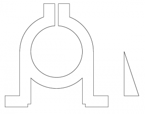
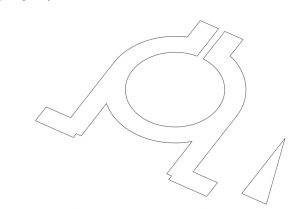
Before I start, here are 2D and 3D images of the model you’ll draw in this tutorial,


Use the images above to help you in completing the 3D model.
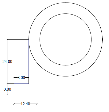
Phase 1: Draw the pipe (circles) and legs (lines)
Make sure the Quadrant and Midpoint in Objects SNAP settings are on. The upper parts of the legs are snapped to the left and right quadrants of the model. Later, you’ll use the Midpoint OSNAP.
Then follow these steps, following the image to the right and below:
- Draw 2 concentric circles with R20 and R14.
- Draw a vertical line downward from the left quadrant of the outer circle 24 units long
- Draw a horizontal line of 8 units toward the left using the lower end of the vertical line you just drew as the starting point.
- Draw a vertical line of 6 units downward from the ending point of the previous line
- Draw a horizontal line of 12.4 units rightward from the ending point of the previous line
- Draw a vertical line of 1.6 units upward
- Draw a line of 1.6 units to the right
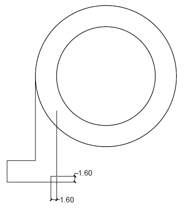

Now follow these steps to trim and mirror the model:
- Use the TRIM command to remove the unnecessary part of the circle. Use the 2 lines that meet the circle as the cutting edges and the part of the circle between them as the object to trim.
- Now mirror this left side using the center of the circle to create the similar shape on the right side of the circle.
- Trim it to complete this step using the TRIM command. You should end up with an image similar to the one below
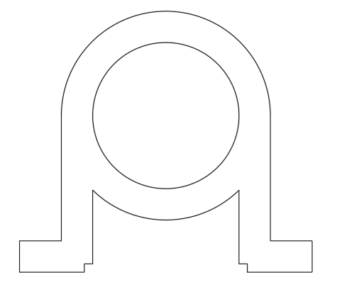
Phase 2: Break the circles at the top
Follow these steps:
- Use the Upper quadrant of the inner circle to draw a vertical line that crosses the outer circle. The length of the line does not matter.
- Use the OFFSET command with the OFFSET dimension set to 1 units to draw 2 lines on each side of the original line.
- Now delete the central line.
 Use the EXTEND command to extend the remaining lines to the inner circle. You might need to zoom in to notice that they don’t actually intersect with the circle.
- Use the TRIM command to trim the two circles as shown in the image below. Use the lines as the cutting edges.

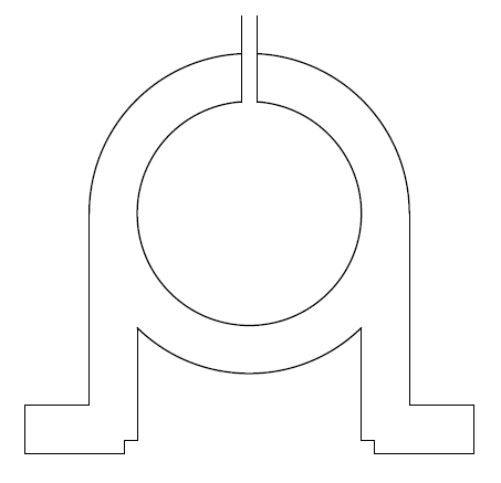
Phase 3: Add the top
Follow these steps:
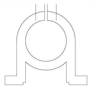
- Use the OFFSET command to offset the left line to the left and the right line to the right with an offset distance of 6 units.
- Trim the new outer lines using the outer circle as the cutting edge., Then trim the top part of the outer circle using the outer lines as the cutting edge.
- You want the outer lines to be 7.2 units long, as shown on the image below and then and you need to close the head using a horizontal line.
- One way to do this is to start the LINE command, type from on the command line and set the offset to 7.2, moving your cursor upward. The draw the LINE horizontally to the left until it intersects the outer vertical line on the left. Then trim the parts of the line that extend past the new horizontal line and trim the part of the horizontal line between the 2 inner vertical lines.

Phase 4: Add the bracing (triangle)
Design the little triangle on the side of the model by drawing a vertical line of 24 units, a horizontal line of 8 units, and then closing the triangle. For now, put it out to the side, separated from the main model. You can draw on top of the existing lines to start, close the triangle, and then select each of the 3 lines and move them to the right.
Phase 5: Prepare for 3D conversion
Use the REGION command and select everything on the drawing area to form 2 regions.
At this point, if you aren’t using a 3D workspace, you should switch to one. Click the little arrow to the right of the Workspace Switching icon on the lower-right corner of the AutoCAD window and choose 3D Modeling.
Phase 6: Change the view and extrude to 3D
Navigate in 3D using Free Orbit. Click on Free Orbit in the navigational bar at the right, click on your mouse, hold, and move until you get a 3D view something like the one you see here. You can drag on the “orb” and its circular handles to get the right view. A keyboard shortcut might work for you: Hold down the Shift key and click and drag with your mouse’s middle (scroll) button.
Use the EXTRUDE command to extrude the model by 28 units and the triangle by 6 units.
On the Visualize tab, in the Visual Styles panel, click the Visual Styles drop-down and choose Shades of Gray.

Phase 7: Assemble the model
Follow these steps:
- Using the View cube at the upper right of the AutoCAD window, switch to the Top view (or go to the Visualize tab, Views panel, and click Top.)
- Use a regular 2D mirror command to mirror right triangle so that you have one on each side of the 3D model.
- Now use 3D orbit again to get a view like you see here.

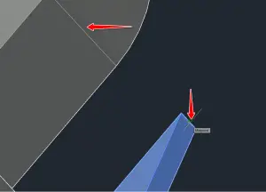
- Use the MOVE command to move the triangle from the midpoint of its upper edge to the midpoint of the 3D line on the circle quadrant. as shown in the image here.
- Turn the view again so you can see the left side of the 3D model and move the left triangle in the same way.
- Start the UNION command, select the 3 objects, and press Enter.
You have just merged the 3 object to form one.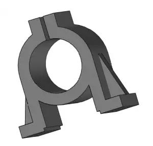
 Phase 8: Add mounting holes to the base
One nice thing with AutoCAD when you model in 3D is that you can still use the power OSNAP and draw 2D lines that will help you design in 3D.
Follow these steps:
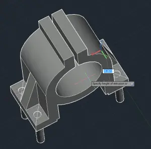
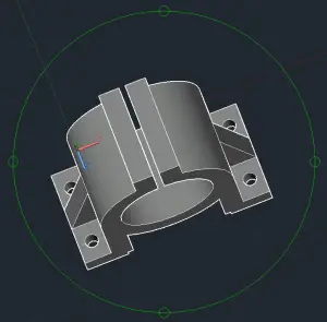
- View the model so you can create the diagonal lines shown on the image at the right. Use the Endpoint OSNAP for the start and end points. You’ll have to change the view several times as you draw the lines.
- Create circles using the midpoint of each of the lines you just created as the center and a radius of 2.
- Extrude the circles downward so the height goes completely through the model. You can select and extrude them all at once.
- Subtract the 4 cylinders from the model. Start the SUBTRACT command, select the model and press Enter, then select all of the cylinders and press Enter.
- Delete the diagonal lines.
Phase 9: Fillet the sharp corners
The FILLET command will help you round some of the sharp edges. Follow these steps:
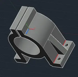
- Select the edges with the red mark. To make it easier to select just the edge, on the Home tab, in the Selection panel, choose Edge from the Filter drop down. (You might see No Filter, Vertex or Face before you make this choice.)
- Use the FILLET command to round their shape with a dimension of R = 0.8 units. To FILLET, start the command, select the appropriate edge, enter 0.8, and press ENTER 2 times.
- Repeat the process with the opposite edge.
Phase 10: Add holes in the top
This is the final phase. Follow these steps:
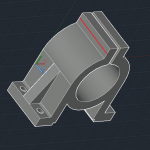
- Draw the line shown on the image below using the midpoints of the two edges.
- Create a circle of radius 2 units using the center of the drawn line.
- Delete the line you just drew and create 2 lines using the quadrant of the circle and two edges you previously used. You might have to rotate the model to find the object snaps.
- Now, use the center of those lines to create 2 circles of radius 2.
- Delete the lines and extrude the 3 circles using the EXTRUDE command and make sure they go all the way through the model.
- Subtract those cylinders from the 3D model using the SUBTRACT command.
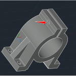
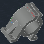
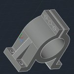
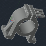
Congratulations!
You should end up with the following model. You might need to FILLET few more edges to have your model look identical to the model on the exercise. I hope this has been helpful to you!
Andreea has a 21-lesson course here that you might find valuable.

- Combine or subtract 2D shapes to create custom shapes - February 17, 2022
- Working with linetype scales - January 18, 2022
- Rename named objects–blocks, dimension styles, layers, and more - December 21, 2021

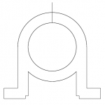
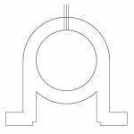 Use the EXTEND command to extend the remaining lines to the inner circle. You might need to zoom in to notice that they don’t actually intersect with the circle.
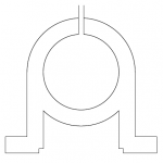
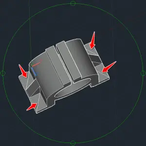 Phase 8: Add mounting holes to the base
 Instagram
 LinkedIn
 Facebook

Hi Ellen, A really good read I must say. Andreea has nicely displayed how to leverage Computer Aided Design to create cool useful designs, across conception to 3D printing.
The only place I beg to differ is “using computer Aided Design software to bring ideas to life by people other than engineers”. I nowhere claim that it would not fetch desired results. I strongly feel that learning the basics of modifying a CAD model as against implementing CAD solutions to resolve design challenges; are altogether two different ball games.
If it would have been that convenient an approach, things across the engineering domain and engineering professionals’ fraternity would have been drastically different.
Please feel free to counter my views.
These guide lines are very beneficial for the beginner to create a 3d-model by this as they can easily learn and make their own model as the need of a little hard work and efforts to build their career in this field and to achieve success in this field.
Thanks Gail for sharing insights for realistic ways to monetize a 3D printing. Let’s keep spreading the word about the value of 3D model. they have deep immersive knowledge about their audience -that brands or startup companies could pay for.
Thanks, Ellen, this blog has a great concept of 3D modeling, the step by step formula to doing that gives the beginners a good platform.hope everyone just knows your contribution to the designing.and I am also waiting for your next blog.
In phase 7 step 6 to assemble the model, it’s easier to mirror the triangle on the right side over to the other side rather than to also move the other triangle into place.
Thanks for sharing such wonderful guidelines on creating 3D model. These are extremely useful for beginners. I hope you will come up with more such interesting articles.
This is really cool! I will also try creating a tutorial on SelfCAD- New CAD program https://www.selfcad.com and see if i will post it here.
Thanks Gail for sharing insights for realistic ways to monetize a 3D printing. Let’s keep spreading the word about the value of 3D model.
I have seen your work, It really good. I hope you continue to do good work.
Nice blog Content.It is very informative and helpful. Please share more content. Thanks.
First of all, thanks for sharing this tutorial these will help a lot for beginners and guide them easily as you have explained well and beginner can easily learn a lot of things by the help of your tutorial and also help them to make first 3d model.
Thanks for sharing
Thanks for this information. It was really helpful.
Hi, ellen Nice to read the blog of Andreea. Specifically, I think the blog is for beginners of computer-aided design. Andreea has covered the basics of design like centre points, fillet options, coincided holes, etc.
I request to use some critical drawings so it will cover all the tools of CAD. because I used very critical drawings to create 3D drawings. Currently, I’m creating critical real estate drawings on cad.
Hi Ellen,
Thank you for the nice tutorial. Your tutorial jump started my interest in 3D drafting from 2D. Although I have done 3D drafting years ago, your tutorial provided an excellent brushing up exercise.
You are a very talented person. Thank you for sharing your talent and leadership with so many of us. God bless!
Hi Ellen,
Thanks for your step by step tutorial. This is very helpful and useful for my future use on 3d model.