You may want to draw in 3D, but if you need to deliver drawings in 2D, in several views, how do you convert them? In other tips, “Converting 3D drawings into 2D drawings,” and “Convert a 3D solid to a 2D drawing with a hidden view,” I’ve discussed some methods, but this excellent method uses the FLATSHOT command. It was introduced in AutoCAD 2007.
The FLATSHOT command offers you much more flexibility if you want to create the drawing in model space with several views. In this tutorial, we’ll convert this solid to a 3-view drawing.
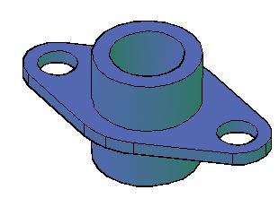
These steps assume that you are in the 3D Modeling workspace.
- Make a copy of your drawing because at the end of the process you’ll delete the 3D objects.
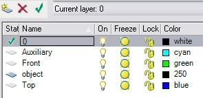
- Create a layer for each of the views. As you create each view, you’ll need to turn off the layers for the previous views. In this example, I made 3 layers for the 3 views–Top, Front, and Auxiliary.
- FLATSHOT works best with parallel projections. To switch to a parallel projection, on the View tab, click Orbit. Then right-click and choose Parallel. Press Esc to end the ORBIT commeand.
- Change the value of UCSORTHO to 0. You’ll be switching to orthographic views, but you don’t want to change the UCS each time you switch to a orthographic view.
- Make the layer of your first view current, in this case, the Top layer on the Home tab’s Layer drop-down list.
- On the View tab’s View drop-down list, choose the corresponding viewpoint (Top in this example).
- To start the FLATSHOT command, go to Home tab> Sections panel (expanded)> Flatshot, or just type the command name. The Flatshot dialog box opens. In this situation, in the Destination section, choose Insert as New Block, as you see here.
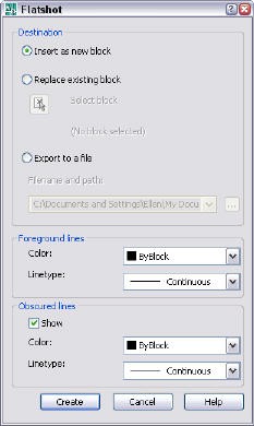
- At the bottom of the dialog box, you choose options for foreground and obscured lines. These options determine how the 2D profile will look. You can choose the colors for the profile and for obscured lines. To create a hidden view, uncheck the Show check box.
- Click Create. The dialog box closes and you’re back in your drawing.
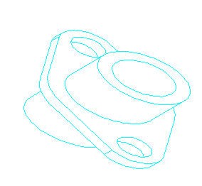
- Follow the usual prompts to insert the block. The exact location at this point is not important; you can move the blocks later. For some reason, the insertion point is somewhere off the block, so you may need to zoom out to see where to place the block (or to find the block after you place it). Don’t worry if one or more of the views looks wrong. Because FLATSHOT is laying the profiles on the XY plane, from another viewpoint the profiles can look wrong, like you see here.
- Turn off the layer for the previous view. (Click OK when the dialog box tells you you’re turning off the current layer.) You need to do this because FLATSHOT works on all layers that are on or thawed. So you turn off the previous layer so that the next FLATSHOT operation doesn’t make a block of your previous 2D blocks! In our example, we turned off the Top layer.
- Repeat steps 5-10 for each of your views.
- Turn on all of your layers. Switch back to Top (plan) view. Your 2D blocks should look right now.
- Delete your original 3D object and move your 2D blocks to the desired location. Here’s the result, with top and front views and a hidden auxiliary view.
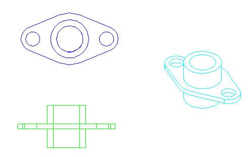
This method is easy and effective when you need to create several 2D views of a 3D model.
- Combine or subtract 2D shapes to create custom shapes - February 17, 2022
- Working with linetype scales - January 18, 2022
- Rename named objects–blocks, dimension styles, layers, and more - December 21, 2021

 Instagram
 LinkedIn
 Facebook

[…] FLATSHOT command: Here’s a tutorial on it. […]
[…] For another way to convert 3D drawings to 2D drawings, see Convert a 3D drawing to a 3-view 2D drawing in model space […]
Hi Helen useful but I couldn’t get dimensions to register to the proper points in paper space except in Top View.
Thanks for the tutorial through
Paul J
It works fantastic, thank you. Funcionó de maravilla, muchas gracias.
thank you so much!!
it is so usefull for me .thank you so much..
I always find it better to use the SOLPROF command, although the FLATSHOT command is a novel way of creating flat isometric views.
it’s working but for piping it’s not make center line
it’s not problem
[…] แปลบางส่วนจากบทความของ AutoCAD Tips Blog […]
Hi Helen, very useful, thank you so much!!
What are those extra lines in the front view, in the holes in the tabs? And how do you get it to show hidden lines?
thank u.. it’s very useful for me..
pls bear with me..cos im new to this
i need to convert a 3d model into 2d dwg, cn i do this directly in inventor fusion after opening it from stp file?
is there a ‘guide’ that can help me’step by step’ how to work this out?
note: im using autocad for my 2d dwgs..
Nice but I have model converted from 3D editor to Cad which is mostly in POLYFACE MESHES.. Tried few times a FLATSHOT and seems to me it works only with “solids and surfaces” as it was continuosly telling me it can’t find any..
Good tutorial and very helpful, by the way, can you tell me how to make the dimension appear in this methods?? Thanks
This command helped me alot
Nice! Thank you so much!
I have got what I was looking for.
Thank you.
Great!!!
Thank you very much . It has been very useful to me .
Really Good work n nice thank a lot.
Plzzz let me know the dimensions and name of the equipment plz as early as possible