Have you noticed how grip-editing a viewport is different from grip-editing a rectangle?
When you grip-edit the upper-right corner of a viewport to stretch it, the viewport keeps its rectangular shape. You can freely choose your new corner location, so you’re not just scaling. You can change the proportion between the width and height, all without losing its rectangle-ness.
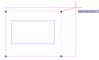
Stretching a viewport
But when you grip-edit the upper-right corner of a rectangle, the rectangle is distorted. The rectangle doesn’t know that it’s supposed to remain a rectangle. AutoCAD just thinks of it as a 4-sided, closed polyline. Indeed, select it and check in the Properties palette (Ctrl+1) and you’ll discover that it is indeed just a polyline.
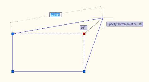
Stretching a rectangle in AutoCAD
AutoCAD 2010’s geometric parameters can help you easily create a rectangle that knows it’s a rectangle. And, what is a rectangle? Well, “rect” means right, as in 90°. “Angle” is self-explanatory. So, we need to ensure that the angles will stay 90°.
Here’s how:
- Draw a rectangle.
- Go to Parametric tab> Geometric panel, and click the Perpendicular button.
- At the Select first object: prompt, click the top horizontal line of the rectangle.
- At the Select second object: prompt, click the left vertical line. You’ll see the Perpendicular icon near the upper-left corner of the rectangle.
- Repeat the process for the two lines that meet at the lower-left corner and the lower-right corner.
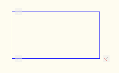
A rectangle with 3 perpendicular geometric constraints
Note: If you try to do all 4 corners, you’ll get a message telling you that AutoCAD can’t apply the constraint. That’s because when you have 3 corners constrained to perpendicular, the last corner is superfluous, and is therefore an overconstraint.
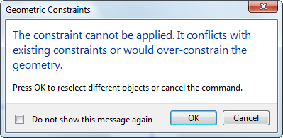
You can’t overconstrain an object in AutoCAD
Now, you can grip-edit that upper-right corner and it will behave just like a viewport!
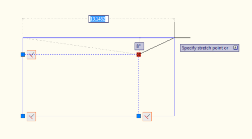
The rectangle now stretches like a viewport!
Here’s a quick video of the same operation:
- Combine or subtract 2D shapes to create custom shapes - February 17, 2022
- Working with linetype scales - January 18, 2022
- Rename named objects–blocks, dimension styles, layers, and more - December 21, 2021

 Instagram
 LinkedIn
 Facebook
I think it would take less time just to redraw the rectangle.
For one time, you’re right. But to create a kind of dynamic object that might be changed often, it would be very useful.
Ellen
i wonder if there is a way to do that in autucad 2006? before the patrametric tab and functions have been added.
thanks
Mishael
2006 supports dynamic blocks. Setting this up as a dynamic block would suit your needs.
Craig,
Please share the settings you’d use for the dynamic block.
Ellen
You can certainly do it with two linear stretch actions (and two grips) but I haven’t found any way to do it with just one grip. It’s a shame there’s no backward compatibility with the new constraints. That takes them right off the table at my office.
You can do it with an XY parameter with only one grip and two linear stretch actions (one horizontal and one vertical) associated to that same grip.
Can you provide more details? I can’t get it to work.
I can create the XY parameter with one grip.
When I add horizontal stretch action, and choose that grip, then how do I define the stretch frame?
Same question for the vertical stretch action.
When I figure it out, I’ll made a video.
Ellen
Ok, got it! Thanks Joel! I’ll post the video as a separate post.
Ellen
[…] a rectangle with an adjustable corner, Part 2: Using a dynamic block In a previous post, “Create a rectangle with a flexible corner,” I showed how to create a rectangle whose upper-right corner is strechable, creating a […]
Is is possible to create this on Autocad 2010LT, if not is it possible to upload a DWG with a Geometric rectangle in, so I could use one. Thankyou so much
Tenniscelebrationparty
I don’t think that LT has parametric constraints.
I really enjoy reading and also appreciate your work
This is an easy & quick tip. Will this still work in AutoCAD 2020?
Thank you!