Visual styles were introduced in AutoCAD 2007. They bring your ability to control how objects look to a whole new level. You can control how faces and edges look, as well as display a background, shadows, materials, and lights — all without rendering the drawing.
Visual styles are important when you want to create a presentation-quality drawing that still functions like a drawing, meaning that it can be edited. They can also help you visualize your drawing more clearly. Here you see the default 2D wireframe visual style.
To create a visual style, open a drawing with a 3D model, display it in a 3D view (Southeast Isometric, for example), and follow these steps:
Open the Visual Styles Manager by choosing Tools> Palettes> Visual Styles, or use the VISUALSTYLES command on the command line.
It’s useful to use an existing visual style as a basis for the new one, and in this tutorial, we’ll use the Conceptual visual style as a basis, so right-click the swatch for the Conceptual visual style, and choose Copy.
Right-click in the swatches area, and choose Paste.
Right-click the new swatch that appears (it’s called Copy 1 of Conceptual), and choose Edit Name and Description.
In the Edit Name and Description dialog box, enter MyConceptual for the name. In the Description box, enter Sketch. Click OK. (Note: Recent releases of AutoCAD come with a visual style called Sketchy, but you’ll still learn about visual styles by following this tutorial.)
In the Face Settings section, notice that the Face Style is Gooch, the Lighting is Smooth, and the Opacity is a negative number, meaning that it’s off. Also, the Material Display is set to Off and the Color is set to Monochrome. The Monochrome Color should be white (255,255,255). In the Environment Settings section, Backgrounds should be set to Off. In the Lighting section, Shadow Display should be set to Off.
In the Edge Settings section, you may need to expand and scroll down. The Show settings should be set to Facet Edges. This places a line at the edge of each face.
Set the Color to Red, or another color that contrasts with your models.
In the Edge Modifiers section, click the left, small button to the right of the name of the section. If you watch carefully, you’ll see that this changes the value of the Overhang item from -6 to 6, turning it on.
Click the right, small button in the same area. Now, when you click the Jitter item, you have a down arrow giving you other options.
Click in the Jitter item, and choose Low from the drop-down list.
Set the Crease Angle to 40. This reduces the number of facet lines on curves. If you have curved faces in your drawing, try setting this item to 20, then to 1 (the minimum), then to 180 (the maximum) to see the difference. The results will depend on the curved faces in your drawing. Set the Crease Angle back to 40. (For some reason, I was only able to use the up and down arrows to change this value; I couldn’t type a value.)
In the Silhouette Edges section, set the Width to 7.
Click the Apply Selected Visual Style to Current viewport button (above the settings but below the style thumbnails), to see the results of the changes so far.
In the Occluded Edges section, set Show to Yes. This lets you see hidden edges, but without losing the feel of a solid. Again apply the visual style to the viewport.
To save the visual style for use in other drawings, open the Tools Palette (Ctrl+3). Right-click the gray bar and choose Visual Styles from the list of palettes at the bottom.
Drag your new visual style to any place on the Visual Styles tool palette.
To use the visual style, you can now choose it from the Tool Palette window in any drawing.
Here’s the final result. Experiment with other settings. There are a lot to choose from!
Do you create custom visual styles? What are the settings you use most?
In 3D drawings, you’ve had some display options for years: wireframe, hidden, and various types of shading. These were the SHADE or SHADEMODE options on the View menu. AutoCAD 2007 introduced a new concept: visual styles. The main difference is that you can customize them to create your own visual style.
AutoCAD comes with several preset visual styles which are comparable to the old SHADEMODE options:
* 2D Wireframe: Like the 2D Wireframe of previous versions, it uses the 2D model space background. * 3D Wireframe: Uses a shaded UCS icon and the new 3D background, which is gray by default. * 3D Hidden: Like the old Hidden display. * Conceptual: Shades objects using the Gooch method of shading (developed by Bruce and Amy Gooch). A non-photo-realistic style, using gradations of warm and cool colors. Conceptual shading is very pretty. This model is shades of green and blue because the layer is blue. Try out other colors to see the results.
* Realistic: Displays materials that you add. Without materials, it is like the old Gouraud shading with edges.
AutoCAD 2011 introduced several additional preset visual styles.
Follow these steps to create your own visual style. Ours will be similar to the Conceptual style, but with heavier outlines, and overhang and jitter effects.
1. Create a layer whose color is blue and make it current. (You can use any color, but black/white doesn’t show off the shading very well.) 2. Create the model shown earlier or use one you have. You’ll see the results best if you include some curved faces. 3. Click the View tab, then click Visual Styles Manager in the Palettes panel. 4. Right-click the Conceptual swatch choose Copy. 5. Right-click anywhere in the swatch area again and choose Paste. (To start from scratch, click the Create New Visual Style button in the palette’s toolbar. This creates a style that is similar to the Realistic visual style.) 6. Right-click a third time and choose Edit Name and Description. Name the visual style Outlined Conceptual and enter a description. I used Conceptual with outline, overhang, jitter 7. Scroll down to the Edge Settings section. Set the Show value to None. 8. Change the Silhouette Edges-Width setting to 6. 9. In the Edge Modifiers section, click the Overhanging Edges and Jitter Edges buttons to turn on these features. The Overhang value changes from -6 to 6. 10. Select the model. 11. From the View tab, choose Outlined Conceptual from the Visual Styles drop-down list to see the result.
Note that visual styles are saved with the drawing. In order to make a visual style available in other drawings, save the drawing as a template, or open your template and save the visual style there. In the Visual Styles Manager, there’s also a button to Export the Selected Visual Style to the Tool Palette.
The FLATSHOT command offers you much more flexibility if you want to create the drawing in model space with several views. In this tutorial, we’ll convert this solid to a 3-view drawing.
These steps assume that you are in the 3D Modeling workspace.
Make a copy of your drawing because at the end of the process you’ll delete the 3D objects.
Create a layer for each of the views. As you create each view, you’ll need to turn off the layers for the previous views. In this example, I made 3 layers for the 3 views–Top, Front, and Auxiliary.
FLATSHOT works best with parallel projections. To switch to a parallel projection, on the View tab, click Orbit. Then right-click and choose Parallel. Press Esc to end the ORBIT commeand.
Change the value of UCSORTHO to 0. You’ll be switching to orthographic views, but you don’t want to change the UCS each time you switch to a orthographic view.
Make the layer of your first view current, in this case, the Top layer on the Home tab’s Layer drop-down list.
On the View tab’s View drop-down list, choose the corresponding viewpoint (Top in this example).
To start the FLATSHOT command, go to Home tab> Sections panel (expanded)> Flatshot, or just type the command name. The Flatshot dialog box opens. In this situation, in the Destination section, choose Insert as New Block, as you see here.
At the bottom of the dialog box, you choose options for foreground and obscured lines. These options determine how the 2D profile will look. You can choose the colors for the profile and for obscured lines. To create a hidden view, uncheck the Show check box.
Click Create. The dialog box closes and you’re back in your drawing.
Follow the usual prompts to insert the block. The exact location at this point is not important; you can move the blocks later. For some reason, the insertion point is somewhere off the block, so you may need to zoom out to see where to place the block (or to find the block after you place it). Don’t worry if one or more of the views looks wrong. Because FLATSHOT is laying the profiles on the XY plane, from another viewpoint the profiles can look wrong, like you see here.
Turn off the layer for the previous view. (Click OK when the dialog box tells you you’re turning off the current layer.) You need to do this because FLATSHOT works on all layers that are on or thawed. So you turn off the previous layer so that the next FLATSHOT operation doesn’t make a block of your previous 2D blocks! In our example, we turned off the Top layer.
Repeat steps 5-10 for each of your views.
Turn on all of your layers. Switch back to Top (plan) view. Your 2D blocks should look right now.
Delete your original 3D object and move your 2D blocks to the desired location. Here’s the result, with top and front views and a hidden auxiliary view.
This method is easy and effective when you need to create several 2D views of a 3D model.
One of the nicest new features of 2007 is the ease with which you can change your viewpoint using a poorly-documented keyboard shortcut for 3D Orbit. Press and hold Shift and press your mouse’s wheel (or middle button) to temporarily and transparently enter 3D Orbit.
While doing this, use that wheel to drag in any direction and your viewpoint changes. When you’re done, just release the Shift key and mouse wheel.
This is so fast and easy, you won’t believe that you once entered a 3D Orbit mode, changed your viewpoint and then exited. No more entering and exiting. Just use the keyboard combination and change your viewpoint. You’ll find yourself doing this many times as you work, completely intuitively.
Even better, you can still use the trick of selecting an object to orbit just that object. This is a great technique when you have a large drawing but want to focus on one object.
This little keyboard shortcut ranks up there as one of my favorite 2007 features.
The SOLIDEDIT command (open the Edit Solids toolbar for easy access) has an option that lets you separate solids. Many people have been confused about this option, because it requires that the solids be non-touching.
So aren’t they already separate? It turns out that the UNION command can combine non-touching solids. Think of it as a way of grouping solids. Then, the Separate option can separate these solids.
You can create 3D objects by adding a thickness to them. These objects function like 3D surfaces. For example, you can create a cylinder from a circle or a box from a rectangle.
To add thickness, select the object and open the Properties palette. Choose the Thickness property and change the number in the Thickness text box. Press Enter.
Funnily enough, when you create objects using thickness, only objects that you drew starting with a circle, a wide polyline, or using the SOLID command (which is a 2D command, just to confuse you), have tops. If you start with a rectangle or polygon, you don’t get a top.
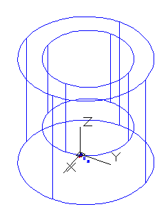
You can’t see the difference until you use the HIDE command or shade the objects. Here you see some 3D objects before hiding.
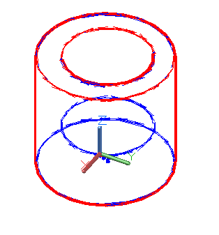
Here you see the same objects after hiding. The one that I created from a rectangle doesn’t have a top (or a bottom).
If you need a box that has a top or bottom, you have several choices:
Use a wide polyline and add thickness
Use the BOX command on the Solids toolbar to create a true solid
Use the _AI_BOX command on the Surfaces toolbar (the button’s tooltip just says “Box”) to create a true surface
Surveyors, land-use engineers, and architects often need to create contours that show the elevation of land. You can easily do this using the SPLINE command.
First, set an easily visible point style. Choose Home tab> Utilities panel drop-down, Point Style in the Drafting & Annotation workspace. (This is the DDPTYPE command or PDMODE system variable.)
Then use the POINT command to insert the points into the drawing. If you have a list of points in an external file, you can create a script file that sets PDMODE, starts the POINT command, and inserts all the points. You’ll need to strip the external file of everything except the points and then format them (in a text-only file) so that each one is on a separate line.
Finally, use the SPLINE command. Use the NODE osnap variable to snap to the points.
Readers of my books often ask me how to convert a 3D drawing into a 2D drawing — either to simplify dimensioning or for presentation purposes. Here are three techniques:
If your drawing is made up of solids, you should use SOLVIEW and SOLDRAW or SOLPROF, because they provide the most accurate results.
SOLVIEW automates the creation of floating viewports and orthogonal views of your model. SOLVIEW also creates a special layer for dimensioning. For a view that you have named “front,” look for a layer called front-dim. You can use these layers to create dimensions in paper space.
SOLDRAW works with the views created by SOLVIEW and creates 2D profiles, including hatching for sections.
SOLPROF requires that you create your own floating viewports and that you start on a layout in model space. This command then creates profiles. You can create hidden views by choosing Yes at the “Display hidden profile lines on separate layer?” prompt and then freezing or turning off the layers that represent hidden lines.
Top Customization Tips Every AutoCAD User Should Know
AutoCAD is meant to be customized, but customization is one of the most complex features of AutoCAD. Gain the knowledge you need to be a master at customizing AutoCAD!
If you drawing contains non-solids, your best bet is to create a DXB file (a binary file containing all the specifications of your drawing) and then import that file into a new drawing. These results are not as accurate, but acceptable for most presentation purposes. Here are the steps:
Click Next. On the Begin screen, choose the location for your plotter, My Computer, Network Plotter Server, or System Printer. Click Next.
On the Plotter Model screen, choose AutoCAD DXB File from the Manufacturers list. Click Next.
On the Import Pcp or Pc2 screen, click Next unless you want to import an existing plotter configuration file.
On the Ports screen, Plot to File should be checked. Click Next.
On the Plotter Name screen, you can keep the default name (DXB File) or type a new name. Click Next and then click Finish. You have now finished the setting up of the DXB plotter. You don’t need to to this step again.
In your drawing, set up the view you want to plot.
Click a layout tab and create a floating viewport. (By default the Page Setup dialog box appears. Click OK to create one floating viewport.)
If you want a hidden view, select the viewport itself (the border). Right click and choose Hide Plot > Yes. If you don’t want the viewport border itself to appear, put it on a different layer and freeze the layer.
Choose Plot from the Standard toolbar. On the Plot Device tab, chose DXB File.pc3 (or whatever you named your DXB plotter).
In the Plot to File section, name your file and choose a location. (You can click the ellipsis button to browse to a location.) Note that the Plot to File checkbox appears grayed out.
Click OK to create the DXB file.
Open a new drawing and choose Insert > Drawing Exchange Binary. Locate and choose the file you created and click Open. (If you model is rotated, just use the ROTATE command.) You now have a 2D representation of your 3D drawings, everything broken down into lines.
A new Express Tools command is Flatten, which converts a 3D drawing to 2D. The results depend on the viewpoint you are using when you execute the command. For example, a cylinder viewed using the SE Isometric viewpoint becomes a set of polylines. If viewed from the top, the cylinder becomes a circle, because that’s what you see. Since AutoCAD 2007, there’s a similar FLATSHOT command.
Koyilada Venkata Rao sent in this tip for converting a 3D solid to a 2D drawing. His tip explains how to create a hidden view, but you can create a wireframe as well. It uses the SOLPROF command to create a profile. By transferring the results to another file, you get a solely 2D drawing.
Here are the steps:
Create the 3D model. I worked with one object, but you can work with more than one.
Set up the view that you want.
Start the UCS command and use the New>View option to set the XY plane parallel to the view.
Choose a layout tab. By default, a viewport is created automatically. Otherwise, choose View>Viewports>New View (MVIEW command) and create a viewport.
Double-click inside the viewport to switch to model space.
Type solprof on the command line. At the prompt, select the 3D model and accept the defaults (Y each time) for all three prompts. You should now see a wireframe profile. (The profile is one object.)
You’ll now see two new layers in the Layer Control drop-down list. One starts with PV- and could be PV-ad, PV-125, or any suffix. The other starts with PH- and has the same suffix. The PV layer contains the front parts of the profile (V stands for visible). The PH layer contains the hidden parts (H stands for hidden). Make the PV- layer the current layer.
Freeze all other layers. Now you see the hidden view. If you want a wireframe, don’t freeze the PH- layer.
Press Ctrl+C and select all objects (which won’t include the frozen layers) to copy the profile to the Windows Clipboard.
Start a new drawing.
Press Ctrl+V to paste in the profile and specify any point to place it. You should see the profile looking exactly the same as before. (If the angle looks wrong, reproduce the viewpoint you had in the previous drawing and set the UCS to View again.)
Start the EXPLODE command (because the profile comes in as a block) and select all objects. (Skip this step if you want to leave it as one object.)
The new profile may not be the same scale as the original. If not, measure any length in the original drawing.
Use the SCALE command and select all the objects. Then use the Reference option. At the prompt to specify the reference length, specify the beginning and end of the length you measured, that is, the same object in the new drawing.
At the prompt to specify the new length, enter the length that you measured to scale the model to that new length.
Here is the model in the new drawing. Each line (and spline) is a separate object.
One of the exciting new features of AutoCAD 2007 was to allow you to use the SLICE command to carve a solid with a surface. Previously, SLICE was limited to planes. Because you can create such interesting surfaces, you can now carve out solids to make solids that appear molded.
Follow these steps:
Create the solid. Here, I started with a simple BOX.
Create the surface. I suggest creating a different layer with a contrasting color for the surface. I started with an arc. Then I moved it into place and used the EXTRUDE command. While extruding, I simply dragged it so that it cleared the top of the box.
Feel free to add other surfaces if you need them. I added two more surfaces.
Start the SLICE command. It’s on the extended section of the 3D Make control panel of the Dashboard so you have to click the double-down arrows to find its icon. Or just type it in.
At the Select objects to slice: prompt, select the box (or other solid). Press Enter to end object selection.
At the Specify start point of slicing plane or [planar Object/Surface/Zaxis/View/XY/YZ/ZX/3points] <3points>: prompt, choose the Surface option.
At the Select a surface: prompt, select the surface you want to use for slicing.
At the Select solid to keep or [keep Both sides] <Both>: pick the side you want to keep. I picked the larger portion of the box.
Repeat the process for other surfaces if you had more than one.
When you’re done, turn off the surface layer to see the results. Here you see it from two different viewpoints.
Important: While we don't collect cookies, some of our 3rd-party services (such as PayPal and WordPress) do, to give you a safer and better browsing experience. Read about how we use cookies and keep your personal information secure by reading our Privacy Policy here.