Autodesk 360 is a cloud-based online service is used primarily for storing and reviewing drawing files on the go. There is also AutoCAD WS, which is a web app that lets you edit DWG files online, including on mobile devices. In this post, I’ll focus on Autodesk 360.
You can add apps for specific capabilities and you can collaborate on drawings. You can use the platform to communicate with collaborators, making it a social networking work tool. You can automatically sync drawings between your computer and Autodesk 360.
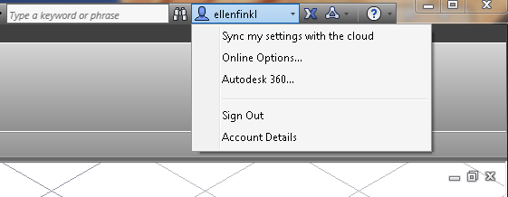
You need to create an Autodesk 360 account or you can sign in with an existing Autodesk Universal ID login. In AutoCAD 2013 and 2014, click the account box at the upper-right corner of the screen and choose Autodesk 360 to log in.
New Features
Autodesk 360 has recently added some new features:
Autodesk 360 Mobile: With the Autodesk 360 Mobile app, you can access your data from your iOS or Android device.
Commenting on DWFs and DWGs: You can comment within a file you are viewing and reply to comments.
Download folders: You can download an entire folder and its contents as a single ZIP file.
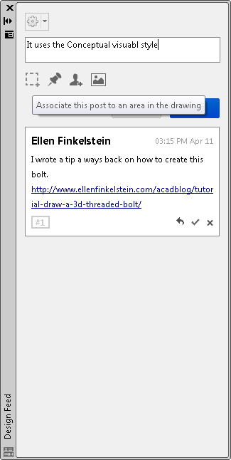
In AutoCAD 2014, by default, the Design Feed palette appears where you can save a drawing to Autodesk 360, add comments, associate a comment with a point or area, add an image to your comment, or tag a colleague. This palette is new for AutoCAD 2014.
If you don’t see the Design Feed palette, go to the Autodesk 360 tab and click the Design Feed button.
Save and open drawings with Autodesk 360
To upload a drawing file to Autodesk 360, you can use the Save As dialog box and choose Autodesk 360 in the left-hand panel.
You can also go to the Online or Autodesk 360 tab and choose Share Document.
You can open a drawing from Autodesk 360 from the Select File dialog box in the same way. You can download a drawing to edit it offline. You can access the Autodesk 360 website on the Online/Autodesk 360 tab. Click Autodesk 360 (in AutoCAD 2013) or Launch Website in (AutoCAD 2014). Of course, you can just go to the website directly in your browser.
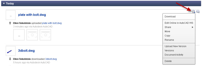
In the Documents list, click the icon on the right (see the arrow pointing to it) and choose Download.
Do you use Autodesk 360?
Do you save drawings in the cloud? Do you use your own company’s service or do you use Autodesk 360? Do you have a need to access drawings in the field? Via mobile devices? Leave a comment!
This is a guest post by AutoCAD guru Lee Ambrosius. Lee Ambrosius is a Principal Learning Content Developer at Autodesk, Inc. He worked on the user documentation for over six releases, but now primarily works on the developer documentation. Lee has authored a number of AutoCAD related books under the For Dummies brand and has been a technical editor and contributing author on the AutoCAD and AutoCAD LT Bible books since the AutoCAD 2005 and AutoCAD LT 2005 Bible edition. He has also been an instructor of Customization/Programming sessions at Autodesk University for over 8 years. Find Lee posting articles on his blog at hyperpics.blogs.com or tweeting AutoCAD related information at twitter.com/leeambrosius.
AutoCAD 2014 is the latest release of the AutoCAD program and builds on all of the functionality that was introduced with AutoCAD 2013 and its shipped updates. This latest release introduces improvements to some of the most commonly used drawing and annotating tools, while enhancing the performance of raster images, adding new functionality to geographic locations, among much more.
Interacting with the AutoCAD Environment
You are constantly interacting with the AutoCAD environment when you are opening or saving drawing files, starting commands, or simply looking for help.
Command Line
One of the most unique features of the AutoCAD program is the Command Line. Unlike most Windows-based programs, you do not need to use the ribbon, toolbars, pull-down menus or other user interface elements to start a command. If you have not discovered command aliases in AutoCAD yet, you have been missing out on one of the most productive features available. If you have been using command aliases, the Command Line improvements will by far make you even more productive.
All AutoCAD professionals have to deal with standards. But when a drawing is worked on by multiple people and revised over months or even years, standards can deteriorate quickly. AutoCAD’s CAD Standards tools let you check drawings against your standards. You can check the following in a drawing:
Layers
Text styles
Dimension styles
Linetypes
Create a standards file
A standards file is like a regular drawing but it has a filename extension of .dws. To create a standards file, you just create a drawing that has the standards you want — — layers, text styles, dimension styles, and linetypes. You can use an existing drawing for your standards file, but be sure to purge all layers, linetypes, dimension styles, and text styles that you don’t want.
When your drawing is the way you want it, here’s what you do:
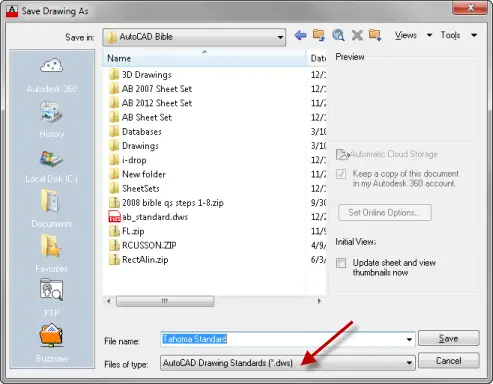
Choose Application Button, Save As.
From the Files of Type drop-down, choose AutoCAD Drawing Standards (.dws).
In the File Name text box, type a name for the standards file.
In the Save In drop-down list, choose a location for the file that is in the Support File Search Path.
Click Save to save the drawing standards file.
Test standards
To use your standards file, you associate it with your current drawing — or a template. If you have a template that you use regularly and you associate the template with a standards file, every drawing that you start based on the template is associated with that standards file. Cool!
Then you test your drawing. You can test drawings against a standards file one by one (interactively) or as a group (batch auditing). In this post, I cover testing an individual drawing.
To associate a standards file with an open drawing, follow these steps:
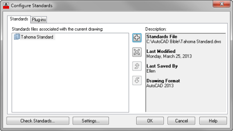
Choose Manage tab, CAD Standards panel, Configure. This is the STANDARDS command. The Configure Standards dialog box opens.
Click the + button, navigate to your standards file, and click Open. (By the way, you can associate more than one standards file with a drawing.)
Click the Plug-ins tab and uncheck any standards you don’t want to check. All four standards types are checked by default. (The choices you make persist for future standards checks.)
Click OK to close the Configure Standards dialog box and return to your drawing.
You can immediately check a drawing against the standards file by clicking the Check Standards button in the Configure Standards dialog box, but if you aren’t there, choose Manage tab, CAD Standards panel, Check to start the CHECKSTANDARDS command and open the Check Standards dialog box
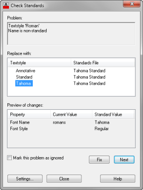
The Check Standards dialog box lists items in the drawing that don’t match the standards file, one by one. Here’s how to use this dialog box:
Look at the first problem in the Problem section of the dialog box.
In the Replace With section, choose a replacement for the nonstandard item. All eligible replacements according to the standards file are listed here.
Look at the Preview of Changes section to see how the replacement will affect your drawing.
To make the replacement and standardize your drawing, click the Fix button. To ignore the problem and go on to the next one, click the Next button.
AutoCAD displays the next problem, so continue to Fix or Ignore each problem.
When you’re done, the Check Complete message box provides a short report. Click Close to close the message.
Click Close to return to your drawing.
When you fix problems — for example, you change the name of Layer1 to Object — AutoCAD purges unused objects from the drawing. In this example, AutoCAD would purge Layer1.
Specifying standards settings
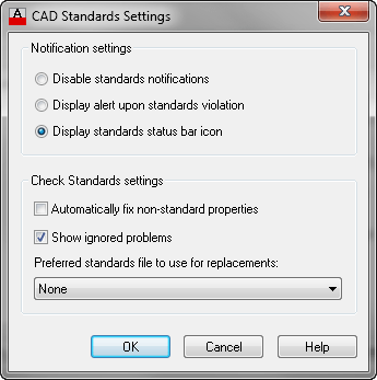
You can specify how the CAD standards feature works. Choose Manage tab, CAD Standards panel, Configure and click the Settings button to open the CAD Standards Settings dialog box.
In the Notification Settings section, choose one of the following:
Disable standards notifications. You won’t get any real-time notification of standards problems, but you can still check standards by using the Check Standards dialog box at any time.
Display alert upon standards violation. You’ll see a message if your drawing is associated with a standards file and you make a change that is not in accord with the standards file.
Display standards status bar icon. You’ll see a small icon with an exclamation point on the AutoCAD status bar if there is a nonstandard object in the drawing. A balloon appears, notifying you that a standards violation has occurred. Click the link or icon to open the Check Standards dialog box where you can fix the problems.
In the Check Standards Settings section, you can check Automatically Fix Non-standard Properties to automatically fix non-compliant drawings. Automatic fixing applies only when a drawing object has a name that matches a standard but has different properties. For example, if a standards named object that should be blue and the current drawing has a line on the object layer that is black, AutoCAD will change the line to blue.
Check Show Ignored Problems to display any problems that were not fixed in the standards check report.
From the Preferred Standards File to Use for Replacements drop-down list, choose a standards file to use by default in the Replace With section of the Check Standards dialog box. This standards file is used only if you choose to automatically fix nonstandard properties and the associated standards file does not provide a suitable replacement.
Do you use the Standards feature in AutoCAD? Please share any tips by leaving a comment!
Start the MTEXT command. (On the ribbon, choose Home tab, Annotation panel, Multiline Text.)
At the Specify first corner: and Specify opposite corner:prompts, click to place the text in your title block — or anywhere you want. The Text Editor tab appears on the ribbon and you see the text editor in your drawing.
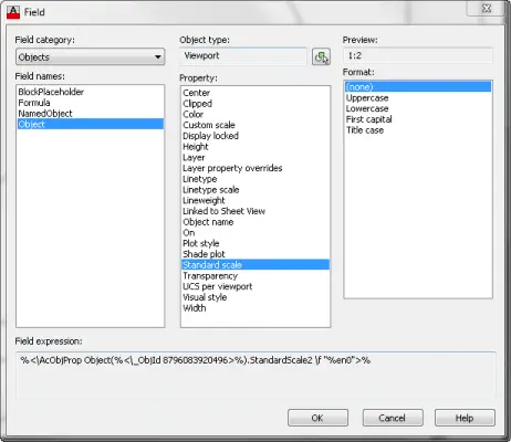
Inside the text editor, right-click and choose Insert Field to open the Field dialog box.
From the Field Category drop-down list, choose Objects.
Under Field Names, choose Object.
To the right of the Object Type box, click the Select Object button.
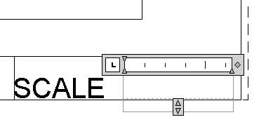
Back in your drawing, select the layout for which you set the scale. You can only select one object. The dialog box returns and the Object Type box reads Viewport.
In the Property box, choose Standard Scale if you chose a standard scale in the Properties palette when setting the scale. If you specified a custom scale, choose Custom Scale. You’ll see a preview of the text in the Preview box at the upper-right corner of the dialog box. For a scale, you usually don’t need to specify a format, since there isn’t any text, just numbers. You can see how the dialog box looks on the right
Click OK to close the Field dialog box.
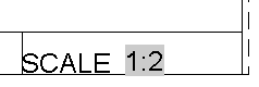
Click outside of the Text Editor to place the text of the layout’s scale. Your Mtext now shows the scale of the viewport as you see at the right.
What’s so cool about this method is that the field updates when you change the scale of the viewport. If you save the drawing, plot, do a regen, or open the drawing, the field will update automatically. You can update the field manually with these steps:
Double-click the text to activate the Text Editor.
Ralph, a subscriber to my AutoCAD Tips Newsletter, sent me a drawing that he called “an embarrassment.” He wouldn’t explain the details of why he thought it was so bad, but wanted some advice about how to fix drawings that have been revised over many years.
Old system variables
Some of the issues could be related to old system variables. For example, in this drawing, DIMASSOC is set to 1, which creates non-associative dimensions. That means that when the dimensions objects are edited, the dimensions don’t update automatically. AutoCAD has offered associative dimensions since Release 2002, but if the drawing was created before then, you’ll see non-associative dimensions.
You’ve certainly heard the principle that you should use layers to give objects properties. When you create a layer, you give that layer a
Color
Linetype
Lineweight
Transparancy
Plotstyle
Also, for 3D drawings, you can apply a material to a layer with the MATERIALATTACH layer.
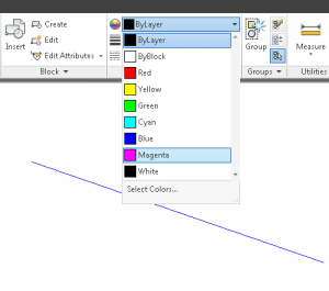
But it is all too easy to make an exception for an object and change it so that a property is not according to its layer. For example, you can select an object, and choose any color for it by going to the Home tab, Properties panel, Object Color drop-down list.
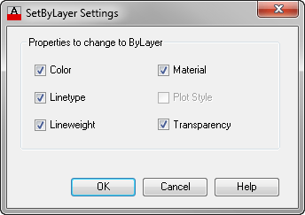
When you decide that this is a mistake (made by someone else, of course), you can easily return objects to the properties assigned by their layer with the SETBYLAYER command.
Here are the prompts:
Command: SETBYLAYER Current active settings: Color Linetype Lineweight Transparency Material Select objects or [Settings]: 1 found Select objects or [Settings]: Change ByBlock to ByLayer? [Yes/No] <Yes>: Y Include blocks? [Yes/No] <Yes>: 1 object modified.
I must admit that this command has more prompts than I would like. You might want to create a custom command that automates the block-related prompts for you.
If you choose the Settings option, you get this dialog box.
Note: The Plot Style option is available only if you are using named plot styles.
In this dialog box, you can specify which of the properties you want to include when you set an object’s properties to its layer properties.
Do you use this command? Do you have a way of streamlining it? Leave a comment to share with others!
You should always start a new drawing either from an existing drawing (Application Button, Save As) or from a template.
What is a template?
A template is just like a drawing, but when you start a drawing from a template, the template creates a clone of itself, remaining unchanged. Many people have multiple templates that they use. For example, it’s common to have a template for each sheet size.
Templates commonly include a title block on a layout tab with all the labeled boxes required by an organization’s drawings.
Any setting that is saved in a drawing can be saved in a template. Some settings are saved in the Windows registry and can’t be saved in a template; these settings persist from drawing to drawing.
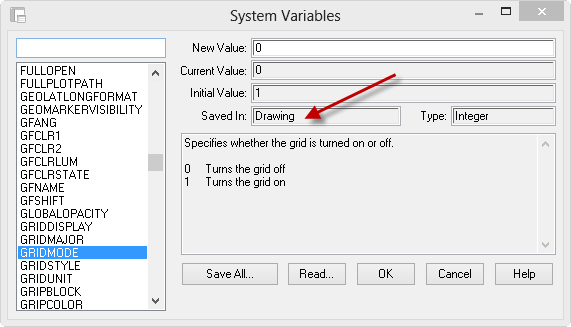
How do you know where a setting is saved? AutoCAD’s Help used to contain this information, but no longer. Now, you can go to an Express Tool called System Variable Editor. You can get there by going to Express Tools tab, Tools panel, System Variable Editor. You can also type SYSVDLG. (Thanks to this point on another AutoCAD Tips blog for this useful information.)
The System Variables dialog box opens. On the left, click any item, type the 1st letter of the system variable you’re interested in, and then scroll to find the exact system variable you want. Then look in the Saved In text box to find where the system variable is saved.
But this list of system variables may not tell you everything. For example, I couldn’t find one for the UNITS command settings. Help also used to provide a list of system variables related to commands, but no longer.
How to create a custom template
If you have a drawing with settings that you want to save, use that. Erase any drawing objects that you want. Don’t forget to check the Layout tabs for unwanted objects, such as viewports.
It’s a good idea to check the most common settings to make sure they are what you want. Here are some ideas:
The UNITS command sets the measurement type and precision.
The DSETTINGS command controls snap and grid, polar tracking, object snap, 3D object snap, dynamic input, quick properties (the small palette), and selection cycling.
The LAYER command which creates layers and defines their properties. You want your templates to already contain all of the layers that you will need when you draw.
The LTSCALE command, which sets the linetype scale factor.
The DIMSTYLE command, which creates dimensions. Your templates should contain all of the dimension styles that you will need when you draw.
The STYLE command, which creates text styles. Likewise, you want your text styles to be ready for you in your drawings.
The LAYOUT command which sets paper space viewports and scales
The PAGESETUP command which specifies settings for plotting and publishing
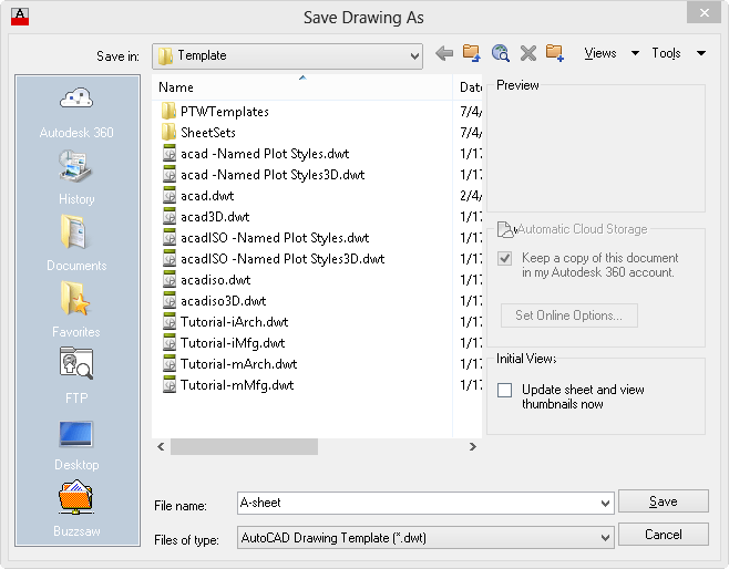
When you’re done, save your drawing and choose Application button, hover over the Save As item. and choose AutoCAD Drawing Template. AutoCAD opens the Save Drawing As dialog box, with the folder automatically set to your Template folder and the file type set to AutoCAD Drawing Template (*.dwt).
In the File Name text box, type a name for your template and click Save.
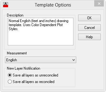
The Template Options dialog box opens. Type a description and click OK.
How to edit a template
To edit a template, just open it like you open a regular drawing, make the changes and save it again. But sometimes, it’s hard to find those templates, lost in the labyrinth of Window’s folders.
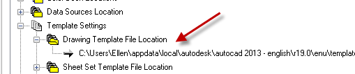
To find where your templates are stored, start the OPTIONS command and click the Files tab. Expand the Template Settings item, then expand the Drawing Template File Location item, as you see here.
How to use a template
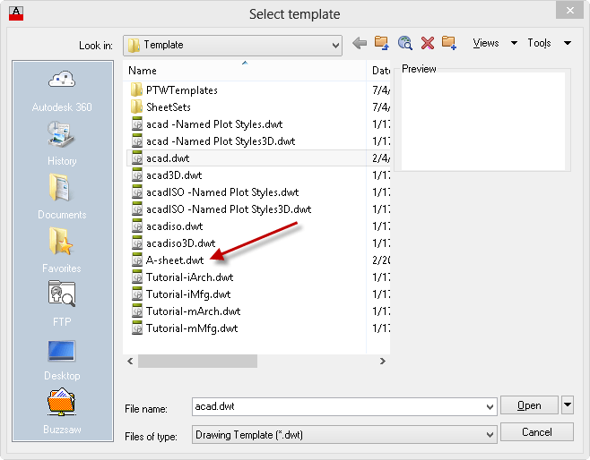
To use a template, choose Application button, New. In the Select Template dialog box, choose the template you want and click Open or just double-click the template.
What are your favorite template settings? Leave a comment!
Recently, a reader of my book, AutoCAD 2013 Bible, was reading something I wrote about the ribbon. He undocked it. (You can do that by right-clicking at the very end, in the blank gray space and choosing Undock.) Then, he clicked the X on the ribbon, which closed it. (Of course, I never recommended doing that.) Uh-oh! He finally guessed that he could type ribbon on the command line, but he was angry at me for not explaining how to get it back.
So I thought I would provide some information about how to fix problems that occur when you inadvertently mess up how AutoCAD’s user interface looks.
Fix the ribbon
Type ribbon on the command line to display the ribbon. The RIBBONCLOSE command closes the ribbon.
If the ribbon gets undocked, drag it upwards until it snaps into place.
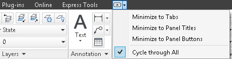
You can collapse the ribbon so that it doesn’t take up as much space. Click the down arrow at the right end of the ribbon tab names and choose one of the options: Minimize to Tabs, Minimize to Panel Titles, or Minimize to Panel Buttons. Try them out and see which option works best for you.
Fix the command line
Similarly, you can type commandline to display the command line window. You can type commandlinehide to hide it.
Display and hide the menu bar
By default, the menu bar is not displayed. But you can use the MENUBAR system variable to show or hide it. Set this system variable’s value to 0 to hide it and to 1 to display it.
What else affects the user interface?
There are many more commands and system variables that affect the user interface. To find them all, press F1 in AutoCAD to open the Help window. In the Search box, type Commands for Working With the Application Window.
We all make mistakes, so we all need to undo tasks in AutoCAD. Here’s a list of ways to undo actions. Please leave a comment to add to this list.
The UNDO command
Everyone knows about the UNDO and U commands. Let’s start with the U command. It undoes your last command (if possible–you can’t undo certain actions such as saving and printing). You can also find it on the Quick Access toolbar. Finally, you can do what most people do — press Ctrl+Z.
Important: While we don't collect cookies, some of our 3rd-party services (such as PayPal and WordPress) do, to give you a safer and better browsing experience. Read about how we use cookies and keep your personal information secure by reading our Privacy Policy here.