This tutorial requires AutoCAD 2010 or later and shows how to create a mesh solid jar.
- Start a new drawing using acad3d.dwt.
- Switch to the 3D Modeling workspace by choosing it from the Workspace Switching pop-up menu on the right side of the status bar or next to the Quick Access toolbar at the upper-left corner of your screen.
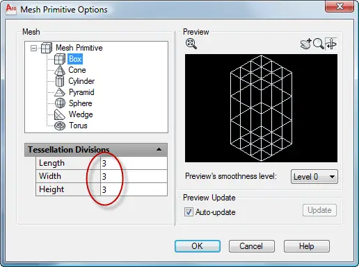
- Check that the tessellation divisions are the default 3 in each direction by clicking the Mesh Modeling tab, and then the dialog box launcher arrow at the right end of the Primitives panel title bar. Click OK.
- Still on the Mesh Modeling tab, in the Primitives panel, click Mesh Box. Follow the prompts:
Specify first corner or [Center]: Click anywhere on the XY plane.
Specify other corner or [Cube/Length]: c (for the Cube option)
Specify length: 2
- My mesh cube was rotated so I use the ROTATE command, selected the cube, specified a corner for the base point, and then used the Reference option. At the Specify the reference angle <0>: prompt, I picked one corner, and at the Specify second point: prompt, I picked the next corner. At the Specify the new angle or [Points] <0>: prompt, I pressed Enter to align the cube with the X axis.
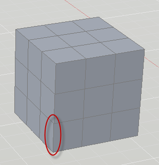
- In the Subobject panel, choose Edge from the Object Filter drop-down. Then choose Move Gizmo just to the right.
- Hold down the Ctrl key and click the bottom edge of any corner, circles in the above image. The Move Gizmo appears.
- Move your cursor until the XY plane (yellow) highlights, then push inward (into the cube). At the Specify stretch point or [Base point/Undo/eXit]: prompt, type .25.
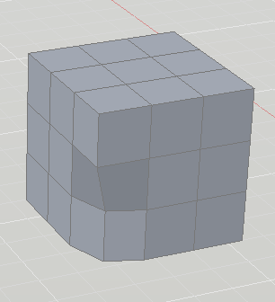
- Repeat for the other corners, being careful to deselect the previous edge first by pressing Esc. I hold Shift and my mouse’s wheel to transparently orbit, but you can use any method to change the viewpoint and access the other corners.
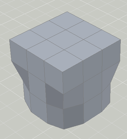
- In the Subobject panel, switch to the Face filter and the Scale Gizmo.
- Select the top center face. The Scale Gizmo appears. Select the XY plane (it becomes yellow — this isn’t always easy, but keep trying). At the Specify scale factor or [Base point/Undo/Reference/eXit]: prompt, enter 2.
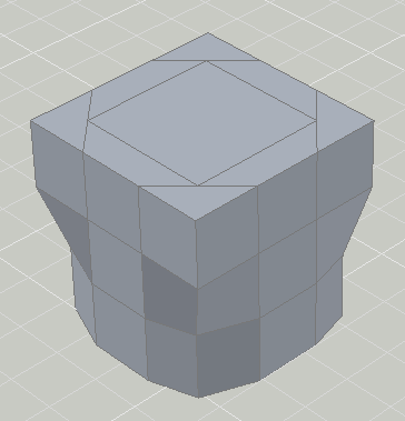
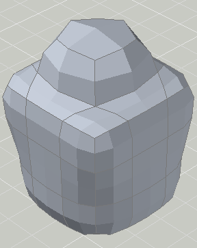
- On the Mesh Modeling tab, Mesh panel, click Smooth More. Select the mesh solid, and end selection.
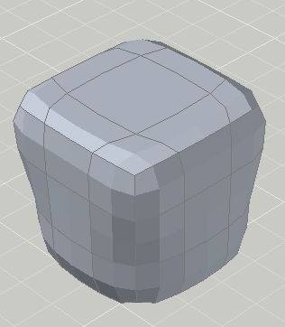
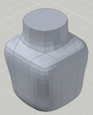
- To create the neck of the jar, choose Extrude Face from the Mesh Edit panel. Ctrl-select the top middle face and drag it upward. At the Specify height of extrusion or [Direction/Path/Taper angle] <2.0000>: prompt, enter .75.

- To flatten the top, choose Add Crease from the Mesh panel. Ctrl-select the top, middle face and end selection. At the Specify crease value [Always] <Always>: prompt, press Enter.
- On inspection, it seems like it could use more smoothing, so choose Smooth More again and select the model.
I wanted to shell out the inside, but every time I tried, AutoCAD stalled or told me “No solution for an edge.” You can try it at your own risk:
- On the Convert Mesh panel, choose Convert to Solid.
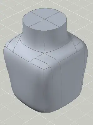
- On the Home tab, Solid Editing panel, click the bottom drop-down list and choose Shell. Select the solid and end selection.
- At the Remove faces or [Undo/Add/ALL]: prompt, select the top faces. I find this difficult to impossible.
- At the Enter the shell offset distance: prompt, enter .1.
I also tried making a copy, scaling it down, putting the smaller version inside the larger one, and using the SUBTRACT command. I wasn’t successful with that either. I’m open to suggestions. Leave a comment!
- Combine or subtract 2D shapes to create custom shapes - February 17, 2022
- Working with linetype scales - January 18, 2022
- Rename named objects–blocks, dimension styles, layers, and more - December 21, 2021

 Instagram
 LinkedIn
 Facebook

Don’t know how old this post is but I’ll give my 2 cents.
After converting the mesh to a 3d solid use the Clean command (Solid Editing Panel, choose Clean in dropdown menu where Shell is also located). This rids the Crease surface of it’s multiple faces. Then shell as you attempted previously. Also, the shell thickness is of concern as too thin will give the “NO lumps left in body” error. My guess is this has to do with the level of smoothness.
felicidades por el tutorial, es de gran ayuda. Gracias.
Make the jar as given in the tuotrial.
Set UCS as View.
Choose 3D wireframe for visual style
Draw a line from the top (Intersection of the mesh lines) of the jar to the bottom (2.75)
Now go Copy command.
Select the jar as the object and enter
Select the center of the line as the base point.
Paste the object at the center of the drawn vertical line.
Now select scale.
Select one the jars as the object
Select center of the same drawn vertical line as the base point
Set .9 as the scale factor and enter.
The smaller jar is set right in the center of the bigger jar.
Go to Subtract
Select the bigger jar. Enter
Select the smaller jar. Enter.
You get a shelled out jar.
try it with sectioning.
Thank you so much Ellen. I am a retired old engineer who did not have the priviledge of acad in my time but try to self teach to keep my mind busy. Solid mesh freaked me out especially in ribbons mode. This tutorial allowed me to get the jist of it and wow!its amazing stuff. Thank you.
thank you verymuch