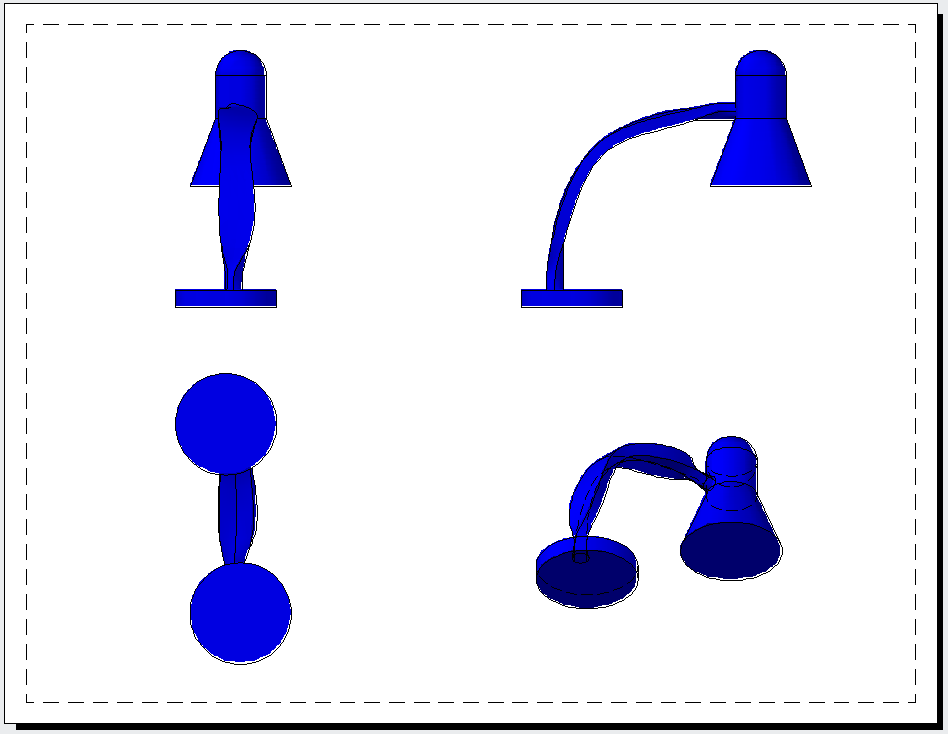
Starting with AutoCAD 2012, you can use the VIEWBASE command to quickly create 2D views of your 3D model. These views are called view objects. The command prompts you to create views based on the default 3D views, such as Top, Front, SE Isometric, etc. You can choose a shading style, as well. It’s quick and easy.

Here are the steps:
- After creating your 3D model, click a layout tab. You must be in paper space on a layout. I recommend using the 3D Modeling workspace.
- If a viewport appears, click it and press the DEL key on your keyboard to delete it.
- Start the VIEWBASE command. The DRawing View Creation tab displays on the ribbon, where you can choose and change settings.
- At the prompt to specify the location of the base view, click on the layout to place the view object.
- To place the next view, on the Drawing View Creation tab, go to Orientation panel> View drop-down list and choose a view. You can also change the scale on the tab’s Appearance panel, using the Scale drop-down list. Finally, you can change the shading style on the View Style drop-down list. You can choose from Wireframe, Wireframe with Hidden Edges, Shaded, and Shaded with Hidden Edges.
- Press Enter to get a prompt to specify the location of the second view and click where you want it to appear.
- Continue to specify settings and place additional views, as you see in the model above.
- Press Enter to end the command when you’re done.
To edit a view object, select it and choose Edit View on the Drawing View Creation tab; this is the VIEWEDIT command.
Use the VIEWPROJ command to add additional views. When you see the prompt to select the parent view, select the base view and then pick the location of the new views.
As you edit your model, you can update the view objects. You’ll see a notification that your model has changed and you can click the link there to update the view objects. This is the VIEWUPDATE command.
The VIEWSTD command sets defaults for future view objects, but doesn’t apply to existing ones.
Here’s a brief video showing the placement of two views.
- Combine or subtract 2D shapes to create custom shapes - February 17, 2022
- Working with linetype scales - January 18, 2022
- Rename named objects–blocks, dimension styles, layers, and more - December 21, 2021

 Instagram
 LinkedIn
 Facebook
[…] Use AutoCAD's VIEWBASE command to create 2D views of your 3D … You can follow any responses to this entry through the RSS 2.0 feed. Both comments and pings are currently closed. « Virgo attraction […]
[…] 2012 introduced the VIEWBASE command to create 2D view objects. (I have a tip on this command here.) 2D view objects lets you show 2D views of your 3D models in a […]
I haven’t downloaded and used R2013 yet, but I have a doubt:
What happens if the model space contains more than 2 3D models?
[…] See my earlier AutoCAD tip on the VIEEWBASE command–before it was updated in AutoCAD 2013. […]
I’m using Civil 3D as AutoCAD 2013. I was looking forward to trying this as soon as I heard about it but my program seems to not contain this feature. I can find viewbase in my help file. but it’s not in my cui. It appears as a option as I start to type the command, but when I select it, it says “command not found”. Could there be a problem with my installation, or does Civil 3D just not support this?
I have the same problem. I’m using Civil 3D and i get the message “command not found” !
In the readme file for Civil 3D 2013 it states the command is not available – http://docs.autodesk.com/CIV3D/2013/ENU/readme_civil.html
I’ve tried adding missing AcModelDoc.arx, ModelDoc.cuix, ModelDoc.mnr files with no luck. I took files from AutoCAD 2013 Trial installation and put them into same folders of Civil 3D 2013 installation. Menus appered in Ribbon but none of commands are working.
Please post a workaround if you know it…
I am using AutoCAD MEP 2012, This command “viewbase” is not availabe
We create mechanical plant type drawings.
A typical general arrangement drawing is as such:
Models are XREF’d into model space. Layer colours are assigned for the drawing (eg main plant full thickness, adjacent plant half thickness).
Viewports created in PAPER SPACE. Where sections are required, we use 3DCLIP. Viewport SHADE PLOT is set to LEGACY HIDDEN.
This method has some serious limitations, but Autodesk do not seem to offer a better workflow. Extremely frustrating.
VIEWBASE completely ignores layers, so it cannot be used to produced drawings described above.
Can anybody shed some light PLEASE.
George,
I can’t visualize what you’re doing, but there are several ways to convert 3D drawings to 2D ones. Here are some of them:
https://allaboutcad.com/tutorial-convert-a-3d-solid-to-a-3-view-2d-drawing-in-model-space/
https://allaboutcad.com/convert-a-3d-solid-to-a-2d-drawing-with-a-hidden-view/
https://allaboutcad.com/converting-3d-drawings-into-2d-drawings/
Maybe one of these will help.
Hi Ellen, thanks a lot for your reply.
Our line of work is in metal smelting plants, hence our plant models are very large and complex. We collaborate with lots of other parties, hence we use XREFs as a way of keeping a ‘live’ and up to date model, which shows a hierarchy, or relationship between the various ‘systems’.
As such, we want our 2D drawings to be ‘live’, which is why we stay away from FLATSHOT, SOLPROF, etc.
The type of drawing I described in my previous is what we call a GA (general arrangement). For example, it may be a drawing of a conveyor that we supply, shown alongside other equipment that is supplied by others, not us. Hence, we want our conveyor to be shown in full lineweight, and the adjacent stuff in half, or a lighter lineweight. THIS IS AN INTEGRAL PART OF MANY OF OUR DRAWINGS.
Plans and elevations are relatively straightforward, but once you get to sections or require hidden line detail, I find that AutoCAD has some serious shortfalls. Which is disappointing, because AutoCAD allows you to develop full mechanical and structural relationships through XREF hierarchy. It also has excellent modelling functionality and layer tools. But then it stops short of allowing you to create a good drawing out of it all.
As an AutoCAD user of many years, I have long suffered in silence, thinking ‘the next version’ will fix the shortfalls of the previous. In our industry, AutoCAD is standard, so I’m pretty much confined to it.
George,
I cannot agree with you more. Autodesk provide these fantastic tools, but stop just short of making them useful. This particular command has been stolen directly from Inventor. However, when creating the section, as you mentioned, it ignores layer information, critical to creating a clear drawing.
I don’t get Autodesk. They add these 3D features into AutoCAD, cloud rendering, lofting, etc, but never develop the ability to create final deliverable drawings. That’s what we get paid for, the 3D render is a bonus; a nice bonus, but is not our bread and butter.
You do not suffer alone…
Ryan
Hi Ellen,
I am using AutoCAD 2013 SP2 and making viewbase views from Inventor 2013 parts and assemblies. Occasionally our views become “unresolved” and will not update. Is their anyway to repath the views to the models?
Thanks
Daly
How to do quick dimension for 3d generated view in layout in autocad 2014.
This is a fine command if your file has only one part or you want to generate various views of an overall assembly. It is not helpful if you need to create drawings of individual parts in a an assembly.
I don’t see how it’s much better than using SOLVPROF and SOLDRAW. In fact, it’s not as versatile because you can’t edit the resulting 2d linework in model space because it isn’t there…I don’t know where it is.
How may I convert my isometric drawing 3rd angle projection using view base command and how may I put dimension isometric view after inserting to lay out
THANK YOU FOR HOW TO.
I have been using the view base command to create a first angled drawing of my model, however when I try and plot the drawing in the 2D views it does not appear in the print. So I am just left with dimensions and the 3D model which I put in the top right. Can anybody help me plot the 2D views and make them print?
Does it work in autocad 2010 ?
I’m using AutoCAD 2017 and just starting to try the 3D to 2d detail drawing.
Our business just requires clear unambiguous drawings in First Angle projection. Is there a command to switch from 3rd angle to 1st angle projection when transferring to paperspace?
Definitely, 3d modeling represents a world of options for those who convert the design
in our passion, in my case I have a repository of useful free download models, visit my place
available for study or business
Does it work in 3dmax? great model!!