Are you getting the look you need for your dimensions? Are you constantly making little adjustments? If dimensions aren’t your friend, you need to get more comfortable with dimension styles.
In this tutorial, you create an architectural dimension style. Why? Because the default style is a mechanical look and by changing it to architectural, you’ll get a chance to work with many of the dimension style features.
Note: The values that I chose in this tutorial are my choices. They don’t come from any standard; you should follow the standards in your office or discipline.
Follow these steps:
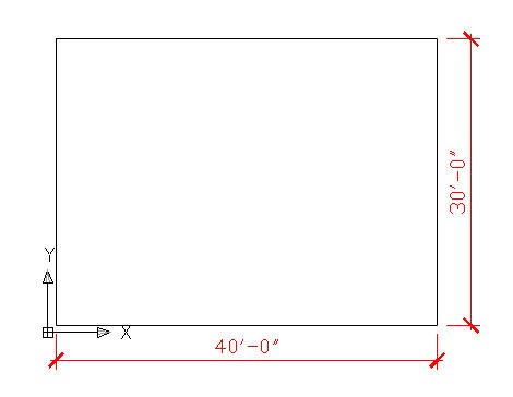
Open any architectural drawing. If you don’t have one, open a new drawing and choose Format > Units. Change the units to architectural. Draw a rectangle 40′ wide by 30′ high and zoom to its extents. Zoom out a little more so you have room for your dimensions.
If you’re starting with a new drawing, create a new layer, named dim and make it a different color from your rectangle. Set it current. Make sure that OSNAP is on with a running object snap for endpoints.
Choose Dimension > Dimension Style or click Dimension Style on the Dimension toolbar to open the Dimension Style Manager.
Click New. In the Create New Dimension Style dialog box, enter arch_96 and click Continue. The 96 refers to the scale that we’ll use later.
Note: We won’t use it now, but click the Use For drop-down list. You can see that you can create a style that applies only to a certain type of dimension. For example, you may want angular dimensions to have open arrows but the rest of your dimensions to use architectural ticks. So you could create a dimension style just for angular dimensions.
Click Continue.
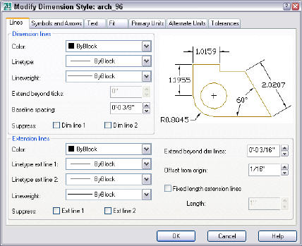
The New Dimension Style: arch_96 dialog box opens. Click the Lines tab.

Note: In the Dimension Lines section, you can make the dimension line’s color, linetype, and ineweight different from the rest of the dimension. We’ll leave it the same, which is more typical.
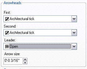
Note that the Extend Beyond Ticks box is grayed out. That’s because you don’t have architectural ticks (and I hope you don’t have any other kind either). To create the ticks, click the Symbols and Arrows tab. In the Arrowheads section, choose Architectural tick from the First drop-down list. The Second drop-down list follows suit automatically. Choose Open from the Leader drop-down list. The arrow size should be 3/16″.

Click the Lines tab again. Set the Extend Beyond Ticks value to 1/16″.
Leave the Baseline Spacing value at 3/8″. This is the spacing between the dimension lines of two baseline dimensions.
Note: You can suppress the first or second dimension line. These are the lines to the left or right of the text. As you’ll see later, architectural dimensions only have one dimension line, so this doesn’t apply to us.
In the Extension Lines section, you can change the color, linetype, and lineweight of the extension lines. We’ll leave them unchanged.
Note: You can also suppress the first or second extension line. Normally, you would do this only for a special situation where an extension line doesn’t fit well. You would create an override to a dimension style for this purpose. (That’s for another tip!)
Change the Extend Beyond Dim Lines value to 1/8″. This is the amount that the extension lines extend beyond the dimension lines.
Change the Offset from Origin value to 1/8″. This is the distance from the object you’re dimensions to the extension line.
Click the Symbols and Arrows tab, just to see what’s there. (Before Release 2006, you’ll have one tab called Lines and Arrows.) You’ve already change the arrowhead. The rest of this tab is for center marks, arcs, and radial dimensions, which don’t concern us, so click the Text tab.

The first step is to choose a text style. If you don’t already have one, you can create it now. Click the Ellipsis button to the right of the Text Style drop-down list.
In the Text Style dialog box, click New. Name the style dimtext_96 and click OK.
In the Text Style dialog box, choose a font from the Font Name drop-down list. Architects like a font that looks hand-drawn. I chose Stylus BT. If you don’t have that on your system, choose another one. The important point is to keep the Height at 0′-0″ because that allows the height in the dimension style to take precedence. Click Apply and click Close.
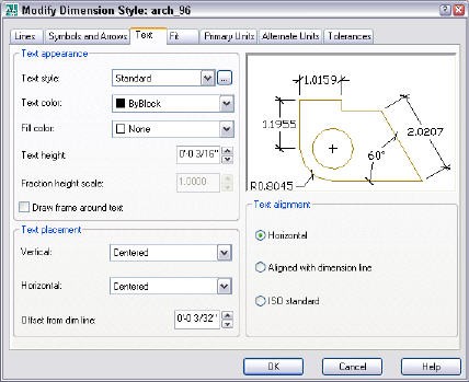
Back in the New Dimension Style: arch_96 dialog box, choose dimtext_96 from the Text Style drop-down list. You can change the color of the text and also place a fill box around the text (for legibility over other objects), but we’ll leave these the same. The text height should be 3/16″. Note that the Fraction Height Scale text box is grayed out. We’ll come back to that later.
In the Text Placement section, choose Above from the Vertical drop-down list.
In the Text Alignment section, choose Aligned with Dimension Line. Notice how the preview changes dramatically and starts to look like an architectural dimension.
Click the Fit tab. This tab specifies how lines and arrows fit, especially if there isn’t enough room. You also set the scale here.
In the Text Placement section, choose Over Dimension Line, with Leader.
In the Fine Tuning section, check the Draw Dim Line Between Ext Lines so that even if the text can’t fit between the extension lines, there’s still a dimension line.
In the Scale for Dimensions section, change the scale to 96. Of course, this value depends on the size of your model and the size of the paper you’ll be using. You would use the Scale Dimension to Layout option for dimensioning in paper space on a layout. See my tip Dimension in paper space.
Click the Primary Units tab. From the Unit Format drop-down list, choose Architectural. Leave the precision as 1/16″.
From the Fraction Format drop-down list, choose Diagonal.
In the Zero Suppression section, uncheck the 0 Inches check box to show 0 inches.
Now click the Text tab and change the Fraction Height Scale value to .75. (You can’t do this until you’ve specified a unit format that uses fractions.
If you want to include alternate units, such as metric (if you’re main units are Imperial), use the Alternate Units tab.
Click OK.
In the Dimension Style Manager, with arch_96 selected, click Set Current and click Close. You’re now ready to dimension.
Choose Dimension > Linear or click Linear on the Dimension toolbar. Press Enter so you can select an object. Pick any side of the rectangle (or any object in your pre-existing drawing, if you opened one). Specify a location for the dimension line, leaving room for the text.
 Happy dimensioning!
- Combine or subtract 2D shapes to create custom shapes - February 17, 2022
- Working with linetype scales - January 18, 2022
- Rename named objects–blocks, dimension styles, layers, and more - December 21, 2021

 Instagram
 LinkedIn
 Facebook
am so grateful for your tips. am in uganda and your book and website has helped me a lot to learn auto cad. i was having a problem with dimension styles but now its goin to be ok . thnks to yur tip
how can i convert the decimal form of dimension into the form (e.g: 36’8,59’3 etc) in autocad 2004
Is the apostrophe in place of a decimal? You can use a comma or a space, but I don’t see any way to use an apostrophe. To use a comma, for example, in the Dimension Style dialog box, on the Primary Units tab, click the Decimal Separator drop-down list. I don’t have 2004, so I’m looking at 2012, but I don’t remember any changes in this. You’ll have to look for it. Perhaps someone else has an idea of how to use an apostrophe.
Great tutorial! Is there a way to have 2 dimension alternates to go with your primary units? For example: metric (primary), decimal inches (alternate #1), feet and inches (alternate #2).
Not that I know of. There’s just a setting for 1 alternate measurement.
For some reason my dimensions are not showing the fractional portion of a dimension. Example: if I have a line that is 12′-0 1/2″, it displays as 12′-0″. How can I correct this?
FYI: I’m using Autocad 2006.
I’ve never seen this, but I would check the dimension style, especially if you created one. There’s a setting, I think on the Primary Units tab, that suppresses zeroes–maybe it has something to do with that. Does it suppress a decimal amount if you show in decimals?
I have another method that I use to create an architectural dimension style that is more flexible than the one shown in the tutorial. Using the following method you can create one style that can be used at any scale. Follow the tutorial above, but with a few small changes. First of all, leave out any mention of the “scale” in the dimension and text style names. The next step is where the magic happens. When you are on the “Fit” tab, in the “Scale for Dimension features” section, change the radio button from “Use overall scale of:” to “Scale dimensions to layout”. This setting will create a dimension style that will scale automatically based on the viewport scale. You don’t need multiple dimension styles at different scales. If the viewport scale changes after the dimensions are created, just use the “Update” dimensions command and the dimensions will change to the correct scale.
Thank’s for your lecture
ellen ilove it
missing show list 24 language “Italian.bin, Japanese.bin, Polish.bin, Slovak.bin, Turkish.bin..ưhen open autocad 2004 ???
help me
Ellen,
The zero suppression has no effect on weather the fraction will display or not. Also, by changing to “Decimals” the decimal numbers will display. Just so you understand, I’m fairly new to Autocad. Is there something about how the drawing was set up originally that could be causing this?
How do I make a comma (,) to separate on dimension text
example:
1,000
Ellen, How do I “paste” dimension lines back together? I receive drawings from clients and any dimensions in their drawings explode and become individual lines and text making it very hard to adjust or even delete. Even when adding my own dimension style and using it in their drawing the same thing happens. Is there some setting or command that causes this? Thanks so much for your help!
I’m not aware of a setting that automatically explodes dimensions. See what the DIMASSOC value is. It should be 2. If it isn’t, try DIMREASSOCIATE. But that just associates dimensions with their objects; it doesn’t turn an exploded dimension into a whole one.
Ellen,
It seems without warning, the dimensions went from being above the dimension line to centered in the line. No matter how I format or how many times I format the dimension style, the dimension is displayed centered in the dimension line instaed of above it. Any clues?
Ellen,
It seems without warning, the dimensions went from being above the dimension line to centered in the line. No matter how I format or how many times I format the dimension style, the dimension is displayed centered in the dimension line instead of above it. Any clues?
Does that happen in a new drawing?
Ellen,
Thank you for a great tutorial. Is there a way of having a separator between the three zeros and a number for a drawing set in millimeters and which the dimension is 1000 millimeters or more (like layout dimensions of building gridlines. EXAMPLE: Dim is 10000 mm for 10 meters). In Middle East – no matter how big is the project, layout dimensions are always in millimeters. Or shall I just use Text Override in the Properties Manager/Changer.
Ellen,
I recently upgraded to ACA 2012, and although I’ve worked with AutoCAD for ten years I’ve never encountered the need (until now – new client) to isolate the color for the (Arrowheads) Ticks.
I’m aware of (but not experienced in) the commands: DIMCLRD, DIMCLRE and DIMCLRT; but not really sure if those will help me in isolating the tick mark color.
I’m trying to print the dimensions in a color (which I know how to do via the Layer Property Mgr and Plot Styles); however, changing the dim lines and extention lines also changes the tick mark to the same oolor. In most CAD drawing cases, that makes sense, but I’m finding myself wishing the Dim Style Manager included the same variables for color as it does for Dim Lines and Extensions.
I assume there is some way to do this… any thoughts or directions would be helpful.
Thanks
Hello Ellen, I looking for the setting dimstyle with two dimension and use it in the same time. I saw a drawing can use dimstyle in-cm and in the same line of the object with dimstyle can add the dimension in mts-ft. how he can do that. he doesn’t need to change the units in the drawing or convert.
Thanks in advance for any help.
Felipe
Felipe
Use DDim open the “alternate style tab” and tick the “show alternate units” and set the “Multiplier for alt units” to 0.3937007 for inch to mm or 2.54 for mm to inch
Hans Graveman
anybody knows how to create a “leader” into two different colors??if knows please write to me at sa.alam02@yahoo.com
I will be highly grateful to you.
Alam, Do you mean to create a leader that has a different color arrow than the leader line? If so, you can create a leader with one color, a leader line of a second color and text of a third color. You will need to create an arrow as a block and then, in multi-leader definition dialog, select your arrow as a User-Defined arrow.
hi ellen i want to know how to make dimensions in mm bigger like the architecture dimensions.
any way thanks for this one it has really helped me.
Hi Ellen,
I’d like to ask, if I can attach a certain LAYER to my DIM-STYLE choice?
For instance, if I choose DIM-STYLE-DETAIL, I’d like to have the LAYER-DETAIL right the moment I click on the DIM-STYLE.
For LINES, ARCS etc. I did a MACRO in my CUI. But how does it work with DIM-STYLE?
Thank you very much
I have a button on my toolbar with this macro:^C^C(if(not c:dml)(load “dml”)) dml
The dml refers to a lisp routine written by Leonid Nemirovsky,
see below.
;;;Dimension Linear
;;;Puts dimensions and text on proper AutoCAD layers
;;;Leonid Nemirovsky October 11, 2004
;;;modified for Duffy Engineering
;;;by Jerry Middelstadt December 23, 2004
;;;modified for Cold Spring Granite Layers
;;;by Jerry Middelstadt Monday, May 19, 2008
;;;
;;;dml.lsp
;;;
(defun c:dml(/ ql)
(setq ql (getvar”clayer”))
(command”layer” “m” “Dim” “c” “12” “” “”)
(command”dimlinear” pause pause pause)
(setvar”clayer” ql)
(princ)
)
You can change the layer & color by modifying the: (command”layer” “m” “your layer” “c” “your color or bylayer” “” “”)
Manfred and Jerry you can use use the new [Dimlayer] setting to make the dimensions go to a preset layer
Hi,
how i will give dimensions in autocad instead of 6′-8″ —-> i want 6-8
please help.
thanks for the help!
hello,Im getting problem in dimensions,right now Im getting my dimensions like boxes, square and rectangle boxes ieIm not getting my dimensions and text properly on the position. what to do? please hepl me out.i have autocad 2012.
Nice post