
 If you use leaders, you should consider creating a style. Once you save the style, you can use it whenever you need a leader.
Here are the steps to create a multileader style:
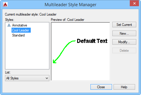
- Go to Home tab, Annotation panel and click the down arrow to expand the panel. Click the Multileader Style icon to open the Multileader Style Manager dialog box.
- Click the New button to open the small Create New Multileader Style dialog box. Type a new style name and choose an existing style to start with. You can choose to make the style annotative by clicking the Annotative checkbox. Click Continue. The Modify Multileader Style dialog box opens, showing the name of the style that you specified. This dialog box has 3 tabs.
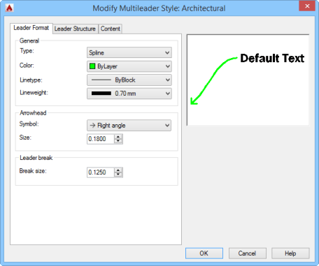
- On the Leader Format tab, specify the leader type (Straight, Spline, or None).

- Choose a color. The default is ByBlock — the leader takes on the color of the current layer — or the current color.
- Choose a linetype. If you don’t see the linetype you want, choose Other from the Linetype drop-down list to open the Select Linetype dialog box.
- Choose a lineweight from the Lineweight drop-down list.
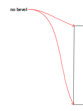
- In the Arrowhead section, choose a symbol (arrowhead type) and size. The one you see above is called Right Angle.
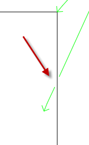
- The Break Size is the gap that is created when you use the DIMBREAK command — it sets the gap when the leader crosses another object. You can see an example on the right.
- Click the Leader Structure tab to specify points, angles, landing settings, and scale.
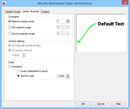
- Choose the maximum number of leaders points. In the example, I’m using a spline leader type, so you don’t really see points, but usually a leader has 2 points, its arrow end and a bend point, which connects to the landing line (next to the text). You can add more if you want, but you can’t have fewer than 2 points.
- You can set the first and second segment angles if you want to make sure that all leaders use the same angle. You can choose from 15, 30, 45, 60, and 90.
- You can set the second segment angle, too. This one is horizontal by default.
- In the Landing Settings section, you can choose to automatically include a landing (a short, horizontal segment that leads to the text) or not. The default is to include a landing. You can also set the landing distance, which is its length.
- Like a block, you can make a multileader annotative. (See my tip on annotative objects here.) In the Scale section you can check the Annotative checkbox and you can also specify a scale or automatically scale the multileader to the scale of a layout.
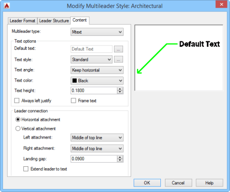
- On the Content tab, you specify options relating to text and the connection between the leader and the text. The Text Options section lets you set default text, a text style, the text angle, the text color, and the text height.
- In the Leader Connection section of the Content tab, you can choose a horizontal attachment (the default) or a vertical attachment. The vertical attachment is important when you may have more than one line of text. Do you want the landing line to go to the top line of text, the bottom line of text, or to the middle? Choose from the drop-down lists for left and right attachment.
- Finally, you can specify the gap between the landing line and the text or extend the leader to the text (no gap).

 How do you style your leaders? Leave a comment below!

Ellen Finkelstein is the author of the best-selling AutoCAD & AutoCAD LT Bible, which started with R14. Ellen has written extensively on AutoCAD, including articles for Autodesk’s website and features for AutoCAD’s Help system. Ellen’s first book was AutoCAD For Dummies Quick Reference.
Latest posts by Ellen Finkelstein (see all)
- Combine or subtract 2D shapes to create custom shapes - February 17, 2022
- Working with linetype scales - January 18, 2022
- Rename named objects–blocks, dimension styles, layers, and more - December 21, 2021


My company has a block for a balloon that has attributes for a bm item #, qty, and id. I created an annotative multileader style with block options>user block>our balloon.
I can move my balloon around using the grip and the leader comes along for the ride. No drawing separate leaders that need to be redrawn if you move your balloon…
Beware of the pesky leader landing distance that wants to set itself to a default 0.36, I set the landing distance to 0.0, then uncheck the automatically include landing box.
Thanks for all your tips over the years! I’m wondering, for an annotative multileader style, should I choose a text style that is annotative as well? Or does the leader style take care of the text size…does it matter which text style or can I choose either an annotative or non-annotative text style?
Thanks for all your tips
Hi Sir,
Good Morning, I would like to have you post a Beam Dynamic Block.
How to create a Steel Beam Dynamic Block with Lookup link to excel files,
with input dimension Length, Width, Flg Thickness, Web Thickness and Radius Corners as well.
Can you kindly shown the step in creating this block, so that I can speed up my work.
Appreciate if you can post this block to show the step or video.
Thank You
I’m wondering, is there a way to make an alias that will change to the dimension layer, change dimension style, and invoke the linear dimension command all at once? For example:
dd1 switches to the dimension layer, sets the dimension style to 1″ – 1′, and invokes the lineal dimension command.
dd2 switches to the dimension layer, sets the dimension style to 1/2″ – 1′, and invokes the lineal dimension command.
dd3 switches to the dimension layer, sets the dimension style to 3/4″ – 1′, and invokes the lineal dimension command.
I’d like to do this for leaders as well. If that’s not possible, is it possible to make a new toolbar that would have an icon for each?
I know I can set up a tool pallet for this, but I don’t keep tool pallets showing on my desktop, and I can’t seem to find a way to only show the pallet I want rather than all of them. That extra click to select the correct pallet is what I’m trying to eliminate. I prefer a toolbar or an alias, but if I have to go with a pallette i want one to show by itself and that way I can just hover, and select the one I want. Thanks in advance for your help.
Nice Ellen… I became more clear about multileader style..thanks a lot.
Does anybody have any insight to share on my question about making an alias to change dim layer, style, and invoke linear dimension?
I face a problem with multileader, which is facing left side. the lading distance is made 0 then also the land is still present. can anybody give solution?…..
How I can create my own style leaders?
I would like to add custom shapes to the pull down in mleader, not a block, add to the default.
haha….. im never know this. we can use arc style to make multy leader 😀 …GREAT ..THANKSSSS
How I can create my own style leaders?
how do you change the font in a multileader bubble. The edit Attribute or properties does not give me an option to change the font.
Hi David,
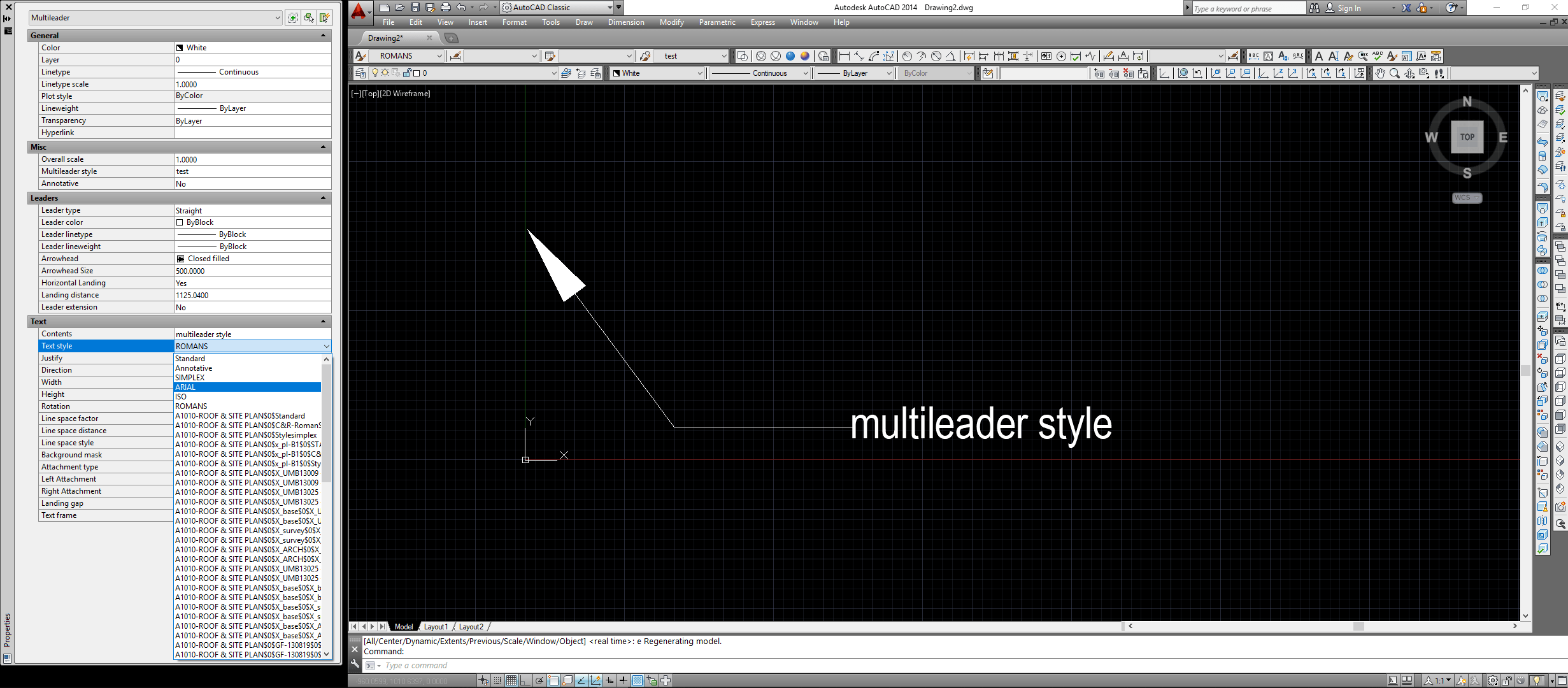

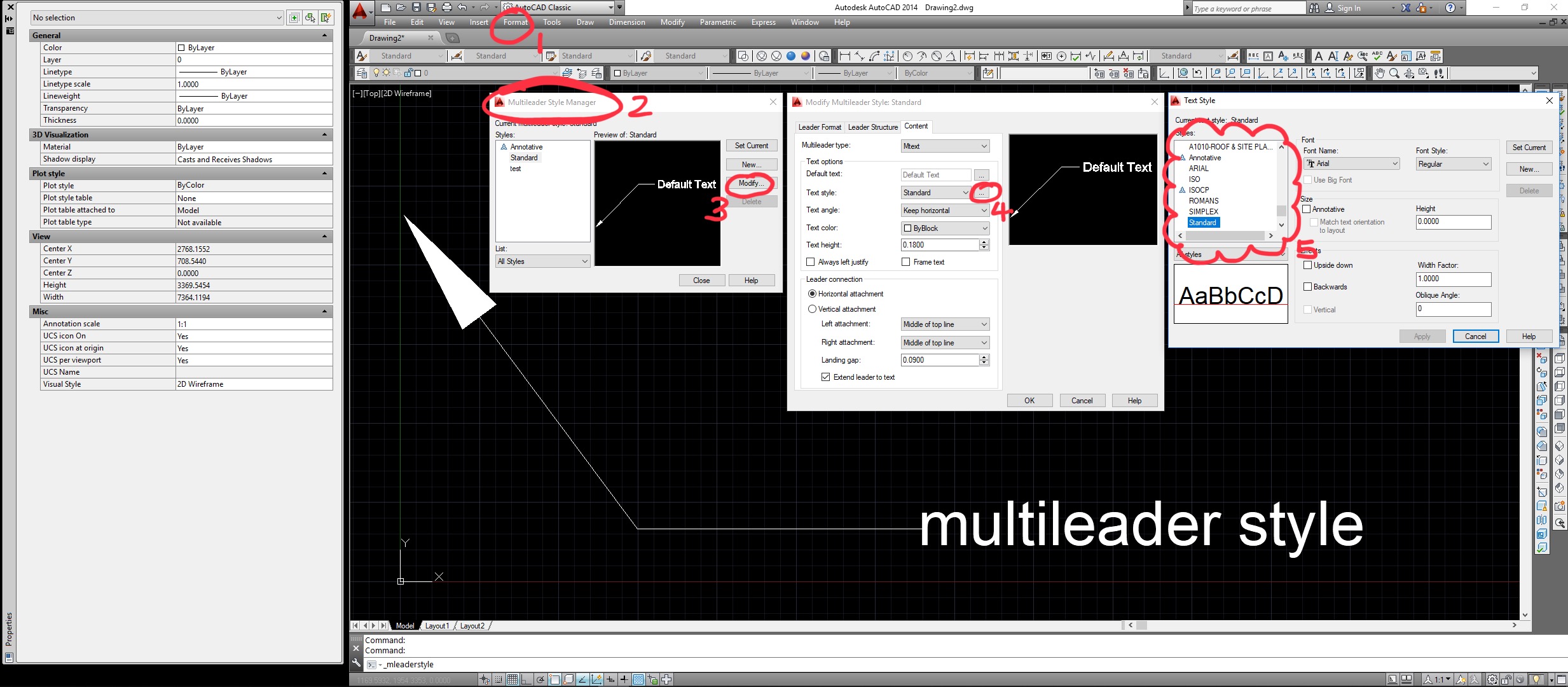

There are a couple of steps you can change font in a multi-leader style:
1. Click on the multi-leader text, go to Modify/Properties. This will bring up the Properties window where you can change the font under Text (see below):
2. To modify the Multileader Style globally within the file, follow steps as depicted in screenshot below: